EP0992772B1 - Mounting and control system for optical imaging systems - Google Patents
Mounting and control system for optical imaging systems Download PDFInfo
- Publication number
- EP0992772B1 EP0992772B1 EP99402476A EP99402476A EP0992772B1 EP 0992772 B1 EP0992772 B1 EP 0992772B1 EP 99402476 A EP99402476 A EP 99402476A EP 99402476 A EP99402476 A EP 99402476A EP 0992772 B1 EP0992772 B1 EP 0992772B1
- Authority
- EP
- European Patent Office
- Prior art keywords
- optical imaging
- bearing
- imaging device
- support member
- mounting
- Prior art date
- Legal status (The legal status is an assumption and is not a legal conclusion. Google has not performed a legal analysis and makes no representation as to the accuracy of the status listed.)
- Expired - Lifetime
Links
Images



Classifications
-
- B—PERFORMING OPERATIONS; TRANSPORTING
- B60—VEHICLES IN GENERAL
- B60R—VEHICLES, VEHICLE FITTINGS, OR VEHICLE PARTS, NOT OTHERWISE PROVIDED FOR
- B60R11/00—Arrangements for holding or mounting articles, not otherwise provided for
- B60R11/04—Mounting of cameras operative during drive; Arrangement of controls thereof relative to the vehicle
-
- H—ELECTRICITY
- H04—ELECTRIC COMMUNICATION TECHNIQUE
- H04N—PICTORIAL COMMUNICATION, e.g. TELEVISION
- H04N23/00—Cameras or camera modules comprising electronic image sensors; Control thereof
- H04N23/20—Cameras or camera modules comprising electronic image sensors; Control thereof for generating image signals from infrared radiation only
-
- G—PHYSICS
- G01—MEASURING; TESTING
- G01J—MEASUREMENT OF INTENSITY, VELOCITY, SPECTRAL CONTENT, POLARISATION, PHASE OR PULSE CHARACTERISTICS OF INFRARED, VISIBLE OR ULTRAVIOLET LIGHT; COLORIMETRY; RADIATION PYROMETRY
- G01J5/00—Radiation pyrometry, e.g. infrared or optical thermometry
- G01J5/02—Constructional details
- G01J5/04—Casings
-
- G—PHYSICS
- G01—MEASURING; TESTING
- G01J—MEASUREMENT OF INTENSITY, VELOCITY, SPECTRAL CONTENT, POLARISATION, PHASE OR PULSE CHARACTERISTICS OF INFRARED, VISIBLE OR ULTRAVIOLET LIGHT; COLORIMETRY; RADIATION PYROMETRY
- G01J5/00—Radiation pyrometry, e.g. infrared or optical thermometry
- G01J5/02—Constructional details
- G01J5/04—Casings
- G01J5/047—Mobile mounting; Scanning arrangements
-
- G—PHYSICS
- G01—MEASURING; TESTING
- G01J—MEASUREMENT OF INTENSITY, VELOCITY, SPECTRAL CONTENT, POLARISATION, PHASE OR PULSE CHARACTERISTICS OF INFRARED, VISIBLE OR ULTRAVIOLET LIGHT; COLORIMETRY; RADIATION PYROMETRY
- G01J5/00—Radiation pyrometry, e.g. infrared or optical thermometry
- G01J2005/0077—Imaging
Definitions
- the present invention relates generally to viewing systems, and more particularly to a mount and control for a driver viewer enhancement system.
- DVE driver viewer enhancement
- the application of such DVE systems in combat vehicles has caused problems that are derived from the fact that the DVE system is typically configured in a periscope fashion.
- the openings in the vehicle armor are typically rectangular in shape and approximately 6.4cm (2.5 inches) wide by 15.2 to 25.4 cm (6 to 10 inches) long.
- the DVE systems normally replace periscope day sights in these openings.
- the DVE systems typically include a head protruding out of the armor through a mounting block adaptor.
- the head consists of a window, a folding mirror, and three or more lenses.
- the optics are placed vertically in a cylinder neck within the mounting block, thereby permitting azimuth movement of the periscope.
- a seal is required in the neck.
- the uncooled detector array and electronics are in a housing under the mounting block inside the vehicle.
- periscope based systems are more costly due to the need for extra optical elements, i.e., a folding mirror, an actuation mechanism, and a window. It is advantageous to reduce the cost of such a system.
- a unique new configuration is needed that utilizes a forward looking (telescopic) sensor instead of a system using periscope architecture.
- a second problem with periscope based systems is the large amount of space they require and the limited number of mounting positions that are possible with such a configuration. It is desirable that the sensor module be as small as possible to allow maximum flexibility in mounting the unit in armored vehicles. In some vehicles the protruding housing underneath the mounting block adaptor of a periscope based system obstructs hatch movement and driver egress.
- the patent US 3 888 563 describes an arrangement for supporting an observation and measuring stand in the top of a vehicle so as to be swingable like a pendulum in all directions.
- the patent US 3 509 792 discloses a ball mount for mounting guns in armored vehicles : it is adapted to receive a sight block.
- the patent US 5 729 016 describes a night vision system for use with non-military vehicles.
- the system includes a night vision camera mounted on top of the vehicle, and a mechanism for adjusting the pointing angle of the night vision camera.
- the pointing mechanism includes a joystick that sends electronic signals to a motor drive assembly that moves the night vision camera.
- This document does not disclose mechanical interconnection between a controllable optical imaging sensor module located external of the vehicle and an operator control located internal of the vehicle
- An object of the present invention is to provide a cost effective driver viewer enhancement system. This object is achieved through the use of a mounting and control system that provides for a forward looking (telescopic) sensor instead of a system using periscope architecture.
- An additional object of the present invention is to provide a compact mounting and control system for a driver viewer enhancement system that provides for maximum flexibility in mounting the unit within a vehicle.
- This object is achieved through the advantageous use of a mounting block adaptor for the sensor module that is simple and cost effective in construction to permit quick and easy installation and removal in a vehicle opening, simple environmental sealing, independent elevational and rotational (or azimuth) movement, simple one hand operation, and low mounting block control adaptor cost.
- a mounting and control system as set out in claim 1.
- Preferred x features are set out in claims 2 to 8.
- the invention provides for mechanical interconnection between a controllable optical imaging sensor module located external of a vehicle and an operator control located internal of the vehicle that includes an orthogonal journal arrangement for facilitating internal operator control of the sensor module.
- the sensor module is supported by a tube that is interconnected to a sleeve bearing by a ball and socket joint that provides for the limited pivotal adjustment of the module about a horizontal axis.
- the sleeve bearing is supported by a mounting block, which provides for rotational adjustment of the sensor module about a vertical axis.
- the sleeve bearing has a generally cylindrical outer surface, and an inner hollow region having rectangular and trapezoidal cross-sectional configurations that extend within two vertical perpendicular planes.
- the tube is free to pivot within the sleeve bearing in the plane including the trapezoidal cross-section only, thereby providing for elevational adjustment of the sensor module.
- the tube is restricted to rotation within the plane including the trapezoidal cross-section by a pin fixed to the sleeve bearing for slidably engaging a ball portion of the ball and socket joint.
- Figures 1 through 10 depict a mounting and control system for an optical imaging system.
- an optical imaging device includes an infrared light path to the sensor array 17 controlled by shutter 13 in the sensor module or optical imaging device 11.
- the sensor module is not discussed in detail herein so as not to unnecessarily complicate the present description, but are more completely described in copending US application Serial No. 09/248,507, filed February 10, 1999 , published as US 2001/0 045 516 A1 or EP 0 992 773 A .
- the sensor module 11 includes an optical imaging device having an array of infrared radiation detector cells 17 and an optical system consisting exclusively of refractive optical components, including an objective lens 45 (see Figure 2 ), for projecting the infrared radiation emanating from a scene onto the array of infrared sensitive cells, and a housing containing the array of cells and the optical system and part of the system electronics.
- the array information is converted to a digital form at 19 and transmitted from the optical imaging or sensor module 11 to the image processing, display and control module 25 by way of harness 15.
- Harness 15 includes a modulation-free bidirectional digital communication path and passes through a hollow member depicted in Figures 2-10 .
- the image processing and display module 25 is spaced from the optical imaging device for displaying an image of the scene.
- the sensor module 11 is preferably limited to an overall size of approximately 2.5 inch square by 6.0 inch long. Reference to the aforementioned copending application may be had for further details of the electrical components illustrated in Figure 1 .
- the sensor module 11 is supported near the upper end of a hollow tube or support member 31 which extends downwardly through a mounting block or mounting member 27, 29 terminating at a control handle 33.
- the tube 31 is preferably cylindrical in shape, although alternative shapes can be used, which will be readily apparent to those skilled in the art.
- the control handle 33 extends orthogonally from the tube 31.
- the mounting block 27, 29 includes two half portions that are rigidly fixed together and the mounting block 27, 29 is typically fixed to a vehicle by flanges 67 and 69.
- the interior of the tube 31 houses an image information conveying cable 63 which interconnects the sensor module 11 with the display and control module 25 by way of a further cable (not shown) which connects to the electrical connector 37.
- the handle 33 provides for control of the positioning of the sensor module 11 by an operator.
- the tube 31 is positioned within a hollow sleeve bearing 35. As will be discussed in more detail below, the tube 31 is prevented from rotating with respect to the sleeve bearing 35 about a vertical axis 30 due to interference between a pin 55 that extends from the sleeve bearing 35 and into a slot 57 on a portion of the tube 31.
- the sleeve bearing 35 is configured to rotate within the mounting block 27, 29 about the vertical axis 30.
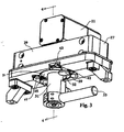
- the sleeve bearing 35 and, therefore, the sensor module 11 are configured to rotate within the mounting block 27, 29 about vertical axis 30 through slightly more than thirty degrees to either side of a straight forward position (depicted, for example, in Figure 3 ).
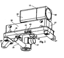
- the sleeve bearing 35 and sensor module 11 are configured to rotate about vertical axis 30 ninety degrees from the straight forward position depicted in Figure 3 to a stowage position depicted in Figure 2 . Therefore, in total, the sleeve bearing 35 is free to rotate within the mounting block 27, 29 through a preferred range of about one hundred and twenty degrees about the vertical axis 30, although alternative ranges can extend the freedom of rotation to a full 360 degrees or beyond if desired.
- the range of rotational movement of the sleeve bearing 35 within the mounting block 27, 29 is defined by control stop devices.
- At least one end stop pin 41 extends from an outer surface of the sleeve bearing 35 and is received within at least one end stop recess 42 in the mounting block 27, 29.
- the end stop recess 42 restricts the rotation of the sleeve bearing 35 and the sensor module 11 by interfering with and limiting the movement of the end stop pin 41, thereby providing azimuth control stop devices.
- a portion of the end stop recess 42 includes a releasable latch-type member or leaf spring 43, which is positioned in the end stop recess 42 such that when the sensor module 11 is in the stowage position the pin 41 is engaged with member 43.
- the member 43 prevents or deters the pin end stop 41 from moving out of the stowage position, thereby preventing or deterring the sensor module 11 from rotating about vertical axis 30 out of the stowage position.
- the sensor module 11 In the stowage position, the sensor module 11 is folded within the mounting block 27, 29, which will protect the sensor module 11 during installation in the vehicle, dismounting from the vehicle, or when the sensor module 11 is not in use.
- An added advantage of the stowage position is that when the sensor module 11 is in this position the objective lens 45 is protected within the protective cowling provided in most vehicles. Note that when the sensor module 11 is in the stowage position the handle 33 is oriented towards the operator, which allows the operator to easily grasp and manipulate the sensor module 10 using the handle 33.
- the latch-type member 43 has a release lever or button 39 that, when depressed, allows the end stop pin 41 to move out of the stowage position without interference or with minimal interference from member 43.
- the button 39 is positioned such that the operator can grasp the handle 33 with one hand and simultaneously actuate the button 39 with the same hand, for example by using the back side of the hand.
- the sleeve bearing 35 further includes a bearing notch 51
- the mounting block 27, 29 further includes a spring loaded roller 49, which interact to provide a detent neutral or forward position, as depicted in Figures 3 and 5 .
- the spring loaded roller 49 mates with the notch 51 when the sensor module 11 and sleeve bearing 35 are oriented in the straight forward position, thereby providing slight deterrence from rotation at this position.
- the operator can overcome this deterrence by using the handle 33 to rotate the sleeve bearing 35 and the sensor module 11, thereby forcing the spring loaded roller 49 out from notch 51.
- a potentiometer roller mechanism 47 ( Figures 5 , 7 and 9 ) is provided on the mounting block 27, 29 that has a rubberlike peripheral surface and is spring loaded against sleeve bearing 35 to give an azimuth directional reading of the sensor module 11.
- the directional readout may be displayed in a graphical mode on the display 23.
- the sleeve bearing 35 is formed in two halves and has a generally cylindrical outer surface and an inner hollow region 36 including a relieved region 32 that allows for the limited pivotal motion of the tube 31 about a horizontal axis 34 within the sleeve bearing 35.
- This relieved region 32 gives the opening in which the tube 31 resides a race track shaped cross-sectional configuration, as depicted in Figure 5 .
- the inner hollow region 36 is generally depicted in Figure 6 and has rectangular and trapezoidal cross-sectional configurations that extend within two vertical perpendicular planes that intersect along axis 30.
- the tube 31 is free to pivot within the sleeve bearing 35 in the plane including the trapezoidal cross-section only, thereby providing for elevational adjustment of the sensor module 11.
- a ball and socket joint joins the tube 31 and sleeve bearing 35.
- the ball and socket joint includes a spherical ball portion 56 that is press-fit onto the tube 31.
- the spherical ball portion 56 of the tube 31 is received within a recessed spherical socket portion 58 on the interior of the sleeve bearing 35.
- the ball portion 56 has a slot 57 (as discussed earlier) that engages a pin 55 in the socket portion 58 of the sleeve bearing 35, which prevents the sensor from having pitch rotation.
- the pin 55 is positioned to extend perpendicularly to axis 34 and in the same direction as the objective lens 45 of the imaging device 11 in order to insure restriction of motion of the imaging device 11 to two perpendicular planes, thereby providing for elevational adjustment (along the plane in which the trapezoidal cross-sectional configuration of the inner hollow region of sleeve bearing 35 extends, and about horizontal axis 34) and rotational adjustment along a horizontal plane about the vertical axis 30.
- the sensor module 11 rotates about axis 34 for elevational adjustment and is aided by a friction mechanism 53 (see Figures 4, 6 and 7 ) for maintaining a selected elevational position of the sensor module 11.
- a friction mechanism 53 see Figures 4, 6 and 7 ) for maintaining a selected elevational position of the sensor module 11. Compare Figure 4 where the sensor module 11 is directed substantially horizontally with Figure 6 where handle 33 has been pushed forward and the sensor module has been elevated to nearly its preferred maximum elevation of ten to fifteen degrees.
- the friction mechanism 53 will provide sufficient friction between the socket portion 58 and the ball portion 56 to maintain the orientation of the sensor module 11 depicted in Figure 6 , unless an operator overcomes the friction by moving the handle 33.
- a friction mechanism 65 (depicted in Figure 5 ), similar to friction mechanism 53) is implemented for maintaining a selected rotational position of the sensor module 11 about vertical axis 30 by providing friction between the sleeve bearing 35 and the mounting block 27, 29.
- a seal between the ball portion 56 of the tube 31 and the socket portion 58 of the sleeve bearing 35 is achieved with an O-ring 61.
- Another O-ring 59 sealingly engages both the sleeve bearing 35 and the cylindrical opening in the mounting block 27, 29.
- this mounting block control adaptor provides simple environmental sealing, easy one hand operation for independent azimuth and elevation controls, and a protective stowage position.
- the mounting block control adaptor can be used in various applications. It is particularly well suited to for use with a forward looking sensor module in the majority of combat vehicles.
- the adaptor enables the use of a driver viewer enhancement system in vehicles where there is minimum amount of free space for protrusion and volume inside the vehicle under the mounting block.
- the present invention also readily lends itself to adaptation as a motorized control system with the inclusion of motors for providing rotational and elevational controls and motors or other mechanisms for controlling the release button 39.
Landscapes
- Engineering & Computer Science (AREA)
- Multimedia (AREA)
- Signal Processing (AREA)
- Physics & Mathematics (AREA)
- General Physics & Mathematics (AREA)
- Spectroscopy & Molecular Physics (AREA)
- Mechanical Engineering (AREA)
- Studio Devices (AREA)
- Fittings On The Vehicle Exterior For Carrying Loads, And Devices For Holding Or Mounting Articles (AREA)
- Cameras In General (AREA)
- Stereoscopic And Panoramic Photography (AREA)
Abstract
Description
- The present invention relates generally to viewing systems, and more particularly to a mount and control for a driver viewer enhancement system.
- In recent years thermal imaging systems, based on uncooled detector arrays, have come to be an important aid in driving at night and under adverse weather and battlefield conditions. These systems are generally known as driver viewer enhancement (DVE) systems. The application of such DVE systems in combat vehicles has caused problems that are derived from the fact that the DVE system is typically configured in a periscope fashion. The openings in the vehicle armor are typically rectangular in shape and approximately 6.4cm (2.5 inches) wide by 15.2 to 25.4 cm (6 to 10 inches) long. The DVE systems normally replace periscope day sights in these openings. The DVE systems typically include a head protruding out of the armor through a mounting block adaptor. The head consists of a window, a folding mirror, and three or more lenses. An elevation control mechanism is required for the folding mirror to provide a wide field of regard. The optics (lenses) are placed vertically in a cylinder neck within the mounting block, thereby permitting azimuth movement of the periscope. A seal is required in the neck. The uncooled detector array and electronics are in a housing under the mounting block inside the vehicle.
- One problem with such periscope based systems is that they are more costly due to the need for extra optical elements, i.e., a folding mirror, an actuation mechanism, and a window. It is advantageous to reduce the cost of such a system. A unique new configuration is needed that utilizes a forward looking (telescopic) sensor instead of a system using periscope architecture.
- A second problem with periscope based systems is the large amount of space they require and the limited number of mounting positions that are possible with such a configuration. It is desirable that the sensor module be as small as possible to allow maximum flexibility in mounting the unit in armored vehicles. In some vehicles the protruding housing underneath the mounting block adaptor of a periscope based system obstructs hatch movement and driver egress.
- The patent
US 3 888 563 describes an arrangement for supporting an observation and measuring stand in the top of a vehicle so as to be swingable like a pendulum in all directions. - The patent
US 3 509 792 discloses a ball mount for mounting guns in armored vehicles : it is adapted to receive a sight block. - These documents do not disclose a detector with electronics.
- The patent
US 5 729 016 describes a night vision system for use with non-military vehicles. The system includes a night vision camera mounted on top of the vehicle, and a mechanism for adjusting the pointing angle of the night vision camera. The pointing mechanism includes a joystick that sends electronic signals to a motor drive assembly that moves the night vision camera. This document does not disclose mechanical interconnection between a controllable optical imaging sensor module located external of the vehicle and an operator control located internal of the vehicle - An object of the present invention is to provide a cost effective driver viewer enhancement system. This object is achieved through the use of a mounting and control system that provides for a forward looking (telescopic) sensor instead of a system using periscope architecture.
- An additional object of the present invention is to provide a compact mounting and control system for a driver viewer enhancement system that provides for maximum flexibility in mounting the unit within a vehicle. This object is achieved through the advantageous use of a mounting block adaptor for the sensor module that is simple and cost effective in construction to permit quick and easy installation and removal in a vehicle opening, simple environmental sealing, independent elevational and rotational (or azimuth) movement, simple one hand operation, and low mounting block control adaptor cost. According to the invention there is provided a mounting and control system as set out in claim 1. Preferred x features are set out in claims 2 to 8.
- In a particularly preferred embodiment, the invention provides for mechanical interconnection between a controllable optical imaging sensor module located external of a vehicle and an operator control located internal of the vehicle that includes an orthogonal journal arrangement for facilitating internal operator control of the sensor module. The sensor module is supported by a tube that is interconnected to a sleeve bearing by a ball and socket joint that provides for the limited pivotal adjustment of the module about a horizontal axis. The sleeve bearing is supported by a mounting block, which provides for rotational adjustment of the sensor module about a vertical axis. The sleeve bearing has a generally cylindrical outer surface, and an inner hollow region having rectangular and trapezoidal cross-sectional configurations that extend within two vertical perpendicular planes. The tube is free to pivot within the sleeve bearing in the plane including the trapezoidal cross-section only, thereby providing for elevational adjustment of the sensor module. The tube is restricted to rotation within the plane including the trapezoidal cross-section by a pin fixed to the sleeve bearing for slidably engaging a ball portion of the ball and socket joint.
- The mounting and control system for an optical imaging device according to the invention is explained in detail by means of the examples illustrated in basic diagrams in
Figures 1 to 10 . - A more complete appreciation of the invention and many of the attendant advantages thereof will be readily obtained as the same becomes better understood by reference to the following detailed description when considered in connection with the accompanying drawings, wherein :
-
Figure 1 is a schematic diagram of an optical imaging system; -
Figure 2 is an isometric view of the mounting and control system of the present invention in a stowage position; -
Figure 3 is an isometric view similar toFigure 2 , but depicting the imaging device in the straight forward position; -
Figure 4 is a partial cross-sectional view along the lines 4-4 ofFigure 3 ; -
Figure 5 is a cross-sectional view along the lines 5-5 ofFigure 4 ; -
Figure 6 is a partial cross-sectional view similar toFigure 4 , but depicting the imaging device aimed at an increased elevation; -
Figure 7 is an isometric view similar toFigure 3 , but with one housing portion removed to reveal the sleeve bearing; -
Figure 8 is an isometric view similar toFigure 7 , but with one portion of the sleeve bearing removed to reveal the elevation ball joint; -
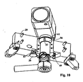
Figure 9 is an isometric view of the mounting and control system of the present invention from a different perspective and depicting the imaging device in one preferred extreme azimuth position; and -
Figure 10 is an isometric view similar toFigure 9 , but with one housing portion and one portion of the sleeve bearing removed to reveal the elevation ball joint. - Referring now to the drawings, where like reference numerals identify the same or corresponding parts throughout the several views,
Figures 1 through 10 depict a mounting and control system for an optical imaging system. - In
Figure 1 , an optical imaging device includes an infrared light path to thesensor array 17 controlled byshutter 13 in the sensor module oroptical imaging device 11. The sensor module is not discussed in detail herein so as not to unnecessarily complicate the present description, but are more completely described in copendingUS application Serial No. 09/248,507, filed February 10, 1999 US 2001/0 045 516 A1 orEP 0 992 773 Asensor module 11 includes an optical imaging device having an array of infraredradiation detector cells 17 and an optical system consisting exclusively of refractive optical components, including an objective lens 45 (seeFigure 2 ), for projecting the infrared radiation emanating from a scene onto the array of infrared sensitive cells, and a housing containing the array of cells and the optical system and part of the system electronics. The array information is converted to a digital form at 19 and transmitted from the optical imaging orsensor module 11 to the image processing, display andcontrol module 25 by way ofharness 15.Harness 15 includes a modulation-free bidirectional digital communication path and passes through a hollow member depicted inFigures 2-10 . The image processing anddisplay module 25 is spaced from the optical imaging device for displaying an image of the scene. After processing by the image processing circuitry 21, the information is displayed at 23. Thesensor module 11 is preferably limited to an overall size of approximately 2.5 inch square by 6.0 inch long. Reference to the aforementioned copending application may be had for further details of the electrical components illustrated inFigure 1 . - Referring generally to
Figures 2-10 , thesensor module 11 is supported near the upper end of a hollow tube orsupport member 31 which extends downwardly through a mounting block or mountingmember control handle 33. Thetube 31 is preferably cylindrical in shape, although alternative shapes can be used, which will be readily apparent to those skilled in the art. Thecontrol handle 33 extends orthogonally from thetube 31. Themounting block mounting block flanges tube 31 houses an imageinformation conveying cable 63 which interconnects thesensor module 11 with the display andcontrol module 25 by way of a further cable (not shown) which connects to theelectrical connector 37. Thehandle 33 provides for control of the positioning of thesensor module 11 by an operator. - The
tube 31 is positioned within ahollow sleeve bearing 35. As will be discussed in more detail below, thetube 31 is prevented from rotating with respect to thesleeve bearing 35 about avertical axis 30 due to interference between apin 55 that extends from thesleeve bearing 35 and into aslot 57 on a portion of thetube 31. However, thesleeve bearing 35 is configured to rotate within the mountingblock vertical axis 30. In the preferred embodiment, thesleeve bearing 35 and, therefore, thesensor module 11 are configured to rotate within the mountingblock vertical axis 30 through slightly more than thirty degrees to either side of a straight forward position (depicted, for example, inFigure 3 ). Additionally, thesleeve bearing 35 andsensor module 11 are configured to rotate aboutvertical axis 30 ninety degrees from the straight forward position depicted inFigure 3 to a stowage position depicted inFigure 2 . Therefore, in total, thesleeve bearing 35 is free to rotate within the mountingblock vertical axis 30, although alternative ranges can extend the freedom of rotation to a full 360 degrees or beyond if desired. - In the preferred embodiment, the range of rotational movement of the
sleeve bearing 35 within the mountingblock end stop pin 41 extends from an outer surface of thesleeve bearing 35 and is received within at least oneend stop recess 42 in the mountingblock end stop recess 42 restricts the rotation of thesleeve bearing 35 and thesensor module 11 by interfering with and limiting the movement of theend stop pin 41, thereby providing azimuth control stop devices. A portion of theend stop recess 42 includes a releasable latch-type member orleaf spring 43, which is positioned in theend stop recess 42 such that when thesensor module 11 is in the stowage position thepin 41 is engaged withmember 43. Once theend stop pin 41 travels into the stowage position, themember 43 prevents or deters the pin end stop 41 from moving out of the stowage position, thereby preventing or deterring thesensor module 11 from rotating aboutvertical axis 30 out of the stowage position. - In the stowage position, the
sensor module 11 is folded within the mountingblock sensor module 11 during installation in the vehicle, dismounting from the vehicle, or when thesensor module 11 is not in use. An added advantage of the stowage position is that when thesensor module 11 is in this position theobjective lens 45 is protected within the protective cowling provided in most vehicles. Note that when thesensor module 11 is in the stowage position thehandle 33 is oriented towards the operator, which allows the operator to easily grasp and manipulate the sensor module 10 using thehandle 33. - The latch-
type member 43 has a release lever orbutton 39 that, when depressed, allows theend stop pin 41 to move out of the stowage position without interference or with minimal interference frommember 43. Thebutton 39 is positioned such that the operator can grasp thehandle 33 with one hand and simultaneously actuate thebutton 39 with the same hand, for example by using the back side of the hand. Thesleeve bearing 35 further includes a bearingnotch 51, and the mountingblock roller 49, which interact to provide a detent neutral or forward position, as depicted inFigures 3 and5 . The spring loadedroller 49 mates with thenotch 51 when thesensor module 11 andsleeve bearing 35 are oriented in the straight forward position, thereby providing slight deterrence from rotation at this position. The operator can overcome this deterrence by using thehandle 33 to rotate thesleeve bearing 35 and thesensor module 11, thereby forcing the spring loadedroller 49 out fromnotch 51. - A potentiometer roller mechanism 47 (
Figures 5 ,7 and9 ) is provided on the mountingblock sensor module 11. The directional readout may be displayed in a graphical mode on thedisplay 23. - The
sleeve bearing 35 is formed in two halves and has a generally cylindrical outer surface and an innerhollow region 36 including arelieved region 32 that allows for the limited pivotal motion of thetube 31 about ahorizontal axis 34 within thesleeve bearing 35. Thisrelieved region 32 gives the opening in which thetube 31 resides a race track shaped cross-sectional configuration, as depicted inFigure 5 . The innerhollow region 36 is generally depicted inFigure 6 and has rectangular and trapezoidal cross-sectional configurations that extend within two vertical perpendicular planes that intersect alongaxis 30. Thetube 31 is free to pivot within thesleeve bearing 35 in the plane including the trapezoidal cross-section only, thereby providing for elevational adjustment of thesensor module 11. - A ball and socket joint joins the
tube 31 andsleeve bearing 35. Such a ball and socket joint is readily adapted to simple sealing techniques, as will be readily apparent to one skilled in the art. The ball and socket joint includes aspherical ball portion 56 that is press-fit onto thetube 31. Thespherical ball portion 56 of thetube 31 is received within a recessedspherical socket portion 58 on the interior of thesleeve bearing 35. Theball portion 56 has a slot 57 (as discussed earlier) that engages apin 55 in thesocket portion 58 of thesleeve bearing 35, which prevents the sensor from having pitch rotation. In the preferred embodiment thepin 55 is positioned to extend perpendicularly toaxis 34 and in the same direction as theobjective lens 45 of theimaging device 11 in order to insure restriction of motion of theimaging device 11 to two perpendicular planes, thereby providing for elevational adjustment (along the plane in which the trapezoidal cross-sectional configuration of the inner hollow region ofsleeve bearing 35 extends, and about horizontal axis 34) and rotational adjustment along a horizontal plane about thevertical axis 30. - The
sensor module 11 rotates aboutaxis 34 for elevational adjustment and is aided by a friction mechanism 53 (seeFigures 4, 6 and7 ) for maintaining a selected elevational position of thesensor module 11. CompareFigure 4 where thesensor module 11 is directed substantially horizontally withFigure 6 wherehandle 33 has been pushed forward and the sensor module has been elevated to nearly its preferred maximum elevation of ten to fifteen degrees. Thefriction mechanism 53 will provide sufficient friction between thesocket portion 58 and theball portion 56 to maintain the orientation of thesensor module 11 depicted inFigure 6 , unless an operator overcomes the friction by moving thehandle 33. A friction mechanism 65 (depicted inFigure 5 ), similar to friction mechanism 53) is implemented for maintaining a selected rotational position of thesensor module 11 aboutvertical axis 30 by providing friction between thesleeve bearing 35 and the mountingblock ball portion 56 of thetube 31 and thesocket portion 58 of thesleeve bearing 35 is achieved with an O-ring 61. Another O-ring 59 sealingly engages both thesleeve bearing 35 and the cylindrical opening in the mountingblock - In summary, the simplicity of this mounting block control adaptor provides simple environmental sealing, easy one hand operation for independent azimuth and elevation controls, and a protective stowage position. The mounting block control adaptor can be used in various applications. It is particularly well suited to for use with a forward looking sensor module in the majority of combat vehicles. The adaptor enables the use of a driver viewer enhancement system in vehicles where there is minimum amount of free space for protrusion and volume inside the vehicle under the mounting block. As will be readily apparent to one of skill in the art, the present invention also readily lends itself to adaptation as a motorized control system with the inclusion of motors for providing rotational and elevational controls and motors or other mechanisms for controlling the
release button 39. - Numerous variations of the present invention are possible in light of the above teachings. It is therefore to be understood that within the scope of the appended claims, the present invention can be practiced other than as specifically described herein.
Claims (8)
- A mounting and control system for mounting an optical imaging device (11) to a vehicle, comprising a support member (31) having the optical imaging device fixed at an end thereof, a bearing (35) supporting said support member for rotational movement about a horizontal axis, and a mounting member (27, 29) supporting said bearing for rotational movement about a vertical axis, characterized in that
the optical imaging device (11) includes an optical system and an electronic detector,
and in that it comprises
a ball and socket joint to join together said support member (31) and said bearing (35), to provide rotational movement about the horizontal axis, wherein said bearing has an inner hollow region configured to receive said support member;
a control handle (33) mechanically connected to said support member (31) at an opposite end opposite to the end having the optical imaging device (11) fixed thereto,
an image display module (25) for displaying images obtained by said optical imaging device, said image display module being remote to said optical imaging device,
wherein mounting member (27, 29) for supporting support member (31) is configured to mount said optical imaging device (11) to the vehicle such that said optical imaging system (11) is external to the vehicle and said control handle (33) and said image display module are internal to the vehicle, and wherein said support member defines a passageway comprising a communication path coupling said optical imaging device with said display module. - The system of claim 1 wherein:said bearing (35) has an outer surface that is generally cylindrical in shape; andsaid outer surface of said bearing (35) is received within a generally cylindrical opening in said mounting member (27, 29).
- The system of claim 2, further comprising:a first O-ring(61) configured to seal said ball and socket joint; anda second O-ring (59) configured to sealingly engage said outer surface of said bearing within said cylindrical opening in said mounting member.
- The system of any of the claims 1 to 3, wherein said ball and socket joint comprises:a ball portion (56) on said support member received within a socket portion (58) on said bearing, said ball portion having a slot (57) extending in a vertical direction; anda pin (55) fixed to said socket portion and engaging said slot.
- The system of claim 4, wherein said slot is configured to limit a freedom of rotation of said support member about the horizontal axis.
- The system of any of the claims 1 to 5, wherein said bearing (35) has an inner hollow region configured to receive said support member (31), said inner hollow region having a generally trapezoidal cross-section extending in a first vertical plane and a generally rectangular cross-section extending in a second vertical plane that is perpendicular to the first vertical plane, and wherein said support member is free to rotate with respect to said bearing in the first vertical plane only.
- The system of claim 6, wherein said optical imaging device comprises:an array of infrared radiation detector cells (17);an optical system consisting exclusively of refractive optical components for projecting infrared radiation emanating from a scene onto said array of infrared radiation detector cells; anda housing containing said array of infrared radiation detector cells and said optical system.
- The system of claim 7, further comprising:a modulation-free bidirectional digital communication path passing through said passageway and coupling said optical imaging device with image processing circuitry and with said image display module.
Applications Claiming Priority (2)
| Application Number | Priority Date | Filing Date | Title |
|---|---|---|---|
| US10384098P | 1998-10-09 | 1998-10-09 | |
| US103840P | 1998-10-09 |
Publications (3)
| Publication Number | Publication Date |
|---|---|
| EP0992772A2 EP0992772A2 (en) | 2000-04-12 |
| EP0992772A3 EP0992772A3 (en) | 2000-12-27 |
| EP0992772B1 true EP0992772B1 (en) | 2008-08-06 |
Family
ID=22297289
Family Applications (1)
| Application Number | Title | Priority Date | Filing Date |
|---|---|---|---|
| EP99402476A Expired - Lifetime EP0992772B1 (en) | 1998-10-09 | 1999-10-08 | Mounting and control system for optical imaging systems |
Country Status (5)
| Country | Link |
|---|---|
| EP (1) | EP0992772B1 (en) |
| AT (1) | ATE403853T1 (en) |
| CA (1) | CA2285724C (en) |
| DE (1) | DE69939246D1 (en) |
| ES (1) | ES2313773T3 (en) |
Families Citing this family (6)
| Publication number | Priority date | Publication date | Assignee | Title |
|---|---|---|---|---|
| CN103244815B (en) * | 2013-04-27 | 2015-06-17 | 上海交通大学 | Active node of variable geometry truss of octahedral truss unit |
| CN108803202A (en) * | 2017-05-02 | 2018-11-13 | 深圳市道通智能航空技术有限公司 | A kind of picture shooting assembly |
| CN108725208B (en) * | 2018-08-14 | 2023-04-07 | 北京中润惠通科技发展有限公司 | Pantograph slide plate detection monitoring device |
| CN110043763A (en) * | 2019-04-15 | 2019-07-23 | 深圳市兆驰数码科技股份有限公司 | A kind of supporting element of panel electronic product |
| CN113915497A (en) * | 2020-07-07 | 2022-01-11 | 中国科学院理化技术研究所 | Fixing device of spectroscopy thermostat |
| CN114125249B (en) * | 2021-12-13 | 2024-12-20 | 南通长三角智能感知研究院 | Infrared imaging device with built-in image quality adjustment mechanism |
Citations (1)
| Publication number | Priority date | Publication date | Assignee | Title |
|---|---|---|---|---|
| US5729016A (en) * | 1994-04-12 | 1998-03-17 | Hughes Aircraft Company | Low cost night vision system for nonmilitary surface vehicles |
Family Cites Families (2)
| Publication number | Priority date | Publication date | Assignee | Title |
|---|---|---|---|---|
| CH473374A (en) | 1968-04-18 | 1969-05-31 | Walter Dipl Ing Ruf | Spherical shutter |
| US3888563A (en) | 1970-07-07 | 1975-06-10 | Rheinstahl Henschel Ag | Observation and measuring stand for optronic devices in a vehicle |
-
1999
- 1999-10-08 ES ES99402476T patent/ES2313773T3/en not_active Expired - Lifetime
- 1999-10-08 AT AT99402476T patent/ATE403853T1/en not_active IP Right Cessation
- 1999-10-08 CA CA002285724A patent/CA2285724C/en not_active Expired - Lifetime
- 1999-10-08 DE DE69939246T patent/DE69939246D1/en not_active Expired - Lifetime
- 1999-10-08 EP EP99402476A patent/EP0992772B1/en not_active Expired - Lifetime
Patent Citations (1)
| Publication number | Priority date | Publication date | Assignee | Title |
|---|---|---|---|---|
| US5729016A (en) * | 1994-04-12 | 1998-03-17 | Hughes Aircraft Company | Low cost night vision system for nonmilitary surface vehicles |
Also Published As
| Publication number | Publication date |
|---|---|
| CA2285724A1 (en) | 2000-04-09 |
| CA2285724C (en) | 2008-08-19 |
| EP0992772A3 (en) | 2000-12-27 |
| ATE403853T1 (en) | 2008-08-15 |
| ES2313773T3 (en) | 2009-03-01 |
| EP0992772A2 (en) | 2000-04-12 |
| DE69939246D1 (en) | 2008-09-18 |
Similar Documents
| Publication | Publication Date | Title |
|---|---|---|
| US5598207A (en) | Camera pointing mechanism using proximate magnetic sensing | |
| US7755668B1 (en) | Mobile surveillance system | |
| US10057509B2 (en) | Multiple-sensor imaging system | |
| US7597489B2 (en) | Apparatus and method for providing pointing capability for a fixed camera | |
| US9671616B2 (en) | Optics system with magnetic backlash reduction | |
| US6115196A (en) | Compact flir optical configuration | |
| US4518990A (en) | Observation system for military vehicles | |
| GB2146449A (en) | A directional mirror assembly having a piezoelectric stabilisation mechanism | |
| CA2285724C (en) | Mounting and control system for optical imaging systems | |
| KR20000068017A (en) | observation or sighting system | |
| US6563102B1 (en) | Mounting and control system for optical imaging systems | |
| GB2106267A (en) | Infrared viewing apparatus | |
| WO2007033033A2 (en) | Apparatus and method for providing pointing capability for a fixed camera | |
| EP1728381B1 (en) | Variable field of view mechanism for driver's vision enhancer | |
| US6587265B1 (en) | Prime focus unit | |
| EP1916838A1 (en) | Integrated multiple imaging device | |
| EP1351085B1 (en) | Optical device having periscopic and telescopic function and comprising adjusting device for selecting a projecting direction of a view | |
| US20230303001A1 (en) | Rear-View Camera Assembly | |
| EP4308843B1 (en) | Stand for an image recording device, in particular a thermal imaging camera, and system for detecting objects comprising a stand of this kind | |
| KR102293902B1 (en) | Panoramic Camera Device having Posture Stabilization Functions for Moving Vehicles | |
| US5465132A (en) | Finder system for a reflex camera | |
| US7508445B2 (en) | Binocucorder | |
| JP2000092357A (en) | Imaging device | |
| EP1335176B1 (en) | Compact flir optical configuration | |
| US12504618B2 (en) | Modular articulable impact-proof vision system |
Legal Events
| Date | Code | Title | Description |
|---|---|---|---|
| PUAI | Public reference made under article 153(3) epc to a published international application that has entered the european phase |
Free format text: ORIGINAL CODE: 0009012 |
|
| AK | Designated contracting states |
Kind code of ref document: A2 Designated state(s): AT BE CH CY DE DK ES FI FR GB GR IE IT LI LU MC NL PT SE |
|
| AX | Request for extension of the european patent |
Free format text: AL;LT;LV;MK;RO;SI |
|
| RIN1 | Information on inventor provided before grant (corrected) |
Inventor name: LABRIE,MARCEL, C/O THOMSON-CSF P.I.D.BV. Inventor name: WROBEL, LESLIE, THOMSON-CSF P.I.D.BV. Inventor name: CARON, HUBERT, THOMSON-CSF P.I.D.BV. Inventor name: FAINA-CHERKAOUI, MARCELA, THOMSON-CSF P.I.D.BV. Inventor name: KOVACEVIC, BRANISLAV, THOMSON-CSF P.I.D.BV. Inventor name: EMANUEL, MICHAEL, THOMSON-CSF PROP. INTEL. DPT. BV |
|
| PUAL | Search report despatched |
Free format text: ORIGINAL CODE: 0009013 |
|
| AK | Designated contracting states |
Kind code of ref document: A3 Designated state(s): AT BE CH CY DE DK ES FI FR GB GR IE IT LI LU MC NL PT SE |
|
| AX | Request for extension of the european patent |
Free format text: AL;LT;LV;MK;RO;SI |
|
| RIC1 | Information provided on ipc code assigned before grant |
Free format text: 7G 01J 5/04 A, 7F 16M 11/12 B |
|
| 17P | Request for examination filed |
Effective date: 20010507 |
|
| AKX | Designation fees paid |
Free format text: AT BE CH CY DE DK ES FI FR GB GR IE IT LI LU MC NL PT SE |
|
| 17Q | First examination report despatched |
Effective date: 20040701 |
|
| RAP1 | Party data changed (applicant data changed or rights of an application transferred) |
Owner name: THALES OPTRONIQUE CANADA INC. |
|
| GRAP | Despatch of communication of intention to grant a patent |
Free format text: ORIGINAL CODE: EPIDOSNIGR1 |
|
| GRAS | Grant fee paid |
Free format text: ORIGINAL CODE: EPIDOSNIGR3 |
|
| GRAA | (expected) grant |
Free format text: ORIGINAL CODE: 0009210 |
|
| AK | Designated contracting states |
Kind code of ref document: B1 Designated state(s): AT BE CH CY DE DK ES FI FR GB GR IE IT LI LU MC NL PT SE |
|
| REG | Reference to a national code |
Ref country code: GB Ref legal event code: FG4D |
|
| REG | Reference to a national code |
Ref country code: CH Ref legal event code: EP |
|
| REG | Reference to a national code |
Ref country code: IE Ref legal event code: FG4D |
|
| REF | Corresponds to: |
Ref document number: 69939246 Country of ref document: DE Date of ref document: 20080918 Kind code of ref document: P |
|
| REG | Reference to a national code |
Ref country code: CH Ref legal event code: NV Representative=s name: SUSI PRYDE-HAENI BSC |
|
| REG | Reference to a national code |
Ref country code: SE Ref legal event code: TRGR |
|
| PG25 | Lapsed in a contracting state [announced via postgrant information from national office to epo] |
Ref country code: AT Free format text: LAPSE BECAUSE OF FAILURE TO SUBMIT A TRANSLATION OF THE DESCRIPTION OR TO PAY THE FEE WITHIN THE PRESCRIBED TIME-LIMIT Effective date: 20080806 |
|
| REG | Reference to a national code |
Ref country code: ES Ref legal event code: FG2A Ref document number: 2313773 Country of ref document: ES Kind code of ref document: T3 |
|
| PG25 | Lapsed in a contracting state [announced via postgrant information from national office to epo] |
Ref country code: DK Free format text: LAPSE BECAUSE OF FAILURE TO SUBMIT A TRANSLATION OF THE DESCRIPTION OR TO PAY THE FEE WITHIN THE PRESCRIBED TIME-LIMIT Effective date: 20080806 |
|
| PG25 | Lapsed in a contracting state [announced via postgrant information from national office to epo] |
Ref country code: PT Free format text: LAPSE BECAUSE OF FAILURE TO SUBMIT A TRANSLATION OF THE DESCRIPTION OR TO PAY THE FEE WITHIN THE PRESCRIBED TIME-LIMIT Effective date: 20090106 Ref country code: MC Free format text: LAPSE BECAUSE OF NON-PAYMENT OF DUE FEES Effective date: 20081031 |
|
| PLBE | No opposition filed within time limit |
Free format text: ORIGINAL CODE: 0009261 |
|
| STAA | Information on the status of an ep patent application or granted ep patent |
Free format text: STATUS: NO OPPOSITION FILED WITHIN TIME LIMIT |
|
| 26N | No opposition filed |
Effective date: 20090507 |
|
| REG | Reference to a national code |
Ref country code: IE Ref legal event code: MM4A |
|
| PG25 | Lapsed in a contracting state [announced via postgrant information from national office to epo] |
Ref country code: IE Free format text: LAPSE BECAUSE OF NON-PAYMENT OF DUE FEES Effective date: 20081008 |
|
| PG25 | Lapsed in a contracting state [announced via postgrant information from national office to epo] |
Ref country code: LU Free format text: LAPSE BECAUSE OF NON-PAYMENT OF DUE FEES Effective date: 20081008 |
|
| PG25 | Lapsed in a contracting state [announced via postgrant information from national office to epo] |
Ref country code: CY Free format text: LAPSE BECAUSE OF FAILURE TO SUBMIT A TRANSLATION OF THE DESCRIPTION OR TO PAY THE FEE WITHIN THE PRESCRIBED TIME-LIMIT Effective date: 20080806 |
|
| PG25 | Lapsed in a contracting state [announced via postgrant information from national office to epo] |
Ref country code: GR Free format text: LAPSE BECAUSE OF FAILURE TO SUBMIT A TRANSLATION OF THE DESCRIPTION OR TO PAY THE FEE WITHIN THE PRESCRIBED TIME-LIMIT Effective date: 20081107 |
|
| REG | Reference to a national code |
Ref country code: FR Ref legal event code: PLFP Year of fee payment: 18 |
|
| REG | Reference to a national code |
Ref country code: FR Ref legal event code: PLFP Year of fee payment: 19 |
|
| REG | Reference to a national code |
Ref country code: FR Ref legal event code: PLFP Year of fee payment: 20 |
|
| PGFP | Annual fee paid to national office [announced via postgrant information from national office to epo] |
Ref country code: FR Payment date: 20180928 Year of fee payment: 20 |
|
| PGFP | Annual fee paid to national office [announced via postgrant information from national office to epo] |
Ref country code: BE Payment date: 20180924 Year of fee payment: 20 |
|
| PGFP | Annual fee paid to national office [announced via postgrant information from national office to epo] |
Ref country code: NL Payment date: 20181017 Year of fee payment: 20 |
|
| PGFP | Annual fee paid to national office [announced via postgrant information from national office to epo] |
Ref country code: SE Payment date: 20181011 Year of fee payment: 20 Ref country code: FI Payment date: 20181009 Year of fee payment: 20 Ref country code: DE Payment date: 20180925 Year of fee payment: 20 |
|
| PGFP | Annual fee paid to national office [announced via postgrant information from national office to epo] |
Ref country code: GB Payment date: 20181001 Year of fee payment: 20 Ref country code: CH Payment date: 20181015 Year of fee payment: 20 Ref country code: IT Payment date: 20181018 Year of fee payment: 20 Ref country code: ES Payment date: 20181102 Year of fee payment: 20 |
|
| REG | Reference to a national code |
Ref country code: DE Ref legal event code: R071 Ref document number: 69939246 Country of ref document: DE |
|
| REG | Reference to a national code |
Ref country code: NL Ref legal event code: MK Effective date: 20191007 |
|
| REG | Reference to a national code |
Ref country code: CH Ref legal event code: PL |
|
| REG | Reference to a national code |
Ref country code: GB Ref legal event code: PE20 Expiry date: 20191007 |
|
| REG | Reference to a national code |
Ref country code: BE Ref legal event code: MK Effective date: 20191008 |
|
| REG | Reference to a national code |
Ref country code: SE Ref legal event code: EUG |
|
| PG25 | Lapsed in a contracting state [announced via postgrant information from national office to epo] |
Ref country code: GB Free format text: LAPSE BECAUSE OF EXPIRATION OF PROTECTION Effective date: 20191007 |
|
| REG | Reference to a national code |
Ref country code: ES Ref legal event code: FD2A Effective date: 20220128 |
|
| PG25 | Lapsed in a contracting state [announced via postgrant information from national office to epo] |
Ref country code: ES Free format text: LAPSE BECAUSE OF EXPIRATION OF PROTECTION Effective date: 20191009 |