EP0992745B1 - Air conditioning systems - Google Patents
Air conditioning systems Download PDFInfo
- Publication number
- EP0992745B1 EP0992745B1 EP99119625A EP99119625A EP0992745B1 EP 0992745 B1 EP0992745 B1 EP 0992745B1 EP 99119625 A EP99119625 A EP 99119625A EP 99119625 A EP99119625 A EP 99119625A EP 0992745 B1 EP0992745 B1 EP 0992745B1
- Authority
- EP
- European Patent Office
- Prior art keywords
- pressure
- refrigerant
- discharge
- valve
- compressor
- Prior art date
- Legal status (The legal status is an assumption and is not a legal conclusion. Google has not performed a legal analysis and makes no representation as to the accuracy of the status listed.)
- Expired - Lifetime
Links
Images


Classifications
-
- F—MECHANICAL ENGINEERING; LIGHTING; HEATING; WEAPONS; BLASTING
- F04—POSITIVE - DISPLACEMENT MACHINES FOR LIQUIDS; PUMPS FOR LIQUIDS OR ELASTIC FLUIDS
- F04B—POSITIVE-DISPLACEMENT MACHINES FOR LIQUIDS; PUMPS
- F04B27/00—Multi-cylinder pumps specially adapted for elastic fluids and characterised by number or arrangement of cylinders
- F04B27/08—Multi-cylinder pumps specially adapted for elastic fluids and characterised by number or arrangement of cylinders having cylinders coaxial with, or parallel or inclined to, main shaft axis
- F04B27/14—Control
- F04B27/16—Control of pumps with stationary cylinders
- F04B27/18—Control of pumps with stationary cylinders by varying the relative positions of a swash plate and a cylinder block
- F04B27/1804—Controlled by crankcase pressure
-
- B—PERFORMING OPERATIONS; TRANSPORTING
- B60—VEHICLES IN GENERAL
- B60H—ARRANGEMENTS OF HEATING, COOLING, VENTILATING OR OTHER AIR-TREATING DEVICES SPECIALLY ADAPTED FOR PASSENGER OR GOODS SPACES OF VEHICLES
- B60H1/00—Heating, cooling or ventilating [HVAC] devices
- B60H1/00642—Control systems or circuits; Control members or indication devices for heating, cooling or ventilating devices
- B60H1/00814—Control systems or circuits characterised by their output, for controlling particular components of the heating, cooling or ventilating installation
- B60H1/00878—Control systems or circuits characterised by their output, for controlling particular components of the heating, cooling or ventilating installation the components being temperature regulating devices
- B60H1/00899—Controlling the flow of liquid in a heat pump system
- B60H1/00914—Controlling the flow of liquid in a heat pump system where the flow direction of the refrigerant does not change and there is a bypass of the condenser
-
- B—PERFORMING OPERATIONS; TRANSPORTING
- B60—VEHICLES IN GENERAL
- B60H—ARRANGEMENTS OF HEATING, COOLING, VENTILATING OR OTHER AIR-TREATING DEVICES SPECIALLY ADAPTED FOR PASSENGER OR GOODS SPACES OF VEHICLES
- B60H1/00—Heating, cooling or ventilating [HVAC] devices
- B60H1/32—Cooling devices
- B60H1/3204—Cooling devices using compression
- B60H1/3223—Cooling devices using compression characterised by the arrangement or type of the compressor
-
- F—MECHANICAL ENGINEERING; LIGHTING; HEATING; WEAPONS; BLASTING
- F25—REFRIGERATION OR COOLING; COMBINED HEATING AND REFRIGERATION SYSTEMS; HEAT PUMP SYSTEMS; MANUFACTURE OR STORAGE OF ICE; LIQUEFACTION SOLIDIFICATION OF GASES
- F25B—REFRIGERATION MACHINES, PLANTS OR SYSTEMS; COMBINED HEATING AND REFRIGERATION SYSTEMS; HEAT PUMP SYSTEMS
- F25B41/00—Fluid-circulation arrangements
- F25B41/20—Disposition of valves, e.g. of on-off valves or flow control valves
- F25B41/24—Arrangement of shut-off valves for disconnecting a part of the refrigerant cycle, e.g. an outdoor part
-
- F—MECHANICAL ENGINEERING; LIGHTING; HEATING; WEAPONS; BLASTING
- F25—REFRIGERATION OR COOLING; COMBINED HEATING AND REFRIGERATION SYSTEMS; HEAT PUMP SYSTEMS; MANUFACTURE OR STORAGE OF ICE; LIQUEFACTION SOLIDIFICATION OF GASES
- F25B—REFRIGERATION MACHINES, PLANTS OR SYSTEMS; COMBINED HEATING AND REFRIGERATION SYSTEMS; HEAT PUMP SYSTEMS
- F25B49/00—Arrangement or mounting of control or safety devices
- F25B49/02—Arrangement or mounting of control or safety devices for compression type machines, plants or systems
- F25B49/022—Compressor control arrangements
-
- F—MECHANICAL ENGINEERING; LIGHTING; HEATING; WEAPONS; BLASTING
- F04—POSITIVE - DISPLACEMENT MACHINES FOR LIQUIDS; PUMPS FOR LIQUIDS OR ELASTIC FLUIDS
- F04B—POSITIVE-DISPLACEMENT MACHINES FOR LIQUIDS; PUMPS
- F04B27/00—Multi-cylinder pumps specially adapted for elastic fluids and characterised by number or arrangement of cylinders
- F04B27/08—Multi-cylinder pumps specially adapted for elastic fluids and characterised by number or arrangement of cylinders having cylinders coaxial with, or parallel or inclined to, main shaft axis
- F04B27/14—Control
- F04B27/16—Control of pumps with stationary cylinders
- F04B27/18—Control of pumps with stationary cylinders by varying the relative positions of a swash plate and a cylinder block
- F04B27/1804—Controlled by crankcase pressure
- F04B2027/1822—Valve-controlled fluid connection
- F04B2027/1827—Valve-controlled fluid connection between crankcase and discharge chamber
-
- F—MECHANICAL ENGINEERING; LIGHTING; HEATING; WEAPONS; BLASTING
- F04—POSITIVE - DISPLACEMENT MACHINES FOR LIQUIDS; PUMPS FOR LIQUIDS OR ELASTIC FLUIDS
- F04B—POSITIVE-DISPLACEMENT MACHINES FOR LIQUIDS; PUMPS
- F04B27/00—Multi-cylinder pumps specially adapted for elastic fluids and characterised by number or arrangement of cylinders
- F04B27/08—Multi-cylinder pumps specially adapted for elastic fluids and characterised by number or arrangement of cylinders having cylinders coaxial with, or parallel or inclined to, main shaft axis
- F04B27/14—Control
- F04B27/16—Control of pumps with stationary cylinders
- F04B27/18—Control of pumps with stationary cylinders by varying the relative positions of a swash plate and a cylinder block
- F04B27/1804—Controlled by crankcase pressure
- F04B2027/1863—Controlled by crankcase pressure with an auxiliary valve, controlled by
- F04B2027/1872—Discharge pressure
Definitions
- the present invention relates to air conditioning systems that utilize refrigerants and a compressor, and particularly to air conditioning systems capable of alleviating excessive increases in refrigerant discharge pressure within a heating circuit.
- a known air conditioning system is disclosed in Japanese Patent Application No. 7-19630 and includes a compressor 1, a cooling circuit 51, a heating circuit 52 and a controller 83, as shown in FIG. 1.
- the cooling circuit 51 includes a condenser 55, a first expansion valve 57 and a heat exchanger 59 provided on a passage connecting a discharge port D to a suction port S of the compressor 1. High temperature and high pressure refrigerant discharged from the discharge port D of the compressor 1 is drawn through the above respective devices and back to the compressor 1.
- the heating circuit 52 includes a bypass passage 52a that extends from the discharge port D of the compressor 1 to the heat exchanger 59, a second expansion valve 63 provided within the bypass passage 52a and the heat exchanger 59.
- the high temperature and high pressure refrigerant discharged from the compressor 1 is not directed to the condenser 55, but rather is drawn by the compressor 1 through the second expansion valve 63 and the heat exchanger 59.
- Such a heating circuit 52 is generally known as a hot gas bypass heater.
- the operation of the cooling circuit 51 and the heating circuit 52 is changeably selected by opening and closing selector valves 53a and 53b, which opening and closing operations are performed by the controller 83.
- the air conditioning system must operate in a high pressure state when the heating circuit 52 is utilized.
- An abnormally high-pressure state may be created if the output discharge capacity of the compressor 1 temporarily increases during the operation of the heating circuit 52.
- a refrigerant releasing passage 91 having a pressure relief valve 93 is provided in order to release excess pressure from heating circuit 52, if an abnormally high pressure state is reached.
- the refrigerant releasing passage 91 is connected to the heating circuit 52 and the cooling circuit 51 and the pressure relief valve 93 can be opened to release the refrigerant from the heating circuit 52 into the cooling circuit 51 when the refrigerant discharge pressure abnormally increases during the operation of the heating circuit 52.
- variable displacement compressor is disclosed in Japanese Patent Application No.10-47242. Although this compressor is not explicitly shown in the drawings, a connecting passage having a capacity control valve is provided between a discharge port and a driving chamber (also known as the crank case) in a housing such that refrigerant is released from the discharge port into the driving chamber when the capacity control valve is opened.
- the capacity control valve is opened to increase the pressure in the driving chamber when the discharge pressure is high.
- the capacity control valve is closed to decrease the pressure in the driving chamber when the discharge pressure is low.
- the output discharge capacity is decreased when the pressure in the driving chamber is increased, and the output discharge capacity is increased when the pressure in the driving chamber is decreased.
- the output discharge capacity is decreased to decrease the discharge pressure when the discharge pressure increases, and the output discharge capacity is increased to increase the discharge pressure when the discharge pressure decreases.
- variable displacement compressor disclosed in Japanese Patent Application No.10-47242 is employed in the air conditioning system having the hot gas bypass heater circuit disclosed in Japanese Patent Application No.7-19630, abnormally high pressure can be alleviated without the insufficiency in the heating performance due to release of the refrigerant in the hot gas bypass heater circuit into the cooling circuit and without low energy sufficiency due to wasteful release of the refrigerant at highly increased pressure by causing the compressor to work.
- a problem can occur due to a combination of a characteristics of the variable displacement compressor and a characteristics of the hot gas bypass heater by only employing the variable displacement compressor disclosed in Japanese Patent Application No.10-47242 in the air conditioning system having the hot gas bypass heater circuit disclosed in Japanese Patent Application No.7-19630.
- a step of decreasing the opening the capacity control valve of the compressor to increase the pressure in the driving chamber a step of decreasing the output discharge capacity and a step of decreasing the discharge pressure are necessary to alleviate the abnormal high discharge pressure by utilizing the technique disclosed in Japanese Patent Application No. 10-47242.
- the discharge pressure may abnormally be increased and the hot gas bypass heater circuit may be damaged by such abnormal increase in pressure because above-explained steps for decreasing the discharge pressure by decreasing the pressure in the driving chamber of the variable displacement compressor require certain time to be completed.
- the technique disclosed in Japanese Patent Application No.10-47242 does not have a hot gas bypass heater circuit and has only the cooling circuit.
- the pressure of the refrigerant flowing through the cooling circuit is inherently lower than the pressure of the refrigerant flowing through the hot gas bypass heater circuit, and the cooling circuit may not be damaged by abnormal increase in pressure.
- the technique disclosed in Japanese Patent Application No.10-47242 is sufficient when the hot gas bypass heater circuit is not employed.
- the air conditioning system has the hot gas bypass heater circuit, because the pressure of the refrigerant during the operation of the hot gas bypass heater circuit is inherently high, the output discharge capacity control technique of the known variable displacement compressor is insufficient to quickly alleviate the abnormal increase in pressure.
- Document EP-0 486 257 A1 discloses a slant plate type compressor with a variable capacity control mechanism.
- a piston is slidably fitted within each of the cylinders and is reciprocated by a drive mechanism which includes a slant plate having a surface with an adjustable incline angle.
- the incline angle and thus the capacity of the compressor is controlled according to the pressure differential between the crank chamber and a suction chamber.
- the pressure in either the crank chamber or the suction chamber is controlled by an externally controlled valve mechanism which is disposed in a passageway linking the crank chamber and the suction chamber.
- An internally controlled safety valve device prevents an abnormal pressure differential between the crank and suction chambers.
- an object of the present invention to provide an air conditioning system that can alleviate abnormal high pressure state more quickly.
- an air conditioning system may include a compressor having a driving chamber, a cooling circuit, a heating circuit and a controller.
- This system may release high pressure refrigerant from the compressor discharge port into the compressor driving chamber by means of a controller.
- the compressor discharge capacity can be reduced, because the compressor stroke length will be decreased.
- the pressure within the air conditioning system will be reduced by the reduction in the compressor discharge capacity.
- the controller may include a selector, a first refrigerant releasing means and a second refrigerant releasing means.
- the selector connects the discharge port and the driving chamber by both the first and second refrigerant releasing means when discharge pressure of the refrigerant has reached a predetermined high-pressure state during operation of the heating circuit. This is, when the discharge pressure of the refrigerant results an abnormal high pressure state during the operation of the heating circuit, the high pressure refrigerant is released from the discharge port into the driving chamber not only by a single refrigerant releasing means but by double refrigerant releasing means. Therefore, the high pressure refrigerant can be swiftly released into the driving chamber to increase the pressure in the driving chamber and the necessary time for reducing the compressor discharge pressure can be minimized. Thus, the abnormal high pressure state of the discharged refrigerant can be quickly alleviated.
- an air conditioning system includes a compressor, a heating circuit and a controller.
- the compressor may have a driving unit provided in a driving chamber, a suction port for drawing refrigerant into the compressor and a discharge port for discharging high pressure refrigerant from the compressor.
- the controller decreases the output discharge capacity of the compressor by releasing the refrigerant from the discharge port into the driving chamber.
- the heating circuit may have a passage that extends from the discharge port to the suction port through the heat exchanger. Such a heating circuit is generally known as a hot gas bypass heater. It is preferable to provide a decompressor such as an expansion valve on the bypass passage that extends from the discharge port to the heat exchanger in the hot gas bypass heater.
- the controller may have a selector and a first refrigerant releasing means and a second refrigerant releasing means for connecting separately the discharge port and the driving chamber.
- the selector may connect the discharge port and the driving chamber by both the first and second refrigerant releasing means when discharge pressure of the refrigerant results a predetermined high-pressure state during operation of the heating circuit.
- the controller may release the high pressure refrigerant from the discharge port into the driving chamber to increase the pressure in the driving chamber.
- the compressor output discharge capacity decreases.
- the compressor output discharge capacity increases.
- the discharge pressure of the compressor decreases and the suction pressure of the compressor increases.
- the discharge pressure increases and the suction pressure decreases.
- the selector may connect the discharge port and the driving chamber by both the first and second refrigerant releasing means when discharge pressure of the refrigerant results a predetermined high-pressure state during operation of the heating circuit.
- the high pressure refrigerant can be quickly released into the driving chamber by using both the first and second refrigerant releasing means and thus, the output discharge capacity of the compressor quickly decreases. As a result, even if the discharge pressure increases rapidly, the abnormal high pressure state of the refrigerant can be quickly alleviated.
- the selector may preferably include a valve that can select the first and second refrigerant releasing means for releasing the refrigerant from the discharge port into the driving chamber.
- this valve is, for example, the feature corresponding to the selector as described above, while the interpretation of the term “selector" is not limited within this valve.
- the first refrigerant releasing means may preferably include a first valve that is provided on a first passage extending from the discharge port to the driving chamber.
- the first valve and the first passage are the features corresponding to the first refrigerant releasing means as described above, while the interpretation of the term "first refrigerant releasing means" is not limited within the first valve and the first passage.
- the first valve may open for communicating the first passage when the compressor suction pressure results the predetermined low-pressure state during the operation of the cooling circuit. Further, the first valve may open when the compressor discharge pressure results the predetermined high-pressure state during the operation of the heating circuit.
- the second refrigerant releasing means may preferably include a second valve that is provided on a second passage extending from the discharge port to the driving chamber.
- the second valve and the second passage are the features corresponding to the second refrigerant releasing means as described above, while the interpretation of the term "second refrigerant releasing means" is not limited within the second valve and the second passage".
- the second valve may be opened for communicating the second passage when the compressor discharge pressure results the predetermined high-pressure state during the operation of the heating circuit.
- the selector valve may open both the first and second passages so that the refrigerant may be released from the discharge port into the driving chamber through both the first and second passages. Therefore, the abnormal high-pressure state of the compressor discharge pressure during the operation of the heating circuit can be quickly alleviated because of the quick release of the refrigerant from the discharge port into the driving chamber by using two passages.
- the selector valve may be provided on a passage extending from the discharge port to the first and second valves or the selector valve may be provided on a passage extending from the first and second valve to the driving chamber.
- the first valve is opened at all times during operation of the heating circuit.
- the selector valve is opened to communicate both the first and second passages for the alleviation of the abnormal high-pressure state of the discharge pressure during operation of the heating circuit, the refrigerant can be released more quickly because the first valve is already opened when the selector valve communicates the first passage.
- the air conditioning system 100 may include a cooling circuit 151, a heating circuit 152 and a variable displacement compressor 101 as a driving source for both the heating and cooling circuits.
- a representative controller is shown in FIGS. 3 and 4, but is not shown in FIG. 2 for the sake of convenience and will be described below in further detail.
- Such an air conditioning system 100 may be utilized in a vehicle-mounted air conditioning system.
- the compressor driving shaft 125 may be coupled to and driven by an automobile engine 170.
- the cooling circuit 151 may be driven by high-pressure refrigerant, which is compressed by the compressor 101, and may include a condenser 155, a first expansion valve 157, a heat exchanger 159 and an accumulator 161. These devices may be disposed within a path 151a that extends from a discharge port D to a suction port S of the compressor 101.
- the heat exchanger 159 is also generally known as an evaporator.
- the heat exchanger 159 may be arranged side by side with a hot-water heater 171, which circulates hot coolant from the engine 170 through a pipe 173.
- the heating circuit 152 may be driven by high-temperature and high-pressure refrigerant, which is also compressed by the compressor 101, and may include a second expansion valve 163, the heat exchanger 159 and the accumulator 161. These devices are disposed on a bypass passage 152a for introducing the refrigerant discharged from the discharge port D to the heat exchanger 159. In other words, the heating circuit 152 partially overlaps with the cooling circuit 151.
- Such a heating circuit 152 is also generally known as a hot-gas bypass heater.
- a first open/close valve 153a and a second open/close valve 153b may be utilized as switch valves for alternatively actuating the cooling circuit 151 and the heating circuit 152.
- the refrigerant is compressed by the compressor 101 to attain a high temperature and high pressure state.
- This compressed refrigerant is sent to the condenser 155, where heat from the high-temperature refrigerant is dissipated to the outside environment and the refrigerant is liquefied.
- the refrigerant is decompressed by the first expansion valve 157 and sent to the heat exchanger 159 where the refrigerant absorbs outside heat and is gasified.
- the gasified refrigerant is returned to the compressor 101 again through the accumulator 161 for re-circulation throughout the system 100.
- the refrigerant is compressed by the compressor 101 to attain a high temperature and high pressure state.
- the compressed refrigerant is then decompressed by the second expansion valve 163 and sent to the heat exchanger 159, where heat from the compressed refrigerant is dissipated to the outside environment.
- the refrigerant is constantly in a gaseous state while circulating through the heating circuit 152.
- the heating circuit 152 may be used as an auxiliary heater. Heat generated by the heat exchanger 159 during operation of the heating circuit 152 may be used as an auxiliary heating source for the hot water heater 171. The heating circuit 152 also may be used to assist the coolant from the engine 170 when the coolant can not provide sufficient heat to start the engine 170 in a low-temperature environment, such as an outside air temperature of -20 °C or so.
- a representative compressor 101 may include a driving chamber 110 defined within a housing 101a of the compressor 101 and a swash plate 130 that is rotatably supported by the driving shaft 125 in the driving chamber 110.
- the swash plate 130 may be supported by the driving shaft 125 and may rotate together with the drive shaft 125.
- the swash plate 130 is inclined with respect to the driving shaft 125 when the driving shaft 125 rotates and the inclination angle of the swash plate 130 with respect to a plane perpendicular to the axis of rotation of the driving shaft 125 is changeable.
- the peripheral edge portion of the swash plate 130 may be connected to the base portions of the pistons 135 by means of movable shoes 131.
- Six pistons 135 in total may be disposed around the driving shaft,125 (however, only one piston is shown in FIG. 3 for the sake of convenience) and may be laterally slide within six cylinder bores 109. The circumferential positions of the six cylinder bores 109 fixed by the compressor housing 101a.
- a suction port 118a and a discharge port 123a are defined in a bottom portion of each the cylinder bore 109.
- a suction valve 118 is positioned to correspond to the suction port 118a and a discharge valve 123 is positioned to correspond to the discharge port 123a.
- Each suction port 118a communicates with a suction chamber 115 and each the discharge port 123a communicates with a discharge chamber 120.
- the output discharge capacity of the compressor 101 is determined by the stroke length of the piston 135, which is determined by the degree of change in inclination angle of the swash plate 130 during each cycle. That is, the further the swash plate 130 is withdrawn from the cylinder bore 109 during each cycle, the longer the stroke length of the piston 135 will be. As the stroke length increases, the output discharge capacity of the compressor 101 also increases.
- the inclination angle of the swash plate 130 is determined, in part, by the difference in pressure on the opposite sides of the piston 135, i.e., the pressure difference between driving chamber pressure and the cylinder bore pressure. Increasing or decreasing the driving chamber pressure can adjust this pressure difference.
- the driving chamber 110 is connected to the suction chamber 115 through the bleeding passage 105. Although it is not particularly shown in FIG.3, a throttle is provided in the bleeding passage 105.
- the high-pressure refrigerant is released from the discharge chamber 120 into the driving chamber 110. Due to resulting increase in the driving chamber pressure, the swash plate 130 stands and the stroke length of the piston 135 decreases. Therefore, the output discharge capacity also will decrease.
- the refrigerant in the discharge chamber 120 is prevented from being released into the driving chamber 110. As a result, the driving chamber pressure will gradually decrease, the swash plate 130 will move further in the lateral direction and the stroke length of the piston 135 will increase. In this case, the output discharge capacity will increase.
- a controller is provided for releasing the high-pressure refrigerant from the discharge chamber 120 into the driving chamber 110.
- the controller may include a selector valve 181, a cooling circuit refrigerant release valve 183, a heating circuit refrigerant release valve 185, a selector valve guide passage 187, cooling circuit refrigerant release passages 201, heating circuit refrigerant release passages 301 and a bleeding passage 105 connecting the driving chamber 110 to the suction chamber 115.
- the selector valve 181 communicates with the discharge chamber 120 through the selector valve guide passage 187, with the cooling circuit refrigerant release valve 183 through the first cooling circuit refrigerant release passage 201a, and with the heating circuit refrigerant release valve 185 through the first heating circuit refrigerant release passage 301a.
- the cooling circuit refrigerant release valve 183 further communicates with the driving chamber 110 through the second cooling circuit refrigerant release passage 201b.
- the cooling circuit refrigerant release valve 183 detects suction pressure Ps in the suction chamber 115 through a suction pressure detecting passage 203.
- the cooling circuit refrigerant release valve 183 may include a valve body 205 that is opened/closed by exciting/not exciting a solenoid 207.
- the cooling circuit refrigerant release valve 183 opens, the first cooling circuit refrigerant release passage 201a communicates with the second cooling circuit refrigerant release passage 201b.
- the solenoid 207 is excited by a control signal of controller (not shown in FIG. 3).
- the heating circuit refrigerant release valve 185 further communicates with the driving chamber 110 through the second heating circuit refrigerant release passage 301b.
- the heating circuit refrigerant release valve 185 may include a valve body 303 that biased downward in FIG. 3 by a spring 305.
- the valve body 303 is a differential pressure valve that is opened by a difference between pressure in the first heating circuit refrigerant release passage 301a and pressure in the second heating circuit refrigerant release passage 302b.
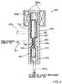
- the selector valve 181 is shown in detail in FIG. 4.
- the selector valve 181 is provided with a selector valve body 190 that is actuated by a solenoid 199a.
- the selector valve 181 may include a housing 181a, in which a first chamber 194, a second chamber 195 and a connecting passage 196 for connecting both the chambers are provided.
- a discharge chamber 120 shown in FIG. 3 communicates with the connecting passage 196 through the selector valve guide passage 187.
- the heating circuit refrigerant release valve 185 shown in FIG. 3 communicates with the first chamber 194 through the heating circuit refrigerant release passage 301a.
- the cooling circuit refrigerant release valve 183 shown in FIG. 3 communicates with the second chamber 195 through the cooling circuit refrigerant release passage 201a.
- the selector valve body 190 may include a first valve body 191, a second valve body 192 and a connecting member 193 for integrally connecting both the valves.
- the first valve body 191 is provided in the first chamber 194 in the housing 181a
- the second valve body 192 is provided in the second chamber 195 in the housing 181a.
- the connecting member 193 is provided in the connecting passage 196 that connect the first chamber 195 with the second chamber 195.
- the selector valve body 190 is movable in a vertical direction in FIG. 4 by exciting/not exciting the solenoid 199a while receiving biasing forces of a spring 199b and a spring 199c.
- the selector valve 181 is operated based upon the control signal of the controller 189 shown in FIG. 7.
- the selector valve body 190 is moved to a lower position.
- the first valve body 191 contacts the first valve seat 197 such that the first chamber 194 does not communicate with the second chamber 195. Therefore, the discharge chamber 120 shown in FIG. 3 communicates with the second chamber 195 through the connecting passage 196 and does not communicate with the first chamber 194.
- the discharge chamber 120 shown in FIG. 3 only communicates with the cooling circuit refrigerant release valve 183 through the selector valve guide passage 187, the second chamber 195 in the selector valve 181 and the first cooling circuit refrigerant release passage 201a.
- the selector valve body 190 is moved to an upper position.
- the second valve body 192 contacts the second valve seat 198 such that the first chamber 194 does not communicate with the second chamber 195. Therefore, the discharge chamber 120 shown in FIG. 3 communicates with the first chamber 194 through the connecting passage 196 and does not communicate with the second chamber 195.
- the discharge chamber 120 shown in FIG. 3 communicates with the heating circuit refrigerant release valve 185 through the selector valve guide passage 187, the first chamber 194 in the selector valve 181, and the first heating circuit refrigerant release passage 301a.
- the selector valve 190 is moved to an intermediate position.
- the first valve body 191 and the second valve body 192 do not contact the first valve seat 197 and the second valve seat 198.
- the first chamber 194 communicates with the second chamber 195.
- the discharge chamber 120 shown in FIG. 3 communicates with the first chamber 194 and the second chamber 195 through the connecting passage 196.
- the selector valve body 190 is moved to a lower position as shown in FIG.4 and the discharge chamber 120 communicates with the cooling circuit refrigerant release valve 183 while the discharge chamber 120 does not communicate with the heating circuit refrigerant release valve 185.
- the refrigerant in the discharge chamber 120 is sent to the cooling circuit refrigerant release valve 183 through the selector valve guide passage 187, the selector valve 181 and the first cooling circuit refrigerant release passage 201a.
- the controller 189 detects the suction pressure Ps value of the compressor and transmits the control signal to open or to close the cooling circuit refrigerant release valve 183 based upon the detected Ps value.
- the suction pressure Ps is in a predetermined low-pressure state, i.e., the suction pressure Ps is abnormally low
- the cooling circuit refrigerant release valve 183 is opened to release the refrigerant from the discharge chamber 120 into the driving chamber 110 through the first and second cooling circuit refrigerant release passages 201a, 201b.
- the pressure in the driving chamber 110 increases, the output discharge capacity of the compressor 101 decreases and the suction pressure Ps increases.
- the heat exchanger 159 see FIG.
- the cooling circuit refrigerant release valve 183 is kept to be closed. As described above, because the selector valve 181 does not connect the discharge chamber 120 with the heating circuit refrigerant release valve 185 during operation of the cooling circuit 151, the refrigerant is not sent to the heating refrigerant release valve 185.
- the cooling refrigerant release valve 183 is opened at all times by the control signal of the controller 189 shown in Fig. 7.
- the selector valve 181 connects the discharge chamber 120 with the heating circuit refrigerant release valve 185 and does not connect the discharge chamber 120 with the cooling circuit refrigerant release valve 183 as shown in FIG.5.
- the selector valve 181 is operated based upon the control signal of the controller 189 shown in FIG. 7. Therefore, as shown in FIG.
- the refrigerant in the discharge chamber 120 is sent to the heating refrigerant release valve. 185 through the selector valve guide passage 187, the selector valve 181 and the first heating circuit refrigerant release passage 301a.
- a differential pressure valve is utilized for the heating circuit refrigerant release valve 185.
- the heating circuit refrigerant release valve 185 is opened by the difference between the pressure in the first heating circuit refrigerant release passage 301a and the pressure in the second heating circuit refrigerant release passage 301b.
- the heating circuit refrigerant release valve 185 opens when the difference between the discharge pressure Pd and the pressure in the driving chamber 110 reaches a predetermined value and closes when the difference does not reach the predetermined value.
- the condition for opening the heating circuit refrigerant release valve 185 may be determined by adjusting the biasing force of the spring 305 shown in FIG. 3. The difference between the discharge pressure Pd and the pressure Pc in the driving chamber 110 does not increase to open the heating circuit refrigerant release valve 185 when the discharge pressure Pd is not in the predetermined high-pressure state.
- the discharge chamber 120 is not connected to the driving chamber 110 and the refrigerant in the discharge chamber 120 is not released into the driving chamber 110 when the discharge pressure Pd is not abnormally high.
- the cooling circuit refrigerant release valve 183 is opened in such a case, the refrigerant is not released into the driving chamber 110 by the cooling circuit refrigerant release valve 183 because the selector valve 181 does not communicate the discharge chamber 120 with the cooling circuit refrigerant release valve 183.
- the selector valve body 190 connects both the first chamber 194 and the second chamber 195 with the discharge chamber 120 as shown in FIG. 6.
- the discharge chamber 120 is connected to both the heating circuit refrigerant release valve 185 and the cooling circuit refrigerant release valve 183.
- the heating circuit refrigerant release valve 185 is opened by the difference between the discharge pressure Pd and the pressure Pc because the discharge pressure Pd increases with respect to the pressure Pc in the driving chamber 110.
- the refrigerant is released from the discharge chamber 120 into the driving chamber 110 through the selector valve 181, the first heating circuit refrigerant release passage 301a, the heating circuit refrigerant release valve 185 and the second heating circuit refrigerant release passage 301b.
- the cooling circuit refrigerant release valve 183 is opened at all times during operation of the heating circuit 152, the refrigerant is also released from the discharge chamber 120 into the driving chamber 110 through the selector valve 181, the first cooling circuit refrigerant release passage 201a, the cooling circuit refrigerant release valve 183 and the second cooling circuit refrigerant release passage 201b.
- the cooling circuit refrigerant release valve 183 is opened at all times during operation of the heating circuit, the refrigerant can immediately be released from the discharge port 120 into the driving chamber 110 for alleviating the abnormally high discharge pressure through the cooling circuit refrigerant release valve 183 by only changing the selector valve 181 from the state shown in FIG.5 to the state shown in FIG.6.
- the pressure Pc in the driving chamber increases, the swash plate 130 shown in FIG. 3 stands (the inclination angle decreases), the piston stroke decreases, and the output discharge capacity decreases.
- the discharge pressure Pd of the refrigerant decreases and the abnormally high-pressure state of the discharge pressure Pd can be alleviated.
- the abnormally high discharge pressure Pd can quickly be alleviated even if the discharge pressure Pd increases relatively sharply in a short time during operation of the heating circuit.
- energy efficiency is slightly decreased because the compressor 101 releases the compressed refrigerant into the driving chamber 110.
- the output discharge capacity of the compressor 101 is decreased by a small release amount of the refrigerant. Therefore, the loss of energy efficiency for alleviating the abnormal high discharge pressure can be minimized
- the refrigerant released into the driving chamber 110 is drawn into the cylinder bores 109 through the bleeding passage 105, the suction chamber 115, the suction port 118a and the suction valve 118 and then re-compressed and discharged through the discharge port 123a, the discharge valve 123, the discharge chamber 120 and the discharge opening 121.
- the heating circuit refrigerant release valve 185 may be utilized for releasing the refrigerant from the discharge port 120 into the driving chamber 110 by operating the selector valve 181, the refrigerant can quickly be released for alleviating the abnormal high discharge pressure during operation of the heating circuit 152.
- the selector valve 381 is provided downstream the cooling circuit refrigerant release valve 385 and the heating circuit refrigerant release valve 383 as shown in FIG.8. Because structures of the respective devices are the same as those described in the first embodiment, detailed description thereof will be omitted.
- the refrigerant in the discharge chamber 120 is sent to the cooling circuit refrigerant release valve 383 through the first cooling circuit refrigerant release passage 383a and also sent to the heating circuit refrigerant release valve 385 through the first heating circuit refrigerant releasing passage 385a during the operation of both the cooling circuit and heating circuit.
- the cooling circuit refrigerant release valve 383 is opened by the control signal from the controller 389.
- the selector valve 381 connects the second cooling circuit refrigerant release passage 383b with the selector valve guide passage 387, while the selector valve 381 does not connect the second heating circuit refrigerant release passage 385b with the selector valve guide passage 387.
- the refrigerant in the discharge chamber 120 is released into the driving chamber 110 through the first cooling circuit refrigerant release passage 383a, the cooling circuit refrigerant release valve 383, the second cooling circuit refrigerant release passage 383b, the selector valve 381 and the selector valve guide passage 387.
- the cooling circuit refrigerant release valve 383 is kept to be opened at all times.
- the selector valve 381 connects the second heating circuit refrigerant release passage 385b with the selector valve guide passage 387, while the selector valve 381 does not connect the second cooling circuit refrigerant release passage 383b with the selector valve guide passage 387.
- the difference between the discharge pressure Pd and the pressure Pc in the driving chamber 110 does not reach the value to open the heating circuit refrigerant release valve 385. Therefore, the refrigerant is not released from the discharge chamber 120 into the driving chamber 110 when the discharge pressure Pd is not in the abnormally high-pressure state during operation of the heating circuit.
- the selector valve 381 connects the second heating circuit refrigerant release passage 385b with the selector valve guide passage 387 and also connects the first cooling circuit refrigerant release passage 383b with the selector valve guide passage 387.
- the heating refrigerant release valve 385 is opened by the difference between the discharge pressure Pd and the pressure Pc in the driving chamber 110.
- the cooling refrigerant release valve 383 is opened at all times during operation of the heating circuit.
- the refrigerant is released from the discharge chamber 120 into the driving chamber 110 through the two passages, i.e., the heating circuit refrigerant release passage 385a, 385b and the cooling circuit refrigerant release passage 383a, 383b.
- the cooling circuit refrigerant release valve 183 is opened based on a value related to change in the discharge pressure.
- a one-time (discharge pressure increasing speed) or a multiple-time differential value such as a two-time differential value (discharge pressure increasing acceleration) can be utilized.
- the discharge pressure increasing speed one-time differential value of the discharge pressure
- the discharge pressure will increase drastically when the discharge pressure increasing speed exceeds the predetermined value. Therefore, it is possible to control the opening degree of the cooling circuit refrigerant release valve in response to the discharge pressure increasing speed.
- the selector valve, the cooling circuit refrigerant release valve and the heating circuit refrigerant release valve are disposed within the housing of the compressor.
- these devices can be provided outside the compressor in part or in whole.
- a one-sided swash plate type of compressor i.e., a compressor having pistons 171 disposed on only one side of the swash plate 161 in FIG.3, is_utilized as the variable displacement compressor in above-described representative embodiments.
- a double-ended piston type can also be utilized in the variable displacement compressor, in which pistons are connected to opposite sides of the swash plate for reciprocation.
- cooling circuit refrigerant release valve is the solenoid valve that is opened by the solenoid and the heating circuit refrigerant release valve is the differential pressure valve that is opened by the difference between the two pressure
- both the valves may be the solenoid valves or may be the differential pressure valves.
- the differential pressure valve may utilize the discharge pressure Pd as the high-pressure side and may utilize the suction pressure Ps, the driving chamber pressure Pc, a vacuum pressure or an atmospheric pressure as the low-side pressure.
- the air conditioning system was described as having both a cooling circuit and a heating circuit in the representative embodiments, the cooling circuit may be removed, because the present teachings are preferably utilized to alleviate high pressure state within the heating circuit.
- An air conditioning system 100 may include a compressor 101 having a driving chamber110, a cooling circuit 151, a heating circuit 152 and a controller 189. This system may release high pressure refrigerant from the compressor discharge port 120 into the compressor driving chamber 110 by means of the controller 189.
- the controller 189 may include a selector 181, a first refrigerant releasing means 183 and a second refrigerant releasing means 185.
- the selector 181 connects the discharge port 120 and the driving chamber 110 by both the first and second refrigerant releasing means 183, 185 when discharge pressure of the refrigerant has reached a predetermined high-pressure state during operation of the heating circuit 152.
- the high pressure refrigerant is released from the discharge port 120 into the driving chamber 110 not only by a single refrigerant releasing means 185 but by double refrigerant releasing means 183, 185. Therefore, the high pressure refrigerant can be swiftly released into the driving chamber 110 to increase the pressure in the driving chamber 110 and the necessary time for reducing the compressor discharge pressure can be minimized. Thus, the abnormal high discharge pressure can be quickly alleviated.
Description
- The present invention relates to air conditioning systems that utilize refrigerants and a compressor, and particularly to air conditioning systems capable of alleviating excessive increases in refrigerant discharge pressure within a heating circuit.
- A known air conditioning system is disclosed in Japanese Patent Application No. 7-19630 and includes a
compressor 1, acooling circuit 51, aheating circuit 52 and acontroller 83, as shown in FIG. 1. Thecooling circuit 51 includes acondenser 55, afirst expansion valve 57 and aheat exchanger 59 provided on a passage connecting a discharge port D to a suction port S of thecompressor 1. High temperature and high pressure refrigerant discharged from the discharge port D of thecompressor 1 is drawn through the above respective devices and back to thecompressor 1. - The
heating circuit 52 includes abypass passage 52a that extends from the discharge port D of thecompressor 1 to theheat exchanger 59, asecond expansion valve 63 provided within thebypass passage 52a and theheat exchanger 59. The high temperature and high pressure refrigerant discharged from thecompressor 1 is not directed to thecondenser 55, but rather is drawn by thecompressor 1 through thesecond expansion valve 63 and theheat exchanger 59. Such aheating circuit 52 is generally known as a hot gas bypass heater. - The operation of the
cooling circuit 51 and theheating circuit 52 is changeably selected by opening andclosing selector valves 53a and 53b, which opening and closing operations are performed by thecontroller 83. - Because the refrigerant discharge pressure is higher when the
heating circuit 52 is used than when thecooling circuit 51 is used, the air conditioning system must operate in a high pressure state when theheating circuit 52 is utilized. An abnormally high-pressure state may be created if the output discharge capacity of thecompressor 1 temporarily increases during the operation of theheating circuit 52. Arefrigerant releasing passage 91 having apressure relief valve 93 is provided in order to release excess pressure fromheating circuit 52, if an abnormally high pressure state is reached. Therefrigerant releasing passage 91 is connected to theheating circuit 52 and thecooling circuit 51 and thepressure relief valve 93 can be opened to release the refrigerant from theheating circuit 52 into thecooling circuit 51 when the refrigerant discharge pressure abnormally increases during the operation of theheating circuit 52. - Another known variable displacement compressor is disclosed in Japanese Patent Application No.10-47242. Although this compressor is not explicitly shown in the drawings, a connecting passage having a capacity control valve is provided between a discharge port and a driving chamber (also known as the crank case) in a housing such that refrigerant is released from the discharge port into the driving chamber when the capacity control valve is opened. The capacity control valve is opened to increase the pressure in the driving chamber when the discharge pressure is high. On the other hand, the capacity control valve is closed to decrease the pressure in the driving chamber when the discharge pressure is low.
- The output discharge capacity is decreased when the pressure in the driving chamber is increased, and the output discharge capacity is increased when the pressure in the driving chamber is decreased. The output discharge capacity is decreased to decrease the discharge pressure when the discharge pressure increases, and the output discharge capacity is increased to increase the discharge pressure when the discharge pressure decreases.
- If the variable displacement compressor disclosed in Japanese Patent Application No.10-47242 is employed in the air conditioning system having the hot gas bypass heater circuit disclosed in Japanese Patent Application No.7-19630, abnormally high pressure can be alleviated without the insufficiency in the heating performance due to release of the refrigerant in the hot gas bypass heater circuit into the cooling circuit and without low energy sufficiency due to wasteful release of the refrigerant at highly increased pressure by causing the compressor to work.
- However, a problem can occur due to a combination of a characteristics of the variable displacement compressor and a characteristics of the hot gas bypass heater by only employing the variable displacement compressor disclosed in Japanese Patent Application No.10-47242 in the air conditioning system having the hot gas bypass heater circuit disclosed in Japanese Patent Application No.7-19630. As described above, because a step of decreasing the opening the capacity control valve of the compressor to increase the pressure in the driving chamber, a step of decreasing the output discharge capacity and a step of decreasing the discharge pressure are necessary to alleviate the abnormal high discharge pressure by utilizing the technique disclosed in Japanese Patent Application No. 10-47242.
- Therefore, if the discharge pressure increases drastically, the discharge pressure may abnormally be increased and the hot gas bypass heater circuit may be damaged by such abnormal increase in pressure because above-explained steps for decreasing the discharge pressure by decreasing the pressure in the driving chamber of the variable displacement compressor require certain time to be completed.
- The technique disclosed in Japanese Patent Application No.10-47242 does not have a hot gas bypass heater circuit and has only the cooling circuit. In such a case, the pressure of the refrigerant flowing through the cooling circuit is inherently lower than the pressure of the refrigerant flowing through the hot gas bypass heater circuit, and the cooling circuit may not be damaged by abnormal increase in pressure.
- In other words, the technique disclosed in Japanese Patent Application No.10-47242 is sufficient when the hot gas bypass heater circuit is not employed. However, if the air conditioning system has the hot gas bypass heater circuit, because the pressure of the refrigerant during the operation of the hot gas bypass heater circuit is inherently high, the output discharge capacity control technique of the known variable displacement compressor is insufficient to quickly alleviate the abnormal increase in pressure.
- Document EP-0 486 257 A1 discloses a slant plate type compressor with a variable capacity control mechanism. In this compressor a piston is slidably fitted within each of the cylinders and is reciprocated by a drive mechanism which includes a slant plate having a surface with an adjustable incline angle. The incline angle and thus the capacity of the compressor is controlled according to the pressure differential between the crank chamber and a suction chamber. The pressure in either the crank chamber or the suction chamber is controlled by an externally controlled valve mechanism which is disposed in a passageway linking the crank chamber and the suction chamber. An internally controlled safety valve device prevents an abnormal pressure differential between the crank and suction chambers.
- It is, therefore, an object of the present invention to provide an air conditioning system that can alleviate abnormal high pressure state more quickly.
- Preferably, an air conditioning system may include a compressor having a driving chamber, a cooling circuit, a heating circuit and a controller. This system may release high pressure refrigerant from the compressor discharge port into the compressor driving chamber by means of a controller. By increasing the pressure within the driving chamber, the compressor discharge capacity can be reduced, because the compressor stroke length will be decreased. As a result, the pressure within the air conditioning system will be reduced by the reduction in the compressor discharge capacity.
- The controller may include a selector, a first refrigerant releasing means and a second refrigerant releasing means. The selector connects the discharge port and the driving chamber by both the first and second refrigerant releasing means when discharge pressure of the refrigerant has reached a predetermined high-pressure state during operation of the heating circuit. This is, when the discharge pressure of the refrigerant results an abnormal high pressure state during the operation of the heating circuit, the high pressure refrigerant is released from the discharge port into the driving chamber not only by a single refrigerant releasing means but by double refrigerant releasing means. Therefore, the high pressure refrigerant can be swiftly released into the driving chamber to increase the pressure in the driving chamber and the necessary time for reducing the compressor discharge pressure can be minimized. Thus, the abnormal high pressure state of the discharged refrigerant can be quickly alleviated.
- Other objects, features and advantages of the present invention will be readily understood after reading the following detailed description together with the accompanying drawings and the claims.
-
- FIG. 1 shows a known air conditioning system.
- FIG. 2 shows an air conditioning system according to a first representative embodiment.
- FIG. 3 shows the detailed constructions of a compressor and controller in the air conditioning system according to the first representative embodiment.
- FIGS. 4 to 6 respectively show the detailed constructions of a selector valve.
- FIG. 7 shows the schematic construction of the controller.
- FIG. 8 shows the schematic construction of the controller according to the second representative embodiment.
-
- Preferably, an air conditioning system includes a compressor, a heating circuit and a controller. The compressor may have a driving unit provided in a driving chamber, a suction port for drawing refrigerant into the compressor and a discharge port for discharging high pressure refrigerant from the compressor. The controller decreases the output discharge capacity of the compressor by releasing the refrigerant from the discharge port into the driving chamber. The heating circuit may have a passage that extends from the discharge port to the suction port through the heat exchanger. Such a heating circuit is generally known as a hot gas bypass heater. It is preferable to provide a decompressor such as an expansion valve on the bypass passage that extends from the discharge port to the heat exchanger in the hot gas bypass heater. The controller may have a selector and a first refrigerant releasing means and a second refrigerant releasing means for connecting separately the discharge port and the driving chamber.
- The selector may connect the discharge port and the driving chamber by both the first and second refrigerant releasing means when discharge pressure of the refrigerant results a predetermined high-pressure state during operation of the heating circuit.
- In this example, the controller may release the high pressure refrigerant from the discharge port into the driving chamber to increase the pressure in the driving chamber. When the pressure in the driving chamber increases, the compressor output discharge capacity decreases. When the pressure in the driving chamber decreases, the compressor output discharge capacity increases. When the output discharge capacity decreases, the discharge pressure of the compressor decreases and the suction pressure of the compressor increases. When the output discharge capacity increases, the discharge pressure increases and the suction pressure decreases.
- When the discharge pressure results an abnormal high-pressure state during operation of the heating circuit, the heating circuit will be damaged because high pressure is utilized in operating the heating circuit to attain sufficient heating performance and therefore, an upper limit tolerance level for the discharge pressure becomes closer in the heating circuit. Particularly, such an abnormal high pressure of the refrigerant will seriously damage the hot gas bypass heater circuit because the circuit capacity for flowing the refrigerant in the hot gas bypass heater is smaller than the capacity of a general type of heating circuit such as a heat pomp. Therefore, the selector may connect the discharge port and the driving chamber by both the first and second refrigerant releasing means when discharge pressure of the refrigerant results a predetermined high-pressure state during operation of the heating circuit. This is, the high pressure refrigerant can be quickly released into the driving chamber by using both the first and second refrigerant releasing means and thus, the output discharge capacity of the compressor quickly decreases. As a result, even if the discharge pressure increases rapidly, the abnormal high pressure state of the refrigerant can be quickly alleviated.
- The selector may preferably include a valve that can select the first and second refrigerant releasing means for releasing the refrigerant from the discharge port into the driving chamber. In such a case, this valve is, for example, the feature corresponding to the selector as described above, while the interpretation of the term "selector" is not limited within this valve.
- The first refrigerant releasing means may preferably include a first valve that is provided on a first passage extending from the discharge port to the driving chamber. In such a case, for example, the first valve and the first passage are the features corresponding to the first refrigerant releasing means as described above, while the interpretation of the term "first refrigerant releasing means" is not limited within the first valve and the first passage. The first valve may open for communicating the first passage when the compressor suction pressure results the predetermined low-pressure state during the operation of the cooling circuit. Further, the first valve may open when the compressor discharge pressure results the predetermined high-pressure state during the operation of the heating circuit.
- The second refrigerant releasing means may preferably include a second valve that is provided on a second passage extending from the discharge port to the driving chamber. In such a case, for example, the second valve and the second passage are the features corresponding to the second refrigerant releasing means as described above, while the interpretation of the term "second refrigerant releasing means" is not limited within the second valve and the second passage". The second valve may be opened for communicating the second passage when the compressor discharge pressure results the predetermined high-pressure state during the operation of the heating circuit. According to such an example, the selector valve may open both the first and second passages so that the refrigerant may be released from the discharge port into the driving chamber through both the first and second passages. Therefore, the abnormal high-pressure state of the compressor discharge pressure during the operation of the heating circuit can be quickly alleviated because of the quick release of the refrigerant from the discharge port into the driving chamber by using two passages.
- Moreover, the selector valve may be provided on a passage extending from the discharge port to the first and second valves or the selector valve may be provided on a passage extending from the first and second valve to the driving chamber.
- In a second representative example, the first valve is opened at all times during operation of the heating circuit. When the selector valve is opened to communicate both the first and second passages for the alleviation of the abnormal high-pressure state of the discharge pressure during operation of the heating circuit, the refrigerant can be released more quickly because the first valve is already opened when the selector valve communicates the first passage.
- Each of the additional features and method steps disclosed above and below may be utilized separately or in conjunction with other features and method steps to provide improved air conditioning systems and methods for designing and using such air conditioning systems. Representative examples of the present invention, which examples utilize many of these additional features and method steps in conjunction, will now be described in detail with reference to the drawings. This detailed description is merely intended to teach a person of skill in the art further details for practicing preferred aspects of the present teachings and is not intended to limit the scope of the invention. Only the claims define the scope of the claimed invention. Therefore, combinations of features and steps disclosed in the following detail description may not be necessary to practice the invention in the broadest sense, and are instead taught merely to particularly describe some representative examples of the invention, which detailed description will now be given with reference to the accompanying drawings.
- Referring to Fig. 2, the
air conditioning system 100 may include acooling circuit 151, aheating circuit 152 and avariable displacement compressor 101 as a driving source for both the heating and cooling circuits. A representative controller is shown in FIGS. 3 and 4, but is not shown in FIG. 2 for the sake of convenience and will be described below in further detail. Such anair conditioning system 100 may be utilized in a vehicle-mounted air conditioning system. In such case, thecompressor driving shaft 125 may be coupled to and driven by anautomobile engine 170. - The
cooling circuit 151 may be driven by high-pressure refrigerant, which is compressed by thecompressor 101, and may include acondenser 155, afirst expansion valve 157, aheat exchanger 159 and anaccumulator 161. These devices may be disposed within apath 151a that extends from a discharge port D to a suction port S of thecompressor 101. Theheat exchanger 159 is also generally known as an evaporator. Theheat exchanger 159 may be arranged side by side with a hot-water heater 171, which circulates hot coolant from theengine 170 through apipe 173. - The
heating circuit 152 may be driven by high-temperature and high-pressure refrigerant, which is also compressed by thecompressor 101, and may include asecond expansion valve 163, theheat exchanger 159 and theaccumulator 161. These devices are disposed on abypass passage 152a for introducing the refrigerant discharged from the discharge port D to theheat exchanger 159. In other words, theheating circuit 152 partially overlaps with thecooling circuit 151. Such aheating circuit 152 is also generally known as a hot-gas bypass heater. - In FIG. 2, a first open/
close valve 153a and a second open/close valve 153b may be utilized as switch valves for alternatively actuating thecooling circuit 151 and theheating circuit 152. - During operation of the
cooling circuit 151, the refrigerant is compressed by thecompressor 101 to attain a high temperature and high pressure state. This compressed refrigerant is sent to thecondenser 155, where heat from the high-temperature refrigerant is dissipated to the outside environment and the refrigerant is liquefied. The refrigerant is decompressed by thefirst expansion valve 157 and sent to theheat exchanger 159 where the refrigerant absorbs outside heat and is gasified. The gasified refrigerant is returned to thecompressor 101 again through theaccumulator 161 for re-circulation throughout thesystem 100. - During operation of the
heating circuit 152, the refrigerant is compressed by thecompressor 101 to attain a high temperature and high pressure state. The compressed refrigerant is then decompressed by thesecond expansion valve 163 and sent to theheat exchanger 159, where heat from the compressed refrigerant is dissipated to the outside environment. In the heating circuit cycle, the refrigerant is constantly in a gaseous state while circulating through theheating circuit 152. - The
heating circuit 152 may be used as an auxiliary heater. Heat generated by theheat exchanger 159 during operation of theheating circuit 152 may be used as an auxiliary heating source for thehot water heater 171. Theheating circuit 152 also may be used to assist the coolant from theengine 170 when the coolant can not provide sufficient heat to start theengine 170 in a low-temperature environment, such as an outside air temperature of -20 °C or so. - Referring to FIG. 3, a
representative compressor 101 is shown that may include a drivingchamber 110 defined within ahousing 101a of thecompressor 101 and aswash plate 130 that is rotatably supported by the drivingshaft 125 in the drivingchamber 110. Theswash plate 130 may be supported by the drivingshaft 125 and may rotate together with thedrive shaft 125. Theswash plate 130 is inclined with respect to the drivingshaft 125 when the drivingshaft 125 rotates and the inclination angle of theswash plate 130 with respect to a plane perpendicular to the axis of rotation of the drivingshaft 125 is changeable. - The peripheral edge portion of the
swash plate 130 may be connected to the base portions of the pistons 135 by means ofmovable shoes 131. Six pistons 135 in total may be disposed around the driving shaft,125 (however, only one piston is shown in FIG. 3 for the sake of convenience) and may be laterally slide within six cylinder bores 109. The circumferential positions of the six cylinder bores 109 fixed by thecompressor housing 101a. - When the
swash plate 130 rotates together with the drivingshaft 125 while being inclined as shown in FIG. 3, the peripheral edge of theswash plate 130 slides with respect to the piston 135 fixed in the circumferential direction. When the peripheral edge of theswash plate 130 being inclined to a position closest to the cylinder bores 109 (as shown in FIG. 3), the piston 135 reaches its deepest insertion into the cylinder bores 109. When the peripheral edge of the swash plate 130 (the peripheral edge shown in a lower part of FIG. 3) being inclined to a position furthest away from the cylinder bores 109, the piston 135 is substantially withdrawn from thecylinder bore 109. Each 360° rotation of the drivingshaft 125 results in each piston 135 laterally reciprocating one time. - A suction port 118a and a discharge port 123a are defined in a bottom portion of each the
cylinder bore 109. A suction valve 118 is positioned to correspond to the suction port 118a and adischarge valve 123 is positioned to correspond to the discharge port 123a. Each suction port 118a communicates with asuction chamber 115 and each the discharge port 123a communicates with adischarge chamber 120. - When the piston 135 moves to the left in FIG. 3, as a result of rotation of the
swash plate 130, refrigerant is introduced from thesuction opening 116 through thesuction chamber 115, suction port 118a and suction valve 118 into thecylinder bore 109. When the piston 135 moves to the right in FIG. 3, as a result of further rotation of theswash plate 130, the refrigerant is compressed into a high-pressure state and discharged from adischarge opening 121 through the discharge port 123a,discharge valve 123 anddischarge chamber 120. - The output discharge capacity of the
compressor 101 is determined by the stroke length of the piston 135, which is determined by the degree of change in inclination angle of theswash plate 130 during each cycle. That is, the further theswash plate 130 is withdrawn from the cylinder bore 109 during each cycle, the longer the stroke length of the piston 135 will be. As the stroke length increases, the output discharge capacity of thecompressor 101 also increases. - The inclination angle of the
swash plate 130 is determined, in part, by the difference in pressure on the opposite sides of the piston 135, i.e., the pressure difference between driving chamber pressure and the cylinder bore pressure. Increasing or decreasing the driving chamber pressure can adjust this pressure difference. - The driving
chamber 110 is connected to thesuction chamber 115 through the bleedingpassage 105. Although it is not particularly shown in FIG.3, a throttle is provided in the bleedingpassage 105. - Thus, in order to decrease the output discharge capacity, the high-pressure refrigerant is released from the
discharge chamber 120 into the drivingchamber 110. Due to resulting increase in the driving chamber pressure, theswash plate 130 stands and the stroke length of the piston 135 decreases. Therefore, the output discharge capacity also will decrease. On the other hand, in order to increase the output discharge capacity, the refrigerant in thedischarge chamber 120 is prevented from being released into the drivingchamber 110. As a result, the driving chamber pressure will gradually decrease, theswash plate 130 will move further in the lateral direction and the stroke length of the piston 135 will increase. In this case, the output discharge capacity will increase. - A controller is provided for releasing the high-pressure refrigerant from the
discharge chamber 120 into the drivingchamber 110. The controller may include aselector valve 181, a cooling circuitrefrigerant release valve 183, a heating circuitrefrigerant release valve 185, a selectorvalve guide passage 187, cooling circuit refrigerant release passages 201, heating circuit refrigerant release passages 301 and ableeding passage 105 connecting the drivingchamber 110 to thesuction chamber 115. - The
selector valve 181 communicates with thedischarge chamber 120 through the selectorvalve guide passage 187, with the cooling circuitrefrigerant release valve 183 through the first cooling circuitrefrigerant release passage 201a, and with the heating circuitrefrigerant release valve 185 through the first heating circuitrefrigerant release passage 301a. - The cooling circuit
refrigerant release valve 183 further communicates with the drivingchamber 110 through the second cooling circuit refrigerant release passage 201b. The cooling circuitrefrigerant release valve 183 detects suction pressure Ps in thesuction chamber 115 through a suctionpressure detecting passage 203. The cooling circuitrefrigerant release valve 183 may include avalve body 205 that is opened/closed by exciting/not exciting asolenoid 207. When the cooling circuitrefrigerant release valve 183 opens, the first cooling circuitrefrigerant release passage 201a communicates with the second cooling circuit refrigerant release passage 201b. Thesolenoid 207 is excited by a control signal of controller (not shown in FIG. 3). - The heating circuit
refrigerant release valve 185 further communicates with the drivingchamber 110 through the second heating circuitrefrigerant release passage 301b. The heating circuitrefrigerant release valve 185 may include avalve body 303 that biased downward in FIG. 3 by aspring 305. Thevalve body 303 is a differential pressure valve that is opened by a difference between pressure in the first heating circuitrefrigerant release passage 301a and pressure in the second heating circuit refrigerant release passage 302b. - The
selector valve 181 is shown in detail in FIG. 4. Theselector valve 181 is provided with aselector valve body 190 that is actuated by asolenoid 199a. - The
selector valve 181 may include ahousing 181a, in which afirst chamber 194, asecond chamber 195 and a connectingpassage 196 for connecting both the chambers are provided. Adischarge chamber 120 shown in FIG. 3 communicates with the connectingpassage 196 through the selectorvalve guide passage 187. The heating circuitrefrigerant release valve 185 shown in FIG. 3 communicates with thefirst chamber 194 through the heating circuitrefrigerant release passage 301a. The cooling circuitrefrigerant release valve 183 shown in FIG. 3 communicates with thesecond chamber 195 through the cooling circuitrefrigerant release passage 201a. - The
selector valve body 190 may include afirst valve body 191, asecond valve body 192 and a connectingmember 193 for integrally connecting both the valves. Thefirst valve body 191 is provided in thefirst chamber 194 in thehousing 181a, and thesecond valve body 192 is provided in thesecond chamber 195 in thehousing 181a. The connectingmember 193 is provided in the connectingpassage 196 that connect thefirst chamber 195 with thesecond chamber 195. Theselector valve body 190 is movable in a vertical direction in FIG. 4 by exciting/not exciting thesolenoid 199a while receiving biasing forces of aspring 199b and aspring 199c. Theselector valve 181 is operated based upon the control signal of thecontroller 189 shown in FIG. 7. - In FIG. 4, the
selector valve body 190 is moved to a lower position. In this state, thefirst valve body 191 contacts thefirst valve seat 197 such that thefirst chamber 194 does not communicate with thesecond chamber 195. Therefore, thedischarge chamber 120 shown in FIG. 3 communicates with thesecond chamber 195 through the connectingpassage 196 and does not communicate with thefirst chamber 194. As a result, thedischarge chamber 120 shown in FIG. 3 only communicates with the cooling circuitrefrigerant release valve 183 through the selectorvalve guide passage 187, thesecond chamber 195 in theselector valve 181 and the first cooling circuitrefrigerant release passage 201a. - In FIG. 5, the
selector valve body 190 is moved to an upper position. In this state, thesecond valve body 192 contacts thesecond valve seat 198 such that thefirst chamber 194 does not communicate with thesecond chamber 195. Therefore, thedischarge chamber 120 shown in FIG. 3 communicates with thefirst chamber 194 through the connectingpassage 196 and does not communicate with thesecond chamber 195. As a result, thedischarge chamber 120 shown in FIG. 3 communicates with the heating circuitrefrigerant release valve 185 through the selectorvalve guide passage 187, thefirst chamber 194 in theselector valve 181, and the first heating circuitrefrigerant release passage 301a. - In FIG. 6, the
selector valve 190 is moved to an intermediate position. In this state, thefirst valve body 191 and thesecond valve body 192 do not contact thefirst valve seat 197 and thesecond valve seat 198. As a result, thefirst chamber 194 communicates with thesecond chamber 195. Therefore, thedischarge chamber 120 shown in FIG. 3 communicates with thefirst chamber 194 and thesecond chamber 195 through the connectingpassage 196. As a result, thedischarge chamber 120 shown in FIG. 3 communicates with the cooling circuitrefrigerant release valve 183 through the selectorvalve guide passage 187, thesecond chamber 195 in theselector valve 181 and the first cooling circuitrefrigerant release passage 201a, while thedischarge chamber 120 communicates with the heating circuitrefrigerant release valve 185 through the selectorvalve guide passage 187, thefirst chamber 194 in theselector valve 181, and the first heating circuitrefrigerant release passage 301a. The above-explained structure is schematically shown in FIG. 7. - During operation of the
cooling circuit 151, theselector valve body 190 is moved to a lower position as shown in FIG.4 and thedischarge chamber 120 communicates with the cooling circuitrefrigerant release valve 183 while thedischarge chamber 120 does not communicate with the heating circuitrefrigerant release valve 185. As shown in FIG. 7, the refrigerant in thedischarge chamber 120 is sent to the cooling circuitrefrigerant release valve 183 through the selectorvalve guide passage 187, theselector valve 181 and the first cooling circuitrefrigerant release passage 201a. - The
controller 189 detects the suction pressure Ps value of the compressor and transmits the control signal to open or to close the cooling circuitrefrigerant release valve 183 based upon the detected Ps value. When the suction pressure Ps is in a predetermined low-pressure state, i.e., the suction pressure Ps is abnormally low, during operation of thecooling circuit 151, the cooling circuitrefrigerant release valve 183 is opened to release the refrigerant from thedischarge chamber 120 into the drivingchamber 110 through the first and second cooling circuitrefrigerant release passages 201a, 201b. Thus, the pressure in the drivingchamber 110 increases, the output discharge capacity of thecompressor 101 decreases and the suction pressure Ps increases. As a result, the heat exchanger 159 (see FIG. 2) can be prevented from being frosted. When the suction pressure Ps is not in a predetermined low-pressure state, i.e., the suction pressure Ps is not excessively low, the cooling circuitrefrigerant release valve 183 is kept to be closed. As described above, because theselector valve 181 does not connect thedischarge chamber 120 with the heating circuitrefrigerant release valve 185 during operation of thecooling circuit 151, the refrigerant is not sent to the heatingrefrigerant release valve 185. - During operation of the
heating circuit 152, the coolingrefrigerant release valve 183 is opened at all times by the control signal of thecontroller 189 shown in Fig. 7. When the discharge pressure Pd of the refrigerant is not in a predetermined high-pressure state, i.e., the discharge pressure Pd is not abnormally high, during operation of theheating circuit 152, theselector valve 181 connects thedischarge chamber 120 with the heating circuitrefrigerant release valve 185 and does not connect thedischarge chamber 120 with the cooling circuitrefrigerant release valve 183 as shown in FIG.5. Theselector valve 181 is operated based upon the control signal of thecontroller 189 shown in FIG. 7. Therefore, as shown in FIG. 7, the refrigerant in thedischarge chamber 120 is sent to the heating refrigerant release valve. 185 through the selectorvalve guide passage 187, theselector valve 181 and the first heating circuitrefrigerant release passage 301a. As described above, a differential pressure valve is utilized for the heating circuitrefrigerant release valve 185. The heating circuitrefrigerant release valve 185 is opened by the difference between the pressure in the first heating circuitrefrigerant release passage 301a and the pressure in the second heating circuitrefrigerant release passage 301b. Because the pressure in the first heating circuitrefrigerant release passage 301a is equal to the discharge pressure Pd, and the pressure in the second heating circuitrefrigerant release passage 301b is equal to the pressure Pc in the drivingchamber 110, the heating circuitrefrigerant release valve 185 opens when the difference between the discharge pressure Pd and the pressure in the drivingchamber 110 reaches a predetermined value and closes when the difference does not reach the predetermined value. The condition for opening the heating circuitrefrigerant release valve 185 may be determined by adjusting the biasing force of thespring 305 shown in FIG. 3. The difference between the discharge pressure Pd and the pressure Pc in the drivingchamber 110 does not increase to open the heating circuitrefrigerant release valve 185 when the discharge pressure Pd is not in the predetermined high-pressure state. Therefore, thedischarge chamber 120 is not connected to the drivingchamber 110 and the refrigerant in thedischarge chamber 120 is not released into the drivingchamber 110 when the discharge pressure Pd is not abnormally high. Although the cooling circuitrefrigerant release valve 183 is opened in such a case, the refrigerant is not released into the drivingchamber 110 by the cooling circuitrefrigerant release valve 183 because theselector valve 181 does not communicate thedischarge chamber 120 with the cooling circuitrefrigerant release valve 183. - When the discharge pressure Pd results the abnormally high-pressure state during operation of the
heating circuit 152, theselector valve body 190 connects both thefirst chamber 194 and thesecond chamber 195 with thedischarge chamber 120 as shown in FIG. 6. Thus, thedischarge chamber 120 is connected to both the heating circuitrefrigerant release valve 185 and the cooling circuitrefrigerant release valve 183. - On the contrary, when the discharge pressure Pd results the predetermined high-pressure state during operation of the
heating circuit 152, the heating circuitrefrigerant release valve 185 is opened by the difference between the discharge pressure Pd and the pressure Pc because the discharge pressure Pd increases with respect to the pressure Pc in the drivingchamber 110. As a result, the refrigerant is released from thedischarge chamber 120 into the drivingchamber 110 through theselector valve 181, the first heating circuitrefrigerant release passage 301a, the heating circuitrefrigerant release valve 185 and the second heating circuitrefrigerant release passage 301b. Further, as described above, because the cooling circuitrefrigerant release valve 183 is opened at all times during operation of theheating circuit 152, the refrigerant is also released from thedischarge chamber 120 into the drivingchamber 110 through theselector valve 181, the first cooling circuitrefrigerant release passage 201a, the cooling circuitrefrigerant release valve 183 and the second cooling circuit refrigerant release passage 201b. - This is, when the discharge pressure Pd of the refrigerant reaches a predetermined high-pressure state during operation of the
heating circuit 152, not only the heating circuit refrigerant release passage 301 but also the cooling circuit refrigerant release passage 201 is utilized for releasing the refrigerant from thedischarge chamber 120 into the drivingchamber 110. Therefore, the abnormal high pressure refrigerant can be quickly released from thedischarge port 120 into the drivingchamber 110 by utilizing two passages. Further, because the cooling circuitrefrigerant release valve 183 is opened at all times during operation of the heating circuit, the refrigerant can immediately be released from thedischarge port 120 into the drivingchamber 110 for alleviating the abnormally high discharge pressure through the cooling circuitrefrigerant release valve 183 by only changing theselector valve 181 from the state shown in FIG.5 to the state shown in FIG.6. - As a result of releasing the refrigerant from the
discharge chamber 120 into the drivingchamber 110, the pressure Pc in the driving chamber increases, theswash plate 130 shown in FIG. 3 stands (the inclination angle decreases), the piston stroke decreases, and the output discharge capacity decreases. Thus, the discharge pressure Pd of the refrigerant decreases and the abnormally high-pressure state of the discharge pressure Pd can be alleviated. As described above, because the refrigerant is released quickly through the two passages, the abnormally high discharge pressure Pd can quickly be alleviated even if the discharge pressure Pd increases relatively sharply in a short time during operation of the heating circuit. - In this embodiment, energy efficiency is slightly decreased because the
compressor 101 releases the compressed refrigerant into the drivingchamber 110. However, the output discharge capacity of thecompressor 101 is decreased by a small release amount of the refrigerant. Therefore, the loss of energy efficiency for alleviating the abnormal high discharge pressure can be minimized - The refrigerant released into the driving
chamber 110 is drawn into the cylinder bores 109 through the bleedingpassage 105, thesuction chamber 115, the suction port 118a and the suction valve 118 and then re-compressed and discharged through the discharge port 123a, thedischarge valve 123, thedischarge chamber 120 and thedischarge opening 121. - According to this embodiment, a problem of shortage of heating performance due to release of the refrigerant in the heating circuit into the cooling circuit does not occur.
- Moreover, because not only the heating circuit
refrigerant release valve 185 but also the cooling circuitrefrigerant release valve 183 may be utilized for releasing the refrigerant from thedischarge port 120 into the drivingchamber 110 by operating theselector valve 181, the refrigerant can quickly be released for alleviating the abnormal high discharge pressure during operation of theheating circuit 152. - In the second representative embodiment, the
selector valve 381 is provided downstream the cooling circuitrefrigerant release valve 385 and the heating circuitrefrigerant release valve 383 as shown in FIG.8. Because structures of the respective devices are the same as those described in the first embodiment, detailed description thereof will be omitted. - Referring to FIG.8, the refrigerant in the
discharge chamber 120 is sent to the cooling circuitrefrigerant release valve 383 through the first cooling circuitrefrigerant release passage 383a and also sent to the heating circuitrefrigerant release valve 385 through the first heating circuit refrigerant releasing passage 385a during the operation of both the cooling circuit and heating circuit. - When the suction pressure Ps value is in an abnormally low-pressure state during operation of the cooling circuit, the cooling circuit
refrigerant release valve 383 is opened by the control signal from thecontroller 389. Theselector valve 381 connects the second cooling circuitrefrigerant release passage 383b with the selectorvalve guide passage 387, while theselector valve 381 does not connect the second heating circuitrefrigerant release passage 385b with the selectorvalve guide passage 387. Therefore, when the suction pressure Ps is in the abnormally low-pressure state during operation of the cooling circuit, the refrigerant in thedischarge chamber 120 is released into the drivingchamber 110 through the first cooling circuitrefrigerant release passage 383a, the cooling circuitrefrigerant release valve 383, the second cooling circuitrefrigerant release passage 383b, theselector valve 381 and the selectorvalve guide passage 387. - During operation of the heating circuit, the cooling circuit
refrigerant release valve 383 is kept to be opened at all times. When the discharge pressure Pd is not in the abnormally high-pressure state during operation of the heating circuit, theselector valve 381 connects the second heating circuitrefrigerant release passage 385b with the selectorvalve guide passage 387, while theselector valve 381 does not connect the second cooling circuitrefrigerant release passage 383b with the selectorvalve guide passage 387. The difference between the discharge pressure Pd and the pressure Pc in the drivingchamber 110 does not reach the value to open the heating circuitrefrigerant release valve 385. Therefore, the refrigerant is not released from thedischarge chamber 120 into the drivingchamber 110 when the discharge pressure Pd is not in the abnormally high-pressure state during operation of the heating circuit. - On the other hand, when the discharge pressure Pd is in the abnormally high-pressure state during operation of the heating circuit, the
selector valve 381 connects the second heating circuitrefrigerant release passage 385b with the selectorvalve guide passage 387 and also connects the first cooling circuitrefrigerant release passage 383b with the selectorvalve guide passage 387. In this case, because the discharge pressure Pd becomes high with respect to the pressure Pc in the drivingchamber 110 enough to open the heating circuitrefrigerant release valve 385. Thus, the heatingrefrigerant release valve 385 is opened by the difference between the discharge pressure Pd and the pressure Pc in the drivingchamber 110. As described above, the coolingrefrigerant release valve 383 is opened at all times during operation of the heating circuit. Therefore, the refrigerant is released from thedischarge chamber 120 into the drivingchamber 110 through the two passages, i.e., the heating circuitrefrigerant release passage 385a, 385b and the cooling circuitrefrigerant release passage - In this representative embodiment, the cooling circuit
refrigerant release valve 183 is opened based on a value related to change in the discharge pressure. Preferably, a one-time (discharge pressure increasing speed) or a multiple-time differential value such as a two-time differential value (discharge pressure increasing acceleration) can be utilized. - It is determined that the discharge pressure will not increase drastically when, for example, the discharge pressure increasing speed (one-time differential value of the discharge pressure) does not exceed the predetermined value. And it is determined that the discharge pressure will increase drastically when the discharge pressure increasing speed exceeds the predetermined value. Therefore, it is possible to control the opening degree of the cooling circuit refrigerant release valve in response to the discharge pressure increasing speed.
- In above-described embodiments, the selector valve, the cooling circuit refrigerant release valve and the heating circuit refrigerant release valve are disposed within the housing of the compressor. However, these devices can be provided outside the compressor in part or in whole. Further, a one-sided swash plate type of compressor, i.e., a
compressor having pistons 171 disposed on only one side of theswash plate 161 in FIG.3, is_utilized as the variable displacement compressor in above-described representative embodiments. However, a double-ended piston type can also be utilized in the variable displacement compressor, in which pistons are connected to opposite sides of the swash plate for reciprocation. Further, although the cooling circuit refrigerant release valve is the solenoid valve that is opened by the solenoid and the heating circuit refrigerant release valve is the differential pressure valve that is opened by the difference between the two pressure, both the valves may be the solenoid valves or may be the differential pressure valves. In such a case, the differential pressure valve may utilize the discharge pressure Pd as the high-pressure side and may utilize the suction pressure Ps, the driving chamber pressure Pc, a vacuum pressure or an atmospheric pressure as the low-side pressure. Further, although the air conditioning system was described as having both a cooling circuit and a heating circuit in the representative embodiments, the cooling circuit may be removed, because the present teachings are preferably utilized to alleviate high pressure state within the heating circuit. - An
air conditioning system 100 may include acompressor 101 having a driving chamber110, acooling circuit 151, aheating circuit 152 and acontroller 189. This system may release high pressure refrigerant from thecompressor discharge port 120 into thecompressor driving chamber 110 by means of thecontroller 189. Thecontroller 189 may include aselector 181, a first refrigerant releasing means 183 and a secondrefrigerant releasing means 185. Theselector 181 connects thedischarge port 120 and the drivingchamber 110 by both the first and second refrigerant releasing means 183, 185 when discharge pressure of the refrigerant has reached a predetermined high-pressure state during operation of theheating circuit 152. When the discharge pressure of the refrigerant results an abnormal high pressure state during the operation of theheating circuit 152, the high pressure refrigerant is released from thedischarge port 120 into the drivingchamber 110 not only by a single refrigerant releasing means 185 but by double refrigerant releasing means 183, 185. Therefore, the high pressure refrigerant can be swiftly released into the drivingchamber 110 to increase the pressure in the drivingchamber 110 and the necessary time for reducing the compressor discharge pressure can be minimized. Thus, the abnormal high discharge pressure can be quickly alleviated.
Claims (22)
- An air conditioning system (100) comprising:characterized in that the selector (181, 381) connects the discharge port (D) to the driving chamber (110) by both the first and second refrigerant releasing means (183, 185, 201b, 301b) when the compressor (101) discharge pressure (Pd) results a predetermined high-pressure state during the operation of the heating circuit (152).a compressor (101) having a driving chamber (110), a suction port (S), a discharge port (D), wherein compressed refrigerant may be released from the discharge port (D) into the driving chamber (110) to decrease the compressor (101) output discharge capacity,a heating circuit (152) having a passage (152a) extending from the discharge port (D) to the suction port (S) through the heat exchanger (159),a controller (189; 389) having a selector (181, 381) , a first refrigerant releasing means (183, 185, 201a, 301a) and a second refrigerant releasing means (183, 185, 201b, 301b) , the controller (189; 389) decreasing the compressor (101) output discharge capacity by releasing the refrigerant from the discharge port (D) into the driving chamber (110), the first and second refrigerant releasing means (183, 185, 201a, b, 301a, b) connecting separately the discharge port (D) to the driving chamber (110),
- An air conditioning system (100) according to claim 1, further comprising:wherein the selector (181, 381) connects the discharge port (D) to the driving chamber (110) by the first refrigerant releasing means (183, 185, 201a, 301a) when the compressor (101) suction pressure (Ps) results a predetermined low-pressure state during the operation of the cooling circuit (151) and the selector (181, 381) connects the discharge port (D) to the driving chamber (110) by both the first and second refrigerant releasing means (183, 185, 201a, b, 301a, b) when the compressor (101) discharge pressure (Pd) results a predetermined high-pressure state during the operation of the heating circuit (152).a cooling circuit (151) having a condenser (155) disposed on a passage (151a) extending from the discharge port (D) to the suction port (S) and the heat exchanger (159) disposed downstream from the condenser (155),
- An air conditioning system (100) according to claim 1 or claim 2, wherein the compressor (101) further comprises:a swash plate (130) connected to a driving shaft (125) disposed within the driving chamber (110), the swash plate (130) rotating together with the driving shaft (125) at an inclination angle with respect to a plane perpendicular to the driving shaft (125) anda piston (135) disposed in a cylinder bore (109), an end portion of the piston (135) connected to a peripheral edge of the swash plate (130) by means of a shoe (131), the piston (135) reciprocating in the cylinder bore (109) to compress the refrigerant in response to rotation of the swash plate (130) in the driving chamber (110).
- An air conditioning system (100) according to claim 2, wherein the first refrigerant releasing means (183, 185, 201a, 301a) has a first valve (183) provided on a first passage (201a, 201b) extending from the discharge port (D) to the driving chamber (110) and the first valve (183) opens when the compressor (101) suction pressure (Ps) results the predetermined low-pressure state during the operation of the cooling circuit (151) and when the compressor (101) discharge pressure (Pd) results the predetermined high-pressure state during the operation of the heating circuit (152),
and wherein the second refrigerant releasing means (183, 185, 201b, 301b) has a second valve (185) provided on a second passage (301a, 301b) extending from the discharge port (D) to the driving chamber (110) and the second valve (185) opens when the compressor (101) discharge pressure (Pd) results the predetermined high-pressure state during the operation of the heating circuit (152). - An air conditioning system (100) according to claim 4, wherein the first valve (183) is opened in accordance with a value related to change in the discharge pressure (Pd) when the discharge pressure (Pd) results the predetermined high-pressure state during the operation of the heating circuit (152).
- An air conditioning system (100) according to claim 4, wherein the first valve (183) is opened, all the time during the operation of the heating circuit (152).
- An air conditioning system (100) according to any one of claims 4 to 6, wherein the selector (181, 381) has a selector valve (181, 381) provided on a passage extending from the discharge port (D) to the first and second valves (183, 185) and the selector valve (181, 381) opens the first passage (201a, 201b) when the suction pressure (Ps) results the predetermined low-pressure state during the operation of the cooling circuit (151) and the selector valve (181; 381) opens both the first and second passages (301a, 301b) when the discharge pressure (Pd) results the predetermined high-pressure state during the operation of the heating circuit (152).
- An air conditioning system (100) according to any one of claims 4 to 6, wherein the selector (181, 381) has a selector valve (181; 381) provided on a passage extending from the first (183) and second valve (185) to the driving chamber (110) and the selector valve (181, 381) opens the first passage (201a; 201b) when the suction pressure (Ps) results the predetermined low-pressure state during the operation of the cooling circuit (151) and the selector valve (181, 381) opens both the first (201a; 201b) and second passages (301a, 301b) when the discharge pressure (Pd) results the predetermined high-pressure state during the operation of the heating circuit (152).
- An air conditioning system (100) according to any one of claims 4 to 8, wherein at least one of the first and second valves (157, 163) is opened by an outside signal.
- An air conditioning system (100) according to any one of claims 4 to 8, wherein at least one of the first and second valves (183, 185) is opened by a difference between the discharge pressure (Pd) and a pressure in the driving chamber (110), by a difference between the discharge pressure (Pd) and vacuum pressure or atmospheric pressure, or by a difference between the discharge pressure (Pd) and the suction pressure (Ps).
- An air conditioning system (100) according to any one of claims 1 to 10, wherein all or a part of the selector (181, 381) and the first and second refrigerant releasing means (183, 185, 201a, b, 301a, b) are (is) provided within a housing (101a) of the compressor (101).
- A method of using the air conditioning system (100) according to claim 1 characterized by the step of connecting the discharge port (D) to the driving chamber (110) by selecting both the first and second refrigerant releasing means (183, 185, 201a, b, 301a, b) when the compressor (101) discharge pressure (Pd) results a predetermined high-pressure state during the operation of the heating circuit (152).
- A method of using the air conditioning system (100) according to claim 2 characterized by the steps of
connecting the discharge port (D) to the driving chamber (110) by selecting the first refrigerant releasing means (183, 185, 201a, 301a) when the compressor (101) suction pressure (Ps) results a predetermined low-pressure state during the operation of the cooling circuit (151).
connecting the discharge port (D) to the driving chamber (110) by selecting both the first and second refrigerant releasing means (183, 185, 201a, b, 301a, b) when the compressor (101) discharge pressure (Pd) results a predetermined high-pressure state during the operation of the heating circuit (152). - A method for controlling discharge pressure (Pd) of refrigerant in an air conditioning system (100) characterized by the steps of
releasing the refrigerant from the discharge port (D) to the driving chamber (110) by selecting the first refrigerant releasing passage when the compressor (101) suction pressure (Ps) results a predetermined low-pressure state during the operation of the cooling circuit (151) and,
releasing the refrigerant from the discharge port (D) to the driving chamber (110) by selecting both the first and second refrigerant releasing passage when the compressor (101) discharge pressure (Pd) results a predetermined high-pressure state during the operation of the heating circuit (152). - A method according to claim 13 or claim 14, wherein the first refrigerant releasing means (183, 185, 201a, 301a) has a first valve (183) provided on a first passage (201a, 201b) extending from the discharge port (D) to the driving chamber (110) and the first valve opens when the compressor (101) suction pressure (Ps) result the predetermined low-pressure state during the operation of the cooling circuit (151) and when the compressor (101) discharge pressure (Pd) results the predetermined high-pressure state during the operation of the heating circuit (152) and
wherein the second refrigerant releasing means (183, 185, 201b, 301b) has a second valve (185) provided on a second passage (301a, 301b) extending from the discharge port to the driving chamber (110) and the second valve opens when the compressor (101) discharge pressure (Pd) results the predetermined high-pressure state during the operation of the heating circuit (152). - A method according to claim 15, wherein the first valve is opened in accordance with a value related to change in the discharge pressure (Pd) when the discharge pressure (Pd) results the predetermined high-pressure state during the operation of the heating circuit (152).
- A method according to claim 15, wherein the first valve is opened all the time during the operation of the heating circuit (152).
- A method according to any one of claims 15 to 17, wherein a selector valve (181, 381) is provided on a passage extending from the discharge port (D) to the first and second valves (183, 185) and the selector valve (181, 381) opens the first passage when the suction pressure (Ps) results the predetermined low-pressure state during the operation of the cooling circuit (151) and the selector (181, 187) valve opens both the first and second passages when the discharge pressure (Pd) results the predetermined high-pressure state during the operation of the heating circuit (152).
- A method according to any one of claims 15 to 17, wherein a selector valve (181, 381) is provided on a passage extending from the first and second valve to the driving chamber (110) and the selector valve (181, 381) opens the first passage when the suction pressure (Ps) results the predetermined low-pressure state during the operation of the cooling circuit (151) and the selector valve (181, 381) opens both the first and second passages when the discharge pressure (Pd) results the predetermined high-pressure state during the operation of the heating circuit (152).
- A method according to any one of claims 15 to 19, wherein at least one of the first and second valves (183, 185) is opened by an outside signal.
- A method according to any one of claims 15 to 19, wherein at least one of the first and second valves (183, 185) is opened by a difference between the discharge pressure (Pd) and a pressure in the driving chamber (110), by a difference between the discharge pressure (Pd) and vacuum pressure or atmospheric pressure, or by a difference between the discharge pressure (Pd) and the suction pressure (Ps).
- A vehicle comprising an air conditioning system (100) according to any one of claims 1 to 11 and an engine for driving the compressor (101).
Applications Claiming Priority (2)
| Application Number | Priority Date | Filing Date | Title |
|---|---|---|---|
| JP28312098 | 1998-10-05 | ||
| JP10283120A JP2000111179A (en) | 1998-10-05 | 1998-10-05 | Air conditioner |
Publications (3)
| Publication Number | Publication Date |
|---|---|
| EP0992745A2 EP0992745A2 (en) | 2000-04-12 |
| EP0992745A3 EP0992745A3 (en) | 2002-01-16 |
| EP0992745B1 true EP0992745B1 (en) | 2004-07-07 |
Family
ID=17661494
Family Applications (1)
| Application Number | Title | Priority Date | Filing Date |
|---|---|---|---|
| EP99119625A Expired - Lifetime EP0992745B1 (en) | 1998-10-05 | 1999-10-04 | Air conditioning systems |
Country Status (4)
| Country | Link |
|---|---|
| US (1) | US6247322B1 (en) |
| EP (1) | EP0992745B1 (en) |
| JP (1) | JP2000111179A (en) |
| DE (1) | DE69918507D1 (en) |
Families Citing this family (12)
| Publication number | Priority date | Publication date | Assignee | Title |
|---|---|---|---|---|
| EP1020692A3 (en) * | 1999-01-12 | 2002-01-16 | Kabushiki Kaisha Toyoda Jidoshokki Seisakusho | Air conditioning systems |
| JP2001221157A (en) * | 2000-02-04 | 2001-08-17 | Toyota Autom Loom Works Ltd | Variable displacement compressor |
| AU2002220484A1 (en) * | 2000-11-23 | 2002-06-03 | Luk Fahrzeug-Hydraulik Gmbh And Co. Kg | Air conditioning system |
| WO2002095229A1 (en) * | 2001-05-23 | 2002-11-28 | Luk Fahrzeug-Hydraulik Gmbh & Co. Kg | Compressor |
| DE60218659T2 (en) | 2001-06-06 | 2007-06-21 | Tgk Co. Ltd., Hachioji | COMPRESSOR WITH VARIABLE DELIVERY VOLUME |
| JP4085694B2 (en) * | 2002-02-27 | 2008-05-14 | 株式会社デンソー | Air conditioner |
| DE10394042D2 (en) * | 2002-11-07 | 2005-09-22 | Luk Fahrzeug Hydraulik | compressor |
| JP2004249897A (en) * | 2003-02-21 | 2004-09-09 | Denso Corp | Air conditioner for vehicle |
| JP2004338447A (en) * | 2003-05-13 | 2004-12-02 | Denso Corp | Air conditioner |
| US7178353B2 (en) * | 2004-02-19 | 2007-02-20 | Advanced Thermal Sciences Corp. | Thermal control system and method |
| JP2013217631A (en) * | 2012-03-14 | 2013-10-24 | Denso Corp | Refrigeration cycle device |
| US10570809B2 (en) * | 2016-09-27 | 2020-02-25 | Ford Global Technologies, Llc | Methods and systems for coolant system |
Family Cites Families (13)
| Publication number | Priority date | Publication date | Assignee | Title |
|---|---|---|---|---|
| AU615200B2 (en) * | 1987-06-30 | 1991-09-26 | Sanden Corporation | Refrigerant circuit with passageway control mechanism |
| JPH0656149B2 (en) * | 1987-08-10 | 1994-07-27 | 株式会社豊田自動織機製作所 | Control method of rocking swash plate compressor |
| JPH02118362A (en) * | 1988-10-26 | 1990-05-02 | Hitachi Ltd | Capacity control air conditioner |
| JPH03194171A (en) * | 1989-12-21 | 1991-08-23 | Toyota Autom Loom Works Ltd | Continuously variable capacity compressor |
| JP2945748B2 (en) * | 1990-11-16 | 1999-09-06 | サンデン株式会社 | Variable capacity oscillating compressor |
| JP3237187B2 (en) | 1991-06-24 | 2001-12-10 | 株式会社デンソー | Air conditioner |
| DE69217300T2 (en) * | 1991-09-02 | 1997-06-26 | Sanden Corp | Vehicle air conditioning system with a coolant compressor having an externally adjustable displacement device |
| JP3303443B2 (en) | 1993-07-02 | 2002-07-22 | 株式会社デンソー | Air conditioner |
| TW278112B (en) * | 1994-05-27 | 1996-06-11 | Toyota Automatic Loom Co Ltd | |
| JP3561366B2 (en) * | 1996-03-29 | 2004-09-02 | サンデン株式会社 | Force reduction device and compressor equipped with the same |
| JP3233019B2 (en) * | 1996-05-29 | 2001-11-26 | 株式会社豊田自動織機 | Vehicle air conditioning system |
| JP3787903B2 (en) | 1996-08-05 | 2006-06-21 | 株式会社豊田自動織機 | Variable capacity compressor |
| JPH1061549A (en) * | 1996-08-26 | 1998-03-03 | Toyota Autom Loom Works Ltd | Variable displacement compressor |
-
1998
- 1998-10-05 JP JP10283120A patent/JP2000111179A/en active Pending
-
1999
- 1999-10-04 US US09/412,018 patent/US6247322B1/en not_active Expired - Fee Related
- 1999-10-04 EP EP99119625A patent/EP0992745B1/en not_active Expired - Lifetime
- 1999-10-04 DE DE69918507T patent/DE69918507D1/en not_active Expired - Lifetime
Also Published As
| Publication number | Publication date |
|---|---|
| DE69918507D1 (en) | 2004-08-12 |
| EP0992745A2 (en) | 2000-04-12 |
| US6247322B1 (en) | 2001-06-19 |
| JP2000111179A (en) | 2000-04-18 |
| EP0992745A3 (en) | 2002-01-16 |
Similar Documents
| Publication | Publication Date | Title |
|---|---|---|
| US6263687B1 (en) | Air conditioning systems | |
| US6481976B2 (en) | Control valve and variable capacity type compressor having control valve | |
| JP3175536B2 (en) | Capacity control structure for clutchless variable displacement compressor | |
| JP3582284B2 (en) | Refrigeration circuit and compressor | |
| EP0992745B1 (en) | Air conditioning systems | |
| US6293117B1 (en) | Air conditioning system | |
| US6234763B1 (en) | Variable displacement compressor | |
| JP3255008B2 (en) | Variable displacement compressor and control method thereof | |
| US20060080983A1 (en) | Displacement control mechanism for variable displacement compressor | |
| US6250093B1 (en) | Air conditioning system and compressor | |
| KR19980070655A (en) | Control valve for variable displacement compressor and its manufacturing method | |
| US6595015B2 (en) | Air conditioning systems | |
| KR970005980B1 (en) | Clutchless one side piston type variable displacement compressor | |
| US6572341B2 (en) | Variable displacement type compressor with suction control valve | |
| US20020104327A1 (en) | Vehicular air conditioner | |
| US6212893B1 (en) | Air conditioning systems | |
| US6250094B1 (en) | Air conditioning systems | |
| US6729853B2 (en) | Displacement control device for variable displacement compressor | |
| EP1014016A2 (en) | Air conditioning systems | |
| EP1070845A1 (en) | Crank pressure control mechanism of variable displacement compressor | |
| EP1020692A2 (en) | Air conditioning systems | |
| EP1001230A2 (en) | Air conditioning systems | |
| JPH10153171A (en) | Both heads piston type variable capacity compressor | |
| JP4118413B2 (en) | Variable displacement swash plate compressor | |
| JPH10141242A (en) | Variable displacement compressor |
Legal Events
| Date | Code | Title | Description |
|---|---|---|---|
| PUAI | Public reference made under article 153(3) epc to a published international application that has entered the european phase |
Free format text: ORIGINAL CODE: 0009012 |
|
| 17P | Request for examination filed |
Effective date: 19991005 |
|
| AK | Designated contracting states |
Kind code of ref document: A2 Designated state(s): AT BE CH CY DE DK ES FI FR GB GR IE IT LI LU MC NL PT SE Kind code of ref document: A2 Designated state(s): DE FR IT |
|
| AX | Request for extension of the european patent |
Free format text: AL;LT;LV;MK;RO;SI |
|
| PUAL | Search report despatched |
Free format text: ORIGINAL CODE: 0009013 |
|
| RAP1 | Party data changed (applicant data changed or rights of an application transferred) |
Owner name: KABUSHIKI KAISHA TOYOTA JIDOSHOKKI |
|
| AK | Designated contracting states |
Kind code of ref document: A3 Designated state(s): AT BE CH CY DE DK ES FI FR GB GR IE IT LI LU MC NL PT SE |
|
| AX | Request for extension of the european patent |
Free format text: AL;LT;LV;MK;RO;SI |
|
| AKX | Designation fees paid |
Free format text: DE FR IT |
|
| 17Q | First examination report despatched |
Effective date: 20030206 |
|
| GRAP | Despatch of communication of intention to grant a patent |
Free format text: ORIGINAL CODE: EPIDOSNIGR1 |
|
| GRAS | Grant fee paid |
Free format text: ORIGINAL CODE: EPIDOSNIGR3 |
|
| GRAA | (expected) grant |
Free format text: ORIGINAL CODE: 0009210 |
|
| AK | Designated contracting states |
Kind code of ref document: B1 Designated state(s): DE FR IT |
|
| PG25 | Lapsed in a contracting state [announced via postgrant information from national office to epo] |
Ref country code: IT Free format text: LAPSE BECAUSE OF FAILURE TO SUBMIT A TRANSLATION OF THE DESCRIPTION OR TO PAY THE FEE WITHIN THE PRESCRIBED TIME-LIMIT;WARNING: LAPSES OF ITALIAN PATENTS WITH EFFECTIVE DATE BEFORE 2007 MAY HAVE OCCURRED AT ANY TIME BEFORE 2007. THE CORRECT EFFECTIVE DATE MAY BE DIFFERENT FROM THE ONE RECORDED. Effective date: 20040707 Ref country code: FR Free format text: LAPSE BECAUSE OF FAILURE TO SUBMIT A TRANSLATION OF THE DESCRIPTION OR TO PAY THE FEE WITHIN THE PRESCRIBED TIME-LIMIT Effective date: 20040707 |
|
| RIN1 | Information on inventor provided before grant (corrected) |
Inventor name: NAKANE, YOSHIYUKI Inventor name: OKABE, TAKANORI Inventor name: FUJII, TOSHIRO Inventor name: BAN, TAKASHI |
|
| REG | Reference to a national code |
Ref country code: IE Ref legal event code: FG4D |
|
| REF | Corresponds to: |
Ref document number: 69918507 Country of ref document: DE Date of ref document: 20040812 Kind code of ref document: P |
|
| PG25 | Lapsed in a contracting state [announced via postgrant information from national office to epo] |
Ref country code: DE Free format text: LAPSE BECAUSE OF FAILURE TO SUBMIT A TRANSLATION OF THE DESCRIPTION OR TO PAY THE FEE WITHIN THE PRESCRIBED TIME-LIMIT Effective date: 20041008 |
|
| PLBE | No opposition filed within time limit |
Free format text: ORIGINAL CODE: 0009261 |
|
| STAA | Information on the status of an ep patent application or granted ep patent |
Free format text: STATUS: NO OPPOSITION FILED WITHIN TIME LIMIT |
|
| 26N | No opposition filed |
Effective date: 20050408 |
|
| REG | Reference to a national code |
Ref country code: IE Ref legal event code: MM4A |
|
| EN | Fr: translation not filed |