EP0992675A2 - Fuel system - Google Patents
Fuel system Download PDFInfo
- Publication number
- EP0992675A2 EP0992675A2 EP99307975A EP99307975A EP0992675A2 EP 0992675 A2 EP0992675 A2 EP 0992675A2 EP 99307975 A EP99307975 A EP 99307975A EP 99307975 A EP99307975 A EP 99307975A EP 0992675 A2 EP0992675 A2 EP 0992675A2
- Authority
- EP
- European Patent Office
- Prior art keywords
- fuel
- valve
- control chamber
- injection
- control
- Prior art date
- Legal status (The legal status is an assumption and is not a legal conclusion. Google has not performed a legal analysis and makes no representation as to the accuracy of the status listed.)
- Withdrawn
Links
Images
Classifications
-
- F—MECHANICAL ENGINEERING; LIGHTING; HEATING; WEAPONS; BLASTING
- F02—COMBUSTION ENGINES; HOT-GAS OR COMBUSTION-PRODUCT ENGINE PLANTS
- F02M—SUPPLYING COMBUSTION ENGINES IN GENERAL WITH COMBUSTIBLE MIXTURES OR CONSTITUENTS THEREOF
- F02M47/00—Fuel-injection apparatus operated cyclically with fuel-injection valves actuated by fluid pressure
- F02M47/02—Fuel-injection apparatus operated cyclically with fuel-injection valves actuated by fluid pressure of accumulator-injector type, i.e. having fuel pressure of accumulator tending to open, and fuel pressure in other chamber tending to close, injection valves and having means for periodically releasing that closing pressure
- F02M47/027—Electrically actuated valves draining the chamber to release the closing pressure
-
- F—MECHANICAL ENGINEERING; LIGHTING; HEATING; WEAPONS; BLASTING
- F02—COMBUSTION ENGINES; HOT-GAS OR COMBUSTION-PRODUCT ENGINE PLANTS
- F02M—SUPPLYING COMBUSTION ENGINES IN GENERAL WITH COMBUSTIBLE MIXTURES OR CONSTITUENTS THEREOF
- F02M45/00—Fuel-injection apparatus characterised by having a cyclic delivery of specific time/pressure or time/quantity relationship
- F02M45/02—Fuel-injection apparatus characterised by having a cyclic delivery of specific time/pressure or time/quantity relationship with each cyclic delivery being separated into two or more parts
- F02M45/04—Fuel-injection apparatus characterised by having a cyclic delivery of specific time/pressure or time/quantity relationship with each cyclic delivery being separated into two or more parts with a small initial part, e.g. initial part for partial load and initial and main part for full load
- F02M45/08—Injectors peculiar thereto
-
- F—MECHANICAL ENGINEERING; LIGHTING; HEATING; WEAPONS; BLASTING
- F02—COMBUSTION ENGINES; HOT-GAS OR COMBUSTION-PRODUCT ENGINE PLANTS
- F02M—SUPPLYING COMBUSTION ENGINES IN GENERAL WITH COMBUSTIBLE MIXTURES OR CONSTITUENTS THEREOF
- F02M59/00—Pumps specially adapted for fuel-injection and not provided for in groups F02M39/00 -F02M57/00, e.g. rotary cylinder-block type of pumps
- F02M59/20—Varying fuel delivery in quantity or timing
- F02M59/36—Varying fuel delivery in quantity or timing by variably-timed valves controlling fuel passages to pumping elements or overflow passages
- F02M59/366—Valves being actuated electrically
Definitions
- This invention relates to a fuel system for use in supplying fuel under high pressure to a cylinder of a compression ignition internal combustion engine.
- the invention is applicable to a fuel system of the type in which the pressure at which fuel is injected can be controlled independently of the timing of fuel injection, but may be used in other types of fuel system.
- a typical fuel system comprises a fuel pump, a spill valve operable to control the timing of commencement of fuel pressurization, a fuel injector, and an injection control valve energisable to relieve the fuel pressure within a control chamber of the fuel injector to permit commencement of fuel injection.
- a fuel system comprising a fuel pump, a spill valve operable to control the timing of fuel pressurization by the pump, a fuel injector comprising a valve needle slidable within a bore, a surface associated with the needle being exposed to the fuel pressure within a control chamber, and an injection control valve arranged to control the fuel pressure within the control chamber, wherein the injection control valve comprises an electromagnetically actuable valve arranged such that when the actuator thereof is energized, the control chamber is exposed to substantially the fuel pressure within the pumping chamber of the fuel pump, de-energization of the actuator of the injection control valve permitting the fuel pressure within the control chamber to fall to a level sufficiently low to allow injection of fuel to occur through the fuel injector.
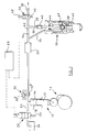
- the fuel system illustrated in Figure 1 comprises a pump 10 which includes a pumping plunger 12 reciprocable within a bore 14 under the influence of a cam arrangement 16.
- the plunger 12 and bore 14 together define a pumping chamber 18.
- the pumping chamber 18 communicates through a passage 20 within an electromagnetically actuable spill valve 22, the spill valve 22 including a port which communicates with a low pressure fuel reservoir 24.
- the spill valve 22 is illustrated diagrammatically and comprises a valve member slidable within a bore and biased by a spring 26 towards a position in which communication is permitted between the low pressure reservoir 24 and the pumping chamber 18.
- the valve member of the spill valve 22 is moveable under the influence of an electromagnetic actuator against the action of the spring 26 to a position in which such communication is broken.
- the supply of an electric current to the actuator of the spill valve 22 is controlled by means of an electronic controller 28.
- the pumping chamber 18 further communicates through a delivery valve arrangement 30 with a volume or accumulator 32.
- the delivery valve arrangement 30 is illustrated as comprising a pair of non-return valves 30 a , 30 b arranged in parallel, the non-return valve 30 a being arranged to permit fuel to flow from the pumping chamber 18 to the volume 32, but prevent fuel flow in the reverse direction, and the non-return valve 30 b permitting fuel to return from the volume 32, but preventing fuel from flowing from the pumping chamber 18 to the volume 32.
- the non-return valves 30 a , 30 b are conveniently biased closed by means of springs, the rates and pre-stressing of the springs being selected depending upon the application. It will be appreciated, however that the delivery valve 30 may be of an alternative type to that illustrated diagrammatically in Figure 1.
- the volume 32 communicates through a supply passage 34 with a fuel injector 36.
- the fuel injector 36 comprises a valve needle 38 slidable within a bore formed in a nozzle body 40.
- the valve needle 38 is shaped to define one or more thrust surfaces orientated such that the application of fuel under high pressure thereto applies a force to the needle 38 urging the needle 38 away from a seating to permit fuel delivery from the supply passage 34 through the injector to one or more small outlet openings provided in the nozzle body 40.
- the valve needle 38 is biased into engagement with its seating by means of a helical compression spring 42, and in order for injection to commence, the force applied to the needle 38 by the action of fuel under pressure upon the thrust surfaces must be sufficient to overcome the action of the spring 42.
- a rod 44 is associated with the needle 38 such that movement of the needle 38 results in corresponding movement of the rod 44.
- the rod 44 engages a piston member 46 which is slidable within a cylinder 48.
- the piston member 46 and cylinder 48 together define a control chamber 50 which communicates through a passage 52 with the volume 32.
- the passage 52 includes a restriction 54, thus the rate at which fuel can flow to the control chamber 50 from the volume 32 is restricted.
- the control chamber 50 further communicates with a port of an injection control valve 56 which includes a second port communicating with a passage 58 which communicates with the low pressure fuel reservoir 24.
- the injection control valve 56 comprises a valve member which is biased by means of a spring 60 towards a position in which the control chamber 50 communicates with the low pressure reservoir.
- An electromagnetic actuator 62 is provided to move the valve member against the action of the spring 60 to a position in which such communication is broken.
- the current flowing through the actuator 62 is controlled by means of the electronic controller 28.
- the plunger 12 In use, in the position illustrated in Figure 1, the plunger 12 is about to commence inward movement under the action of the cam arrangement 16, the pumping chamber 18 being charged to a relatively low pressure with fuel from the low pressure fuel reservoir 24. As the spill valve 22 occupies its de-energized position, inward movement of the plunger 12 displaces fuel from the pumping chamber 18 to the low pressure fuel reservoir 24 without significantly pressurising the fuel in the fuel system.
- the controller 28 When it is determined that pressurization of fuel should commence, the controller 28 energises the actuator of the spill valve 22, moving the spill valve 22 to its alternative position. Such movement of the spill valve 22 breaks the communication between the pumping chamber 18 and the low pressure reservoir 24. As fuel is no longer permitted to escape to the low pressure drain reservoir 24 through the spill valve 22, continued inward movement of the plunger 12 pressurises the fuel within the pumping chamber 18, the passages in communication with the pumping chamber 18 and the volume 32.
- the injection control valve 56 is de-energized, and occupies a position in which the control chamber 50 communicates with the low pressure drain reservoir. As a result, the fuel pressure applied to the piston member 46 is low, the restriction 54 limiting the supply of fuel to the control chamber 50. Whilst the injection control valve 56 remains in this position, continued inward movement of the plunger 12 continues to pressurize the fuel within the fuel supply system, thus the fuel pressure applied to the thrust surfaces of the needle 38 increases. Once the fuel pressure exceeds a predetermined level, the needle 38 is able to lift against the action of the spring 42, thus fuel injection commences.
- the injection control valve 56 is energized, the communication between the control chamber 50 and low pressure reservoir is broken, and the continued flow of fuel at a restricted rate through the restrictor 54 increases the fuel pressure within the control chamber 50.
- the fuel pressure within the control chamber 50 rises to a sufficient extent that the force applied to the needle 38 by the spring 42 together with the force resulting from the application of fuel under pressure to the control chamber 50 is sufficient to cause the needle 38 to return into engagement with its seating, thus terminating injection.
- the injection control valve 56 is de-energized. The fuel pressure within the control chamber 50 is thereby relieved, and the valve needle 38 is able to lift away from its seating under the action of the fuel pressure upon the thrust surfaces of the needle 38.
- Termination of injection is achieved by de-energizing the actuator of the spill valve 22, the spring 26 returning the spill valve 22 to the position shown. Once this position has been reached, fuel is able to escape from the volume 32 through the non-return valve 30 b of the delivery valve arrangement 30 to the low pressure fuel reservoir 24. It will therefore be appreciated that the fuel pressure applied to the thrust surfaces of the needle 38 is rapidly relieved, and the needle 38 returns into engagement with its seating under the action of the spring 42, thus terminating injection. Continued inward movement of the plunger 12 displaces further fuel from the pumping chamber 18 through the spill valve 22 to the low pressure reservoir 24.
- the plunger 12 will reach its innermost position, and thereafter will be withdrawn from the bore 14 under the action of, for example, a return spring (not shown).
- a return spring (not shown).
- Such outward movement of the plunger 12 draws fuel into the pumping chamber 18 from the low pressure reservoir 24, thus charging the pumping chamber 18 with fuel at relatively low pressure ready for commencement of the next pumping and injection cycle.
- the mode of operation of the fuel system may be modified if desired, for example when the engine is operating at low speed, such that prior to switching of the spill valve 22 to commence pressurization of fuel within the pumping chamber 18, the injection control valve 56 is switched to its alternative position by energization of the actuator 62 thereof. Subsequent switching of the spill valve 22 commences pressurization of fuel.
- the actuator 62 associated with the injection control valve 56 is de-energized, the injection control valve 56 moving under the action of the spring 60 to a position in which the fuel pressure within the control chamber 50 is relieved to the low pressure fuel reservoir 24.
- the presence of the restriction 54 restricts the rate at which fuel can flow towards the control chamber 50 to a relatively low level.
- Injection of fuel may be temporarily interrupted by re-energizing the actuator 62 associated with the injection control valve 56, and subsequently de-energizing the actuator 62. Termination of injection is controlled by de-energization of the spill valve 22 as described hereinbefore.
- the actuation of the injection control valve 56 is described as splitting an injection into two parts, for example a pilot injection followed by a main injection, it will be appreciated that during each injection cycle, the injection control valve 56 may be actuated twice, or more times, thus splitting each injection into three or more parts.
- Figure 2 illustrates a modification to the arrangement of Figure 1.
- the restriction 54 is omitted, and instead the injection control valve 56 is located within the passage 52 between the volume 32 and the control chamber 50.
- a restriction 64 is provided to limit the rate at which fuel is able to escape from the control chamber 50 to the low pressure reservoir, in use.
- the injection control valve 56 of this arrangement is orientated such that when the actuator 62 thereof is de-energized, the spring 60 urges the valve member of the injection control valve 56 to a position in which communication between the volume 32 and control chamber 50 is not permitted. In this position, the control chamber 50 communicates through the restriction 64 with the low pressure reservoir, thus the fuel pressure applied to the piston 46 is relatively low.
- pressurization of the fuel within the volume 32 by the operation of the pump 10 will, once the pressure rises above a predetermined pressure, lift the needle 38 away from its seating against the action of the spring 42.
- Energization of the actuator 62 of the injection control valve 56 permits fuel to flow to the control chamber 50, thus increasing the magnitude of the force urging the needle 38 towards its seating, and it will be appreciated that a point will be reached beyond which the needle 38 moves to engage its seating, thus terminating injection.
- a small quantity of fuel escapes through the restriction 64 to the low pressure drain reservoir.
- the actuator 62 is de-energized, and the spring 60 returns the injection control valve 56 to the position illustrated, and as a result the fuel pressure within the control chamber 50 falls to a level sufficient to allow the needle to lift away from its seating, thus injection recommences.
- termination of the injection cycle is controlled by de-energizing the actuator associated with the spill valve 22 to permit the fuel pressure within the volume 32 to drop to a level insufficient to allow the needle 38 to move against the action of the spring 42.
- the arrangement of Figure 2 may be modified by omitting the flow path containing the restriction 64, and instead permitting fuel to escape from the control chamber 50 at a restricted rate between the piston member 46 and the cylinder 48.
- Figure 3 illustrates a further alternative arrangement, the arrangement of Figure 3 being similar to that of Figure 2 but in which the injection control valve 56 takes the form of a three-way valve, the injection control valve 56 controlling whether the control chamber 50 communicates with a low pressure drain or alternatively with the fuel pressure present within the volume 32.
- the injection control valve 56 is biased by means of the spring 60 towards its position in which the control chamber communicates with the low pressure drain, the injection control valve 56 being moveable against the action of the spring 60 by means of an electromagnetic actuator 62, energization of which is controlled by the electronic controller 28 as described hereinbefore with reference to Figure 1.
- a restriction 64 is provided in the arrangement of Figure 3 between the injection control valve 56 and the low pressure reservoir, the provision of the restriction 64 is optional.
- the provision of the restriction 64 restricts the rate of movement of the needle 38 away from its seating which may have a beneficial effect upon the performance of the engine with which the fuel system is used.
- a separate snubber valve may be fitted above the piston 46 to limit the rate of movement of the needle 38.
- Each fuel system described hereinbefore may take the form of a pump injector arrangement in which the fuel pump 10 and injector 36 are integral with one another or rigidly secured to one another, or alternatively the fuel pump 10 and injector 36 may be physically separated from one another, fuel being supplied from the pump 10 to the injector 36 through an appropriate high pressure fuel pipe.
- the pump 10 may incorporate a mechanically controlled spill arrangement in which, for example, fuel is able to escape from the pumping chamber 18 to the low pressure reservoir 24 once a port which communicates with the bore 14 registers with a groove or passage formed in the plunger 12.
- the pump 10 may be replaced by a rotary fuel pump and an appropriate distributor used to distribute the pressurised fuel to a series of injectors, in turn, through appropriate high pressure fuel pipes, each injector being fitted with an injection control valve of the type described hereinbefore.
Landscapes
- Engineering & Computer Science (AREA)
- Chemical & Material Sciences (AREA)
- Combustion & Propulsion (AREA)
- Mechanical Engineering (AREA)
- General Engineering & Computer Science (AREA)
- Physics & Mathematics (AREA)
- Fluid Mechanics (AREA)
- Fuel-Injection Apparatus (AREA)
Abstract
Description
Claims (10)
- A fuel system comprising a fuel pump (10) having a pumping chamber (18), a spill valve (22) operable to control the timing of fuel pressurization by the pump (10), a fuel injector (36) comprising a valve needle (38) slidable within a bore, a surface associated with the valve needle (38) being exposed to the fuel pressure within a control chamber (50), and an injection control valve (56) arranged to control the fuel pressure within the control chamber (50), characterised in that the injection control valve (56) comprises an electromagnetically actuable valve arranged such that when the actuator (62) is energized, the control chamber (50) is exposed to substantially the fuel pressure within the pumping chamber (18) of the fuel pump (10), de-energization of the actuator (62) of the injection control valve (56) permitting the fuel pressure within the control chamber (50) to fall to a level sufficiently low to allow injection of fuel to occur through the fuel injector (36).
- The fuel injector as claimed in Claim 1, whereby the pumping chamber (18) communicates with an accumulator (32) for fuel.
- The fuel system as claimed in Claim 1 or 2, wherein the fuel injector (36) comprises a piston member (46) which is movable with the valve needle (38), a surface of the piston member (46) being exposed to fuel pressure within the control chamber (50).
- The fuel system as claimed in any of Claims 1 to 3, further comprising a restriction (54) for restricting the rate of flow of fuel into the control chamber (50).
- The fuel system as claimed in Claim 4, wherein the restriction (54) is located in a flow passage which provides communication between the accumulator (32) and the control chamber (50).
- The fuel system as claimed in any of Claims 1 to 3, further comprising means (64) for restricting the rate at which fuel is able to escape from the control chamber (50).
- The fuel system as claimed in Claim 6, comprising a flow passage communicating with the control chamber (50), the flow passage being provided with a restriction (64) for restricting the rate at which fuel is able to escape from the control chamber (50).
- The fuel system as claimed in Claim 6, comprising a snubber valve for restricting the rate at which fuel is able to escape from the control chamber (50).
- The fuel system as claimed in any of Claims 1 to 8, wherein the injection control valve (56) takes the form of a three-way valve for controlling communication between the control chamber (50) and a low pressure drain and between the control chamber (50) and the accumulator (32).
- The fuel system as claimed in any of Claims 1 to 9, wherein the fuel injector (36) and the pump (10) are integrally formed.
Applications Claiming Priority (2)
| Application Number | Priority Date | Filing Date | Title |
|---|---|---|---|
| GB9821929 | 1998-10-09 | ||
| GBGB9821929.8A GB9821929D0 (en) | 1998-10-09 | 1998-10-09 | Fuel system |
Publications (2)
| Publication Number | Publication Date |
|---|---|
| EP0992675A2 true EP0992675A2 (en) | 2000-04-12 |
| EP0992675A3 EP0992675A3 (en) | 2000-10-11 |
Family
ID=10840193
Family Applications (1)
| Application Number | Title | Priority Date | Filing Date |
|---|---|---|---|
| EP99307975A Withdrawn EP0992675A3 (en) | 1998-10-09 | 1999-10-08 | Fuel system |
Country Status (2)
| Country | Link |
|---|---|
| EP (1) | EP0992675A3 (en) |
| GB (1) | GB9821929D0 (en) |
Cited By (6)
| Publication number | Priority date | Publication date | Assignee | Title |
|---|---|---|---|---|
| WO2002004805A1 (en) | 2000-07-10 | 2002-01-17 | Mitsubishi Heavy Industries, Ltd. | Fuel injection device |
| WO2003016705A1 (en) * | 2001-08-17 | 2003-02-27 | Volvo Teknisk Utveckling Ab | Method of controlling the injection of fuel into a combustion chamber and a fuel injection device for performing said method |
| WO2004005702A1 (en) * | 2002-07-04 | 2004-01-15 | Delphi Technologies, Inc. | Control valve arrangement |
| WO2004007934A1 (en) * | 2002-07-13 | 2004-01-22 | Delphi Technologies, Inc. | Control method |
| EP1316718A3 (en) * | 2001-11-30 | 2004-04-28 | Robert Bosch Gmbh | Fuel injection system for internal combustion engine |
| WO2005124144A1 (en) * | 2004-06-04 | 2005-12-29 | Renault Trucks | Pump injector |
Family Cites Families (3)
| Publication number | Priority date | Publication date | Assignee | Title |
|---|---|---|---|---|
| GB2289313B (en) * | 1994-05-13 | 1998-09-30 | Caterpillar Inc | Fluid injector system |
| US5687693A (en) * | 1994-07-29 | 1997-11-18 | Caterpillar Inc. | Hydraulically-actuated fuel injector with direct control needle valve |
| GB9820237D0 (en) * | 1998-09-18 | 1998-11-11 | Lucas Ind Plc | Fuel injector |
-
1998
- 1998-10-09 GB GBGB9821929.8A patent/GB9821929D0/en not_active Ceased
-
1999
- 1999-10-08 EP EP99307975A patent/EP0992675A3/en not_active Withdrawn
Cited By (11)
| Publication number | Priority date | Publication date | Assignee | Title |
|---|---|---|---|---|
| WO2002004805A1 (en) | 2000-07-10 | 2002-01-17 | Mitsubishi Heavy Industries, Ltd. | Fuel injection device |
| EP1302656A4 (en) * | 2000-07-10 | 2009-05-13 | Mitsubishi Heavy Ind Ltd | Fuel injection device |
| WO2003016705A1 (en) * | 2001-08-17 | 2003-02-27 | Volvo Teknisk Utveckling Ab | Method of controlling the injection of fuel into a combustion chamber and a fuel injection device for performing said method |
| US6978769B2 (en) | 2001-08-17 | 2005-12-27 | Volvo Technology Ab | Method of controlling the injection of fuel into a combustion chamber and a fuel injection device for performing said method |
| EP1947323A3 (en) * | 2001-08-17 | 2008-12-17 | Volvo Technology Corporation | Method of controlling the injection of fuel into a combustion chamber and a fuel injection device for performing said method |
| EP1316718A3 (en) * | 2001-11-30 | 2004-04-28 | Robert Bosch Gmbh | Fuel injection system for internal combustion engine |
| US6796290B2 (en) | 2001-11-30 | 2004-09-28 | Robert Bosch Gmbh | Fuel injection system for an internal combustion engine |
| WO2004005702A1 (en) * | 2002-07-04 | 2004-01-15 | Delphi Technologies, Inc. | Control valve arrangement |
| US7874502B2 (en) | 2002-07-04 | 2011-01-25 | Delphi Technologies Holding S.Arl | Control valve arrangement |
| WO2004007934A1 (en) * | 2002-07-13 | 2004-01-22 | Delphi Technologies, Inc. | Control method |
| WO2005124144A1 (en) * | 2004-06-04 | 2005-12-29 | Renault Trucks | Pump injector |
Also Published As
| Publication number | Publication date |
|---|---|
| EP0992675A3 (en) | 2000-10-11 |
| GB9821929D0 (en) | 1998-12-02 |
Similar Documents
| Publication | Publication Date | Title |
|---|---|---|
| EP0823550B1 (en) | Injector | |
| EP0889230B1 (en) | Fuel injector | |
| US5771865A (en) | Fuel injection system of an engine and a control method therefor | |
| US5551398A (en) | Electronically-controlled fluid injector system having pre-injection pressurizable fluid storage chamber and direct-operated check | |
| US4777921A (en) | Fuel injection system | |
| US6843053B2 (en) | Fuel system | |
| US6167869B1 (en) | Fuel injector utilizing a multiple current level solenoid | |
| KR20010043493A (en) | Fuel injection system | |
| GB2201753A (en) | Piezoelectric fuel injection control valve | |
| US6651625B1 (en) | Fuel system and pump suitable for use therein | |
| US6405940B2 (en) | Fuel injector | |
| US6260768B1 (en) | Pump injector including valve needle and spill valve | |
| KR100715639B1 (en) | Fuel injection device | |
| EP2241744A1 (en) | Common Rail Fuel Pump and Control Method for a Common Rail Fuel Pump | |
| EP1098087B1 (en) | Fuel Injector | |
| CN1873213B (en) | Fuel injector control system and method | |
| EP0992675A2 (en) | Fuel system | |
| US6935580B2 (en) | Valve assembly having multiple rate shaping capabilities and fuel injector using same | |
| EP0844384B1 (en) | Injector | |
| EP0974750B1 (en) | Fuel-injection pump having a vapor-prevention accumulator | |
| JP2004515708A (en) | Fuel injection device for internal combustion engines | |
| JP4196519B2 (en) | High pressure fuel supply device for internal combustion engine | |
| EP1065368A2 (en) | Fuel injector | |
| GB2320289A (en) | Directly controlled unit fuel injector for i.c. engine | |
| EP0055117B1 (en) | Fuel injection pump |
Legal Events
| Date | Code | Title | Description |
|---|---|---|---|
| PUAI | Public reference made under article 153(3) epc to a published international application that has entered the european phase |
Free format text: ORIGINAL CODE: 0009012 |
|
| AK | Designated contracting states |
Kind code of ref document: A2 Designated state(s): AT BE CH CY DE DK ES FI FR GB GR IE IT LI LU MC NL PT SE |
|
| AX | Request for extension of the european patent |
Free format text: AL;LT;LV;MK;RO;SI |
|
| PUAL | Search report despatched |
Free format text: ORIGINAL CODE: 0009013 |
|
| AK | Designated contracting states |
Kind code of ref document: A3 Designated state(s): AT BE CH CY DE DK ES FI FR GB GR IE IT LI LU MC NL PT SE |
|
| AX | Request for extension of the european patent |
Free format text: AL;LT;LV;MK;RO;SI |
|
| RAP1 | Party data changed (applicant data changed or rights of an application transferred) |
Owner name: DELPHI TECHNOLOGIES, INC. |
|
| AKX | Designation fees paid | ||
| REG | Reference to a national code |
Ref country code: DE Ref legal event code: 8566 |
|
| STAA | Information on the status of an ep patent application or granted ep patent |
Free format text: STATUS: THE APPLICATION IS DEEMED TO BE WITHDRAWN |
|
| 18D | Application deemed to be withdrawn |
Effective date: 20010412 |