EP0992431A1 - Method of producing sealed packages containing pourable food products from a tube of packing material, and packing unit implementing such a method - Google Patents
Method of producing sealed packages containing pourable food products from a tube of packing material, and packing unit implementing such a method Download PDFInfo
- Publication number
- EP0992431A1 EP0992431A1 EP98830588A EP98830588A EP0992431A1 EP 0992431 A1 EP0992431 A1 EP 0992431A1 EP 98830588 A EP98830588 A EP 98830588A EP 98830588 A EP98830588 A EP 98830588A EP 0992431 A1 EP0992431 A1 EP 0992431A1
- Authority
- EP
- European Patent Office
- Prior art keywords
- tube
- jaws
- packing material
- parting line
- unit
- Prior art date
- Legal status (The legal status is an assumption and is not a legal conclusion. Google has not performed a legal analysis and makes no representation as to the accuracy of the status listed.)
- Granted
Links
Images



Classifications
-
- B—PERFORMING OPERATIONS; TRANSPORTING
- B65—CONVEYING; PACKING; STORING; HANDLING THIN OR FILAMENTARY MATERIAL
- B65B—MACHINES, APPARATUS OR DEVICES FOR, OR METHODS OF, PACKAGING ARTICLES OR MATERIALS; UNPACKING
- B65B9/00—Enclosing successive articles, or quantities of material, e.g. liquids or semiliquids, in flat, folded, or tubular webs of flexible sheet material; Subdividing filled flexible tubes to form packages
- B65B9/10—Enclosing successive articles, or quantities of material, in preformed tubular webs, or in webs formed into tubes around filling nozzles, e.g. extruded tubular webs
- B65B9/20—Enclosing successive articles, or quantities of material, in preformed tubular webs, or in webs formed into tubes around filling nozzles, e.g. extruded tubular webs the webs being formed into tubes in situ around the filling nozzles
- B65B9/207—Enclosing successive articles, or quantities of material, in preformed tubular webs, or in webs formed into tubes around filling nozzles, e.g. extruded tubular webs the webs being formed into tubes in situ around the filling nozzles the web advancing continuously
-
- B—PERFORMING OPERATIONS; TRANSPORTING
- B29—WORKING OF PLASTICS; WORKING OF SUBSTANCES IN A PLASTIC STATE IN GENERAL
- B29C—SHAPING OR JOINING OF PLASTICS; SHAPING OF MATERIAL IN A PLASTIC STATE, NOT OTHERWISE PROVIDED FOR; AFTER-TREATMENT OF THE SHAPED PRODUCTS, e.g. REPAIRING
- B29C66/00—General aspects of processes or apparatus for joining preformed parts
- B29C66/70—General aspects of processes or apparatus for joining preformed parts characterised by the composition, physical properties or the structure of the material of the parts to be joined; Joining with non-plastics material
- B29C66/72—General aspects of processes or apparatus for joining preformed parts characterised by the composition, physical properties or the structure of the material of the parts to be joined; Joining with non-plastics material characterised by the structure of the material of the parts to be joined
- B29C66/723—General aspects of processes or apparatus for joining preformed parts characterised by the composition, physical properties or the structure of the material of the parts to be joined; Joining with non-plastics material characterised by the structure of the material of the parts to be joined being multi-layered
- B29C66/7232—General aspects of processes or apparatus for joining preformed parts characterised by the composition, physical properties or the structure of the material of the parts to be joined; Joining with non-plastics material characterised by the structure of the material of the parts to be joined being multi-layered comprising a non-plastics layer
- B29C66/72321—General aspects of processes or apparatus for joining preformed parts characterised by the composition, physical properties or the structure of the material of the parts to be joined; Joining with non-plastics material characterised by the structure of the material of the parts to be joined being multi-layered comprising a non-plastics layer consisting of metals or their alloys
-
- B—PERFORMING OPERATIONS; TRANSPORTING
- B29—WORKING OF PLASTICS; WORKING OF SUBSTANCES IN A PLASTIC STATE IN GENERAL
- B29C—SHAPING OR JOINING OF PLASTICS; SHAPING OF MATERIAL IN A PLASTIC STATE, NOT OTHERWISE PROVIDED FOR; AFTER-TREATMENT OF THE SHAPED PRODUCTS, e.g. REPAIRING
- B29C65/00—Joining or sealing of preformed parts, e.g. welding of plastics materials; Apparatus therefor
- B29C65/02—Joining or sealing of preformed parts, e.g. welding of plastics materials; Apparatus therefor by heating, with or without pressure
- B29C65/34—Joining or sealing of preformed parts, e.g. welding of plastics materials; Apparatus therefor by heating, with or without pressure using heated elements which remain in the joint, e.g. "verlorenes Schweisselement"
- B29C65/36—Joining or sealing of preformed parts, e.g. welding of plastics materials; Apparatus therefor by heating, with or without pressure using heated elements which remain in the joint, e.g. "verlorenes Schweisselement" heated by induction
- B29C65/3604—Joining or sealing of preformed parts, e.g. welding of plastics materials; Apparatus therefor by heating, with or without pressure using heated elements which remain in the joint, e.g. "verlorenes Schweisselement" heated by induction characterised by the type of elements heated by induction which remain in the joint
- B29C65/3656—Joining or sealing of preformed parts, e.g. welding of plastics materials; Apparatus therefor by heating, with or without pressure using heated elements which remain in the joint, e.g. "verlorenes Schweisselement" heated by induction characterised by the type of elements heated by induction which remain in the joint being a layer of a multilayer part to be joined, e.g. for joining plastic-metal laminates
-
- B—PERFORMING OPERATIONS; TRANSPORTING
- B29—WORKING OF PLASTICS; WORKING OF SUBSTANCES IN A PLASTIC STATE IN GENERAL
- B29C—SHAPING OR JOINING OF PLASTICS; SHAPING OF MATERIAL IN A PLASTIC STATE, NOT OTHERWISE PROVIDED FOR; AFTER-TREATMENT OF THE SHAPED PRODUCTS, e.g. REPAIRING
- B29C65/00—Joining or sealing of preformed parts, e.g. welding of plastics materials; Apparatus therefor
- B29C65/02—Joining or sealing of preformed parts, e.g. welding of plastics materials; Apparatus therefor by heating, with or without pressure
- B29C65/34—Joining or sealing of preformed parts, e.g. welding of plastics materials; Apparatus therefor by heating, with or without pressure using heated elements which remain in the joint, e.g. "verlorenes Schweisselement"
- B29C65/36—Joining or sealing of preformed parts, e.g. welding of plastics materials; Apparatus therefor by heating, with or without pressure using heated elements which remain in the joint, e.g. "verlorenes Schweisselement" heated by induction
- B29C65/3668—Joining or sealing of preformed parts, e.g. welding of plastics materials; Apparatus therefor by heating, with or without pressure using heated elements which remain in the joint, e.g. "verlorenes Schweisselement" heated by induction characterised by the means for supplying heat to said heated elements which remain in the join, e.g. special induction coils
-
- B—PERFORMING OPERATIONS; TRANSPORTING
- B29—WORKING OF PLASTICS; WORKING OF SUBSTANCES IN A PLASTIC STATE IN GENERAL
- B29C—SHAPING OR JOINING OF PLASTICS; SHAPING OF MATERIAL IN A PLASTIC STATE, NOT OTHERWISE PROVIDED FOR; AFTER-TREATMENT OF THE SHAPED PRODUCTS, e.g. REPAIRING
- B29C65/00—Joining or sealing of preformed parts, e.g. welding of plastics materials; Apparatus therefor
- B29C65/02—Joining or sealing of preformed parts, e.g. welding of plastics materials; Apparatus therefor by heating, with or without pressure
- B29C65/34—Joining or sealing of preformed parts, e.g. welding of plastics materials; Apparatus therefor by heating, with or without pressure using heated elements which remain in the joint, e.g. "verlorenes Schweisselement"
- B29C65/36—Joining or sealing of preformed parts, e.g. welding of plastics materials; Apparatus therefor by heating, with or without pressure using heated elements which remain in the joint, e.g. "verlorenes Schweisselement" heated by induction
- B29C65/3672—Joining or sealing of preformed parts, e.g. welding of plastics materials; Apparatus therefor by heating, with or without pressure using heated elements which remain in the joint, e.g. "verlorenes Schweisselement" heated by induction characterised by the composition of the elements heated by induction which remain in the joint
- B29C65/3676—Joining or sealing of preformed parts, e.g. welding of plastics materials; Apparatus therefor by heating, with or without pressure using heated elements which remain in the joint, e.g. "verlorenes Schweisselement" heated by induction characterised by the composition of the elements heated by induction which remain in the joint being metallic
- B29C65/368—Joining or sealing of preformed parts, e.g. welding of plastics materials; Apparatus therefor by heating, with or without pressure using heated elements which remain in the joint, e.g. "verlorenes Schweisselement" heated by induction characterised by the composition of the elements heated by induction which remain in the joint being metallic with a polymer coating
-
- B—PERFORMING OPERATIONS; TRANSPORTING
- B29—WORKING OF PLASTICS; WORKING OF SUBSTANCES IN A PLASTIC STATE IN GENERAL
- B29C—SHAPING OR JOINING OF PLASTICS; SHAPING OF MATERIAL IN A PLASTIC STATE, NOT OTHERWISE PROVIDED FOR; AFTER-TREATMENT OF THE SHAPED PRODUCTS, e.g. REPAIRING
- B29C65/00—Joining or sealing of preformed parts, e.g. welding of plastics materials; Apparatus therefor
- B29C65/74—Joining or sealing of preformed parts, e.g. welding of plastics materials; Apparatus therefor by welding and severing, or by joining and severing, the severing being performed in the area to be joined, next to the area to be joined, in the joint area or next to the joint area
- B29C65/745—Joining or sealing of preformed parts, e.g. welding of plastics materials; Apparatus therefor by welding and severing, or by joining and severing, the severing being performed in the area to be joined, next to the area to be joined, in the joint area or next to the joint area using a single unit having both a severing tool and a welding tool
- B29C65/7451—Joining or sealing of preformed parts, e.g. welding of plastics materials; Apparatus therefor by welding and severing, or by joining and severing, the severing being performed in the area to be joined, next to the area to be joined, in the joint area or next to the joint area using a single unit having both a severing tool and a welding tool the severing tool and the welding tool being movable with respect to one-another
-
- B—PERFORMING OPERATIONS; TRANSPORTING
- B29—WORKING OF PLASTICS; WORKING OF SUBSTANCES IN A PLASTIC STATE IN GENERAL
- B29C—SHAPING OR JOINING OF PLASTICS; SHAPING OF MATERIAL IN A PLASTIC STATE, NOT OTHERWISE PROVIDED FOR; AFTER-TREATMENT OF THE SHAPED PRODUCTS, e.g. REPAIRING
- B29C66/00—General aspects of processes or apparatus for joining preformed parts
- B29C66/01—General aspects dealing with the joint area or with the area to be joined
- B29C66/05—Particular design of joint configurations
- B29C66/10—Particular design of joint configurations particular design of the joint cross-sections
- B29C66/11—Joint cross-sections comprising a single joint-segment, i.e. one of the parts to be joined comprising a single joint-segment in the joint cross-section
- B29C66/112—Single lapped joints
- B29C66/1122—Single lap to lap joints, i.e. overlap joints
-
- B—PERFORMING OPERATIONS; TRANSPORTING
- B29—WORKING OF PLASTICS; WORKING OF SUBSTANCES IN A PLASTIC STATE IN GENERAL
- B29C—SHAPING OR JOINING OF PLASTICS; SHAPING OF MATERIAL IN A PLASTIC STATE, NOT OTHERWISE PROVIDED FOR; AFTER-TREATMENT OF THE SHAPED PRODUCTS, e.g. REPAIRING
- B29C66/00—General aspects of processes or apparatus for joining preformed parts
- B29C66/40—General aspects of joining substantially flat articles, e.g. plates, sheets or web-like materials; Making flat seams in tubular or hollow articles; Joining single elements to substantially flat surfaces
- B29C66/41—Joining substantially flat articles ; Making flat seams in tubular or hollow articles
- B29C66/43—Joining a relatively small portion of the surface of said articles
- B29C66/431—Joining the articles to themselves
- B29C66/4312—Joining the articles to themselves for making flat seams in tubular or hollow articles, e.g. transversal seams
-
- B—PERFORMING OPERATIONS; TRANSPORTING
- B29—WORKING OF PLASTICS; WORKING OF SUBSTANCES IN A PLASTIC STATE IN GENERAL
- B29C—SHAPING OR JOINING OF PLASTICS; SHAPING OF MATERIAL IN A PLASTIC STATE, NOT OTHERWISE PROVIDED FOR; AFTER-TREATMENT OF THE SHAPED PRODUCTS, e.g. REPAIRING
- B29C66/00—General aspects of processes or apparatus for joining preformed parts
- B29C66/70—General aspects of processes or apparatus for joining preformed parts characterised by the composition, physical properties or the structure of the material of the parts to be joined; Joining with non-plastics material
- B29C66/72—General aspects of processes or apparatus for joining preformed parts characterised by the composition, physical properties or the structure of the material of the parts to be joined; Joining with non-plastics material characterised by the structure of the material of the parts to be joined
- B29C66/723—General aspects of processes or apparatus for joining preformed parts characterised by the composition, physical properties or the structure of the material of the parts to be joined; Joining with non-plastics material characterised by the structure of the material of the parts to be joined being multi-layered
- B29C66/7232—General aspects of processes or apparatus for joining preformed parts characterised by the composition, physical properties or the structure of the material of the parts to be joined; Joining with non-plastics material characterised by the structure of the material of the parts to be joined being multi-layered comprising a non-plastics layer
- B29C66/72327—General aspects of processes or apparatus for joining preformed parts characterised by the composition, physical properties or the structure of the material of the parts to be joined; Joining with non-plastics material characterised by the structure of the material of the parts to be joined being multi-layered comprising a non-plastics layer consisting of natural products or their composites, not provided for in B29C66/72321 - B29C66/72324
- B29C66/72328—Paper
-
- B—PERFORMING OPERATIONS; TRANSPORTING
- B29—WORKING OF PLASTICS; WORKING OF SUBSTANCES IN A PLASTIC STATE IN GENERAL
- B29C—SHAPING OR JOINING OF PLASTICS; SHAPING OF MATERIAL IN A PLASTIC STATE, NOT OTHERWISE PROVIDED FOR; AFTER-TREATMENT OF THE SHAPED PRODUCTS, e.g. REPAIRING
- B29C66/00—General aspects of processes or apparatus for joining preformed parts
- B29C66/70—General aspects of processes or apparatus for joining preformed parts characterised by the composition, physical properties or the structure of the material of the parts to be joined; Joining with non-plastics material
- B29C66/72—General aspects of processes or apparatus for joining preformed parts characterised by the composition, physical properties or the structure of the material of the parts to be joined; Joining with non-plastics material characterised by the structure of the material of the parts to be joined
- B29C66/723—General aspects of processes or apparatus for joining preformed parts characterised by the composition, physical properties or the structure of the material of the parts to be joined; Joining with non-plastics material characterised by the structure of the material of the parts to be joined being multi-layered
- B29C66/7234—General aspects of processes or apparatus for joining preformed parts characterised by the composition, physical properties or the structure of the material of the parts to be joined; Joining with non-plastics material characterised by the structure of the material of the parts to be joined being multi-layered comprising a barrier layer
-
- B—PERFORMING OPERATIONS; TRANSPORTING
- B29—WORKING OF PLASTICS; WORKING OF SUBSTANCES IN A PLASTIC STATE IN GENERAL
- B29C—SHAPING OR JOINING OF PLASTICS; SHAPING OF MATERIAL IN A PLASTIC STATE, NOT OTHERWISE PROVIDED FOR; AFTER-TREATMENT OF THE SHAPED PRODUCTS, e.g. REPAIRING
- B29C66/00—General aspects of processes or apparatus for joining preformed parts
- B29C66/70—General aspects of processes or apparatus for joining preformed parts characterised by the composition, physical properties or the structure of the material of the parts to be joined; Joining with non-plastics material
- B29C66/73—General aspects of processes or apparatus for joining preformed parts characterised by the composition, physical properties or the structure of the material of the parts to be joined; Joining with non-plastics material characterised by the intensive physical properties of the material of the parts to be joined, by the optical properties of the material of the parts to be joined, by the extensive physical properties of the parts to be joined, by the state of the material of the parts to be joined or by the material of the parts to be joined being a thermoplastic or a thermoset
- B29C66/739—General aspects of processes or apparatus for joining preformed parts characterised by the composition, physical properties or the structure of the material of the parts to be joined; Joining with non-plastics material characterised by the intensive physical properties of the material of the parts to be joined, by the optical properties of the material of the parts to be joined, by the extensive physical properties of the parts to be joined, by the state of the material of the parts to be joined or by the material of the parts to be joined being a thermoplastic or a thermoset characterised by the material of the parts to be joined being a thermoplastic or a thermoset
- B29C66/7392—General aspects of processes or apparatus for joining preformed parts characterised by the composition, physical properties or the structure of the material of the parts to be joined; Joining with non-plastics material characterised by the intensive physical properties of the material of the parts to be joined, by the optical properties of the material of the parts to be joined, by the extensive physical properties of the parts to be joined, by the state of the material of the parts to be joined or by the material of the parts to be joined being a thermoplastic or a thermoset characterised by the material of the parts to be joined being a thermoplastic or a thermoset characterised by the material of at least one of the parts being a thermoplastic
- B29C66/73921—General aspects of processes or apparatus for joining preformed parts characterised by the composition, physical properties or the structure of the material of the parts to be joined; Joining with non-plastics material characterised by the intensive physical properties of the material of the parts to be joined, by the optical properties of the material of the parts to be joined, by the extensive physical properties of the parts to be joined, by the state of the material of the parts to be joined or by the material of the parts to be joined being a thermoplastic or a thermoset characterised by the material of the parts to be joined being a thermoplastic or a thermoset characterised by the material of at least one of the parts being a thermoplastic characterised by the materials of both parts being thermoplastics
-
- B—PERFORMING OPERATIONS; TRANSPORTING
- B29—WORKING OF PLASTICS; WORKING OF SUBSTANCES IN A PLASTIC STATE IN GENERAL
- B29C—SHAPING OR JOINING OF PLASTICS; SHAPING OF MATERIAL IN A PLASTIC STATE, NOT OTHERWISE PROVIDED FOR; AFTER-TREATMENT OF THE SHAPED PRODUCTS, e.g. REPAIRING
- B29C66/00—General aspects of processes or apparatus for joining preformed parts
- B29C66/80—General aspects of machine operations or constructions and parts thereof
-
- B—PERFORMING OPERATIONS; TRANSPORTING
- B29—WORKING OF PLASTICS; WORKING OF SUBSTANCES IN A PLASTIC STATE IN GENERAL
- B29C—SHAPING OR JOINING OF PLASTICS; SHAPING OF MATERIAL IN A PLASTIC STATE, NOT OTHERWISE PROVIDED FOR; AFTER-TREATMENT OF THE SHAPED PRODUCTS, e.g. REPAIRING
- B29C66/00—General aspects of processes or apparatus for joining preformed parts
- B29C66/80—General aspects of machine operations or constructions and parts thereof
- B29C66/81—General aspects of the pressing elements, i.e. the elements applying pressure on the parts to be joined in the area to be joined, e.g. the welding jaws or clamps
- B29C66/814—General aspects of the pressing elements, i.e. the elements applying pressure on the parts to be joined in the area to be joined, e.g. the welding jaws or clamps characterised by the design of the pressing elements, e.g. of the welding jaws or clamps
- B29C66/8141—General aspects of the pressing elements, i.e. the elements applying pressure on the parts to be joined in the area to be joined, e.g. the welding jaws or clamps characterised by the design of the pressing elements, e.g. of the welding jaws or clamps characterised by the surface geometry of the part of the pressing elements, e.g. welding jaws or clamps, coming into contact with the parts to be joined
- B29C66/81427—General aspects of the pressing elements, i.e. the elements applying pressure on the parts to be joined in the area to be joined, e.g. the welding jaws or clamps characterised by the design of the pressing elements, e.g. of the welding jaws or clamps characterised by the surface geometry of the part of the pressing elements, e.g. welding jaws or clamps, coming into contact with the parts to be joined comprising a single ridge, e.g. for making a weakening line; comprising a single tooth
-
- B—PERFORMING OPERATIONS; TRANSPORTING
- B29—WORKING OF PLASTICS; WORKING OF SUBSTANCES IN A PLASTIC STATE IN GENERAL
- B29C—SHAPING OR JOINING OF PLASTICS; SHAPING OF MATERIAL IN A PLASTIC STATE, NOT OTHERWISE PROVIDED FOR; AFTER-TREATMENT OF THE SHAPED PRODUCTS, e.g. REPAIRING
- B29C66/00—General aspects of processes or apparatus for joining preformed parts
- B29C66/80—General aspects of machine operations or constructions and parts thereof
- B29C66/81—General aspects of the pressing elements, i.e. the elements applying pressure on the parts to be joined in the area to be joined, e.g. the welding jaws or clamps
- B29C66/814—General aspects of the pressing elements, i.e. the elements applying pressure on the parts to be joined in the area to be joined, e.g. the welding jaws or clamps characterised by the design of the pressing elements, e.g. of the welding jaws or clamps
- B29C66/8141—General aspects of the pressing elements, i.e. the elements applying pressure on the parts to be joined in the area to be joined, e.g. the welding jaws or clamps characterised by the design of the pressing elements, e.g. of the welding jaws or clamps characterised by the surface geometry of the part of the pressing elements, e.g. welding jaws or clamps, coming into contact with the parts to be joined
- B29C66/81431—General aspects of the pressing elements, i.e. the elements applying pressure on the parts to be joined in the area to be joined, e.g. the welding jaws or clamps characterised by the design of the pressing elements, e.g. of the welding jaws or clamps characterised by the surface geometry of the part of the pressing elements, e.g. welding jaws or clamps, coming into contact with the parts to be joined comprising a single cavity, e.g. a groove
-
- B—PERFORMING OPERATIONS; TRANSPORTING
- B29—WORKING OF PLASTICS; WORKING OF SUBSTANCES IN A PLASTIC STATE IN GENERAL
- B29C—SHAPING OR JOINING OF PLASTICS; SHAPING OF MATERIAL IN A PLASTIC STATE, NOT OTHERWISE PROVIDED FOR; AFTER-TREATMENT OF THE SHAPED PRODUCTS, e.g. REPAIRING
- B29C66/00—General aspects of processes or apparatus for joining preformed parts
- B29C66/80—General aspects of machine operations or constructions and parts thereof
- B29C66/82—Pressure application arrangements, e.g. transmission or actuating mechanisms for joining tools or clamps
- B29C66/822—Transmission mechanisms
- B29C66/8221—Scissor or lever mechanisms, i.e. involving a pivot point
-
- B—PERFORMING OPERATIONS; TRANSPORTING
- B29—WORKING OF PLASTICS; WORKING OF SUBSTANCES IN A PLASTIC STATE IN GENERAL
- B29C—SHAPING OR JOINING OF PLASTICS; SHAPING OF MATERIAL IN A PLASTIC STATE, NOT OTHERWISE PROVIDED FOR; AFTER-TREATMENT OF THE SHAPED PRODUCTS, e.g. REPAIRING
- B29C66/00—General aspects of processes or apparatus for joining preformed parts
- B29C66/80—General aspects of machine operations or constructions and parts thereof
- B29C66/82—Pressure application arrangements, e.g. transmission or actuating mechanisms for joining tools or clamps
- B29C66/822—Transmission mechanisms
- B29C66/8222—Pinion or rack mechanisms
-
- B—PERFORMING OPERATIONS; TRANSPORTING
- B29—WORKING OF PLASTICS; WORKING OF SUBSTANCES IN A PLASTIC STATE IN GENERAL
- B29C—SHAPING OR JOINING OF PLASTICS; SHAPING OF MATERIAL IN A PLASTIC STATE, NOT OTHERWISE PROVIDED FOR; AFTER-TREATMENT OF THE SHAPED PRODUCTS, e.g. REPAIRING
- B29C66/00—General aspects of processes or apparatus for joining preformed parts
- B29C66/80—General aspects of machine operations or constructions and parts thereof
- B29C66/82—Pressure application arrangements, e.g. transmission or actuating mechanisms for joining tools or clamps
- B29C66/822—Transmission mechanisms
- B29C66/8226—Cam mechanisms; Wedges; Eccentric mechanisms
- B29C66/82263—Follower pin or roller cooperating with a groove
-
- B—PERFORMING OPERATIONS; TRANSPORTING
- B29—WORKING OF PLASTICS; WORKING OF SUBSTANCES IN A PLASTIC STATE IN GENERAL
- B29C—SHAPING OR JOINING OF PLASTICS; SHAPING OF MATERIAL IN A PLASTIC STATE, NOT OTHERWISE PROVIDED FOR; AFTER-TREATMENT OF THE SHAPED PRODUCTS, e.g. REPAIRING
- B29C66/00—General aspects of processes or apparatus for joining preformed parts
- B29C66/80—General aspects of machine operations or constructions and parts thereof
- B29C66/83—General aspects of machine operations or constructions and parts thereof characterised by the movement of the joining or pressing tools
- B29C66/834—General aspects of machine operations or constructions and parts thereof characterised by the movement of the joining or pressing tools moving with the parts to be joined
- B29C66/8351—Jaws mounted on rollers, cylinders, drums, bands, belts or chains; Flying jaws
- B29C66/83541—Jaws mounted on rollers, cylinders, drums, bands, belts or chains; Flying jaws flying jaws, e.g. jaws mounted on crank mechanisms or following a hand over hand movement
- B29C66/83543—Jaws mounted on rollers, cylinders, drums, bands, belts or chains; Flying jaws flying jaws, e.g. jaws mounted on crank mechanisms or following a hand over hand movement cooperating flying jaws
-
- B—PERFORMING OPERATIONS; TRANSPORTING
- B29—WORKING OF PLASTICS; WORKING OF SUBSTANCES IN A PLASTIC STATE IN GENERAL
- B29C—SHAPING OR JOINING OF PLASTICS; SHAPING OF MATERIAL IN A PLASTIC STATE, NOT OTHERWISE PROVIDED FOR; AFTER-TREATMENT OF THE SHAPED PRODUCTS, e.g. REPAIRING
- B29C66/00—General aspects of processes or apparatus for joining preformed parts
- B29C66/80—General aspects of machine operations or constructions and parts thereof
- B29C66/84—Specific machine types or machines suitable for specific applications
- B29C66/849—Packaging machines
-
- B—PERFORMING OPERATIONS; TRANSPORTING
- B65—CONVEYING; PACKING; STORING; HANDLING THIN OR FILAMENTARY MATERIAL
- B65B—MACHINES, APPARATUS OR DEVICES FOR, OR METHODS OF, PACKAGING ARTICLES OR MATERIALS; UNPACKING
- B65B51/00—Devices for, or methods of, sealing or securing package folds or closures; Devices for gathering or twisting wrappers, or necks of bags
- B65B51/10—Applying or generating heat or pressure or combinations thereof
- B65B51/22—Applying or generating heat or pressure or combinations thereof by friction or ultrasonic or high-frequency electrical means
- B65B51/227—Applying or generating heat or pressure or combinations thereof by friction or ultrasonic or high-frequency electrical means by induction welding
-
- B—PERFORMING OPERATIONS; TRANSPORTING
- B65—CONVEYING; PACKING; STORING; HANDLING THIN OR FILAMENTARY MATERIAL
- B65B—MACHINES, APPARATUS OR DEVICES FOR, OR METHODS OF, PACKAGING ARTICLES OR MATERIALS; UNPACKING
- B65B51/00—Devices for, or methods of, sealing or securing package folds or closures; Devices for gathering or twisting wrappers, or necks of bags
- B65B51/10—Applying or generating heat or pressure or combinations thereof
- B65B51/26—Devices specially adapted for producing transverse or longitudinal seams in webs or tubes
- B65B51/30—Devices, e.g. jaws, for applying pressure and heat, e.g. for subdividing filled tubes
-
- B—PERFORMING OPERATIONS; TRANSPORTING
- B29—WORKING OF PLASTICS; WORKING OF SUBSTANCES IN A PLASTIC STATE IN GENERAL
- B29C—SHAPING OR JOINING OF PLASTICS; SHAPING OF MATERIAL IN A PLASTIC STATE, NOT OTHERWISE PROVIDED FOR; AFTER-TREATMENT OF THE SHAPED PRODUCTS, e.g. REPAIRING
- B29C66/00—General aspects of processes or apparatus for joining preformed parts
- B29C66/70—General aspects of processes or apparatus for joining preformed parts characterised by the composition, physical properties or the structure of the material of the parts to be joined; Joining with non-plastics material
- B29C66/71—General aspects of processes or apparatus for joining preformed parts characterised by the composition, physical properties or the structure of the material of the parts to be joined; Joining with non-plastics material characterised by the composition of the plastics material of the parts to be joined
-
- B—PERFORMING OPERATIONS; TRANSPORTING
- B29—WORKING OF PLASTICS; WORKING OF SUBSTANCES IN A PLASTIC STATE IN GENERAL
- B29C—SHAPING OR JOINING OF PLASTICS; SHAPING OF MATERIAL IN A PLASTIC STATE, NOT OTHERWISE PROVIDED FOR; AFTER-TREATMENT OF THE SHAPED PRODUCTS, e.g. REPAIRING
- B29C66/00—General aspects of processes or apparatus for joining preformed parts
- B29C66/80—General aspects of machine operations or constructions and parts thereof
- B29C66/81—General aspects of the pressing elements, i.e. the elements applying pressure on the parts to be joined in the area to be joined, e.g. the welding jaws or clamps
- B29C66/814—General aspects of the pressing elements, i.e. the elements applying pressure on the parts to be joined in the area to be joined, e.g. the welding jaws or clamps characterised by the design of the pressing elements, e.g. of the welding jaws or clamps
- B29C66/8145—General aspects of the pressing elements, i.e. the elements applying pressure on the parts to be joined in the area to be joined, e.g. the welding jaws or clamps characterised by the design of the pressing elements, e.g. of the welding jaws or clamps characterised by the constructional aspects of the pressing elements, e.g. of the welding jaws or clamps
- B29C66/81457—General aspects of the pressing elements, i.e. the elements applying pressure on the parts to be joined in the area to be joined, e.g. the welding jaws or clamps characterised by the design of the pressing elements, e.g. of the welding jaws or clamps characterised by the constructional aspects of the pressing elements, e.g. of the welding jaws or clamps comprising a block or layer of deformable material, e.g. sponge, foam, rubber
-
- B—PERFORMING OPERATIONS; TRANSPORTING
- B29—WORKING OF PLASTICS; WORKING OF SUBSTANCES IN A PLASTIC STATE IN GENERAL
- B29C—SHAPING OR JOINING OF PLASTICS; SHAPING OF MATERIAL IN A PLASTIC STATE, NOT OTHERWISE PROVIDED FOR; AFTER-TREATMENT OF THE SHAPED PRODUCTS, e.g. REPAIRING
- B29C66/00—General aspects of processes or apparatus for joining preformed parts
- B29C66/80—General aspects of machine operations or constructions and parts thereof
- B29C66/82—Pressure application arrangements, e.g. transmission or actuating mechanisms for joining tools or clamps
- B29C66/822—Transmission mechanisms
- B29C66/8227—Transmission mechanisms using springs
-
- B—PERFORMING OPERATIONS; TRANSPORTING
- B29—WORKING OF PLASTICS; WORKING OF SUBSTANCES IN A PLASTIC STATE IN GENERAL
- B29C—SHAPING OR JOINING OF PLASTICS; SHAPING OF MATERIAL IN A PLASTIC STATE, NOT OTHERWISE PROVIDED FOR; AFTER-TREATMENT OF THE SHAPED PRODUCTS, e.g. REPAIRING
- B29C66/00—General aspects of processes or apparatus for joining preformed parts
- B29C66/90—Measuring or controlling the joining process
- B29C66/96—Measuring or controlling the joining process characterised by the method for implementing the controlling of the joining process
-
- B—PERFORMING OPERATIONS; TRANSPORTING
- B29—WORKING OF PLASTICS; WORKING OF SUBSTANCES IN A PLASTIC STATE IN GENERAL
- B29K—INDEXING SCHEME ASSOCIATED WITH SUBCLASSES B29B, B29C OR B29D, RELATING TO MOULDING MATERIALS OR TO MATERIALS FOR MOULDS, REINFORCEMENTS, FILLERS OR PREFORMED PARTS, e.g. INSERTS
- B29K2705/00—Use of metals, their alloys or their compounds, for preformed parts, e.g. for inserts
- B29K2705/02—Aluminium
-
- B—PERFORMING OPERATIONS; TRANSPORTING
- B29—WORKING OF PLASTICS; WORKING OF SUBSTANCES IN A PLASTIC STATE IN GENERAL
- B29L—INDEXING SCHEME ASSOCIATED WITH SUBCLASS B29C, RELATING TO PARTICULAR ARTICLES
- B29L2031/00—Other particular articles
- B29L2031/712—Containers; Packaging elements or accessories, Packages
- B29L2031/7162—Boxes, cartons, cases
- B29L2031/7166—Cartons of the fruit juice or milk type, i.e. containers of polygonal cross sections formed by folding blanks into a tubular body with end-closing or contents-supporting elements, e.g. gable type containers
Definitions
- the present invention relates to a method of producing sealed packages containing pourable food products from a tube of packing material, and a packing unit implementing such a method.
- a typical example of such a package is the parallelepiped packing container for liquid or pourable food products known by the name of Tetra Brik Aseptic (registered trademark), which is formed by folding and sealing a strip-rolled packing material.
- the rolled packing material comprises layers of fibrous material, e.g. paper, covered on both sides with heat seal plastic material, e.g. polyethylene.
- the packing material comprises a layer of barrier material, e.g. an aluminium sheet, which is superimposed on the layer of heat seal plastic material and is in turn covered with another layer of heat seal plastic material forming the inner face of the package actually contacting the food product.
- barrier material e.g. an aluminium sheet
- packages of the above type are produced on fully automatic packing machines, on which a continuous tube is formed from the packing material supplied in strip form.
- the strip of packing material is sterilized on the packing machine, e.g. by applying a chemical sterilizing agent, such as a hydrogen peroxide solution; following sterilization, the sterilizing agent is removed, e.g. vaporized by heating, from the surfaces of the packing material; and the strip of packing material so sterilized is kept in a closed sterile environment, and is folded and sealed longitudinally to form a tube.
- a chemical sterilizing agent such as a hydrogen peroxide solution
- the tube is filled with the sterilized or sterile-processed food product, and is gripped at equally spaced cross sections by two pairs of jaws, which operate cyclically and successively on the tube to heat seal the packing material of the tube and form a continuous strip of pillow packs connected to one another by respective transverse sealing bands.
- the pillow packs are separated by cutting the respective sealing bands, and are transferred to a final folding station where they are folded mechanically into the final parallelepiped shape.
- Packing units of the above type are known in which the reciprocating movement of the jaws is controlled by a cam system comprising an electric motor, the output shaft of which is fitted, for each pair of jaws, with two cams with appropriately differing profiles.
- the cams control the up and down movement of a supporting slide to which a respective pair of jaws is hinged, and the reciprocating opening and closing movement of the jaws.
- Two facing forming tabs are hinged respectively to the jaws in each pair, and are moved between an open position, into which they are pushed by elastic means, and a closed position in which they mate to define a space defining the shape and volume of the package to be formed in between.
- the forming tabs are closed by cams fixed to the structure of the unit, and which interact with respective rollers carried by the tabs.
- the portion of the tube gripped between each pair of jaws is simultaneously heat sealed transversely by induction heating means on the jaws.
- one of the jaws in each pair comprises a main body made of nonconducting material, and an inductor housed in a front seat on the main body.
- the inductor is normally supplied by a high-frequency generator, and comprises a bar made of electrically conducting material and which interacts with the tube material to heat it to the required sealing temperature.
- the other jaw in each pair comprises pressure pads made of elastic material and which cooperate with the inductor to heat seal the tube along a respective sealing band.
- a knife on one of the jaws in the pair interacting with the tube of packing material is activated to cut the tube along the, center of the sealing band and so detach a pillow pack from the bottom end of the tube of packing material.
- the jaws As the bottom end is sealed transversely, the jaws, on reaching the bottom dead center position, can be opened to prevent interfering with the upper portion of the tube.
- the other pair of jaws operating in exactly the same way, moves down from the top dead center position to repeat the above gripping/forming, sealing and cutting operations.
- the tube of packing material is heat sealed by inducing electric loss current in the aluminium sheet, which current melts the plastic heat seal material locally when the respective pair of jaws grips the tube, so as to seal a cross section of the tube by heat sealing the plastic coating.
- the loss current induced in the cross section of the tube of packing material gripped between each pair of jaws has been found to follow a closed path, which is linear along the two longitudinal sides of the region in which the inductor interacts with the tube, and is roughly semicircular close to the edges of the cross section. That is, the current flows linearly in opposite directions along the two longitudinal sides of the region in which the inductor interacts with the tube, and is deflected towards the center of the cross section gripped between the jaws close to the edges of the cross section ("bending-off effect"), so that the sealing band is narrower at the ends than at the central portion.
- the sealing band should be as wide as possible to reduce the likelihood of channels forming through the sealed portion.
- a method of producing sealed packages containing pourable food products from a tube of heat seal sheet packing material as claimed in Claim 1; a packing unit implementing such a method and as claimed in Claim 4; and a sealed package containing a pourable food product, produced using such a method, and as claimed in Claim 14.
- Number 1 in Figures 1 to 3 indicates as a whole a packing unit for producing, from a tube 3 of packing material, aseptic sealed packages 2 ( Figures 4 to 6) containing a pourable food product, such as pasteurized or UHT milk, fruit juice, wine, etc.
- a pourable food product such as pasteurized or UHT milk, fruit juice, wine, etc.
- the packing material has a multilayer structure (not shown), and comprises a layer of fibrous material, normally paper, covered on both sides with respective layers of heat seal plastic material, e.g. polyethylene.
- the side of the packing material eventually contacting the food product in package 2 also comprises a layer of electrically conductive barrier material, e.g. aluminium, in turn covered with one or more layers of heat seal plastic material.
- Tube 3 is formed in known manner upstream from unit 1 by longitudinally folding and sealing a strip of heat seal strip material, is filled with the sterilized or sterile-processed food product for packaging, and is fed by known devices (not shown) along a vertical path defined by an axis A.
- Unit 1 comprises a supporting structure 4 defining a pair of cylindrical vertical guides 5, 5' located symmetrically with respect to the longitudinal vertical mid-plane ⁇ of unit 1 through axis A ( Figure 1).
- unit 1 comprises in known manner a pair of forming assemblies 6, 6' movable vertically along respective guides 5, 5' and which interact cyclically and successively with tube 3 of packing material to grip equally spaced cross sections of the tube and perform cutting and heat seal operations on tube 3 as described in detail later on.
- assemblies 6, 6' are known and symmetrical with respect to plane ⁇ , only one (assembly 6) will be described, and only as regards the parts pertinent to the present invention.
- the corresponding parts of assemblies 6, 6' are indicated in the drawings using the same numbering system.
- Assembly 6 substantially comprises a slide 7 movable along respective guide 5; and a pair of jaws 8, 9 defined, in the example shown, by substantially L-shaped plates, which are hinged at the bottom to slide 7 about respective horizontal axes B, C perpendicular to plane ⁇ , and are movable between a closed position ( Figures 2, 4, 5) and a fully-open position (Figure 3).
- each jaw 8, 9 comprises a substantially quadrangular base portion 10 hinged at the bottom end to a bottom portion of slide 7; and an arm 11 for interacting with tube 3, and which is fixed to the top end of portion 10 and projects from portion 10 in a direction perpendicular to plane ⁇ . Arms 11 of jaws 8, 9 extend towards and beyond plane ⁇ on opposite sides of tube 3.
- jaws 8, 9 comprise respective integral transmission members 12 in the form of sector gears, which mesh with each other so that the rotation of one of jaws 8, 9 about respective axis B, C is transmitted in the opposite direction to the other jaw 9, 8.
- Assembly 6 also comprises a first hook element 13 integral with portion 10 of one (9) of the jaws; a second hook element 14 hinged to portion 10 of the other jaw (8) about an axis D parallel to axes B, C; and a hydraulic cylinder 15 for engaging hook elements 13 and 14 tightly in an engaged position corresponding to the closed position of jaws 8, 9 about tube 3.
- Cylinder 15 comprises a piston 19 extending integrally from hook element 14 at the opposite end to hook element 13, and which slides in sealed manner inside an outer jacket 20 and is normally pushed towards hook element 13 by a spring 21 housed inside jacket 20, so that, when disconnecting hook elements 13 and 14, a minimum clearance is maintained between and to disengage teeth 16 and 17 ( Figures 4 and 5 relative to assembly 6').
- spring 21 is compressed to engage teeth 16 and 17 tightly ( Figures 4 and 5 relative to assembly 6, and Figure 6 relative to assembly 6').
- Jaws 8, 9 are therefore movable vertically by slide 7 moving along guide 5, and also perform an opening and closing movement about tube 3 of packing material by rotating about respective hinge axes B, C between the jaws and slide 7. The opening and closing movement is superimposed on the up and down vertical movement of slide 7.
- the vertical movement and the opening and closing movement are controlled respectively by a first and second known cam actuating device 25, 26.
- actuating device 25 comprises a cam 27 rotating about a respective axis E parallel to axes B, C, D; a substantially vertical lever 28 hinged at the bottom to a top portion of slide 7; and a substantially horizontal rocker arm lever 29, which is located over cam 27, is hinged at opposite ends to lever 28 and to structure 4, and cooperates with the outer profile of cam 27 by means of a respective intermediate idle roller 30.
- Rocker arm levers 29 of assemblies 6, 6' are also connected to each other and to structure 4 by a lever mechanism 31, so that rollers 30 of rocker arm levers 29 are kept contacting respective cams 27 at all times.
- Lever mechanism 31 comprises a pair of substantially vertical rods 32 hinged at the top to respective rocker arm levers 29, and at the bottom to a transverse lever 33 in turn hinged centrally to structure 4 about an axis perpendicular to axes A, B, C, D. More specifically, each rod 32 is hinged to respective rocker arm lever 29 in an intermediate position between respective roller 30 and respective lever 28.
- Actuating device 26 comprises a cam 35 having an axis E and defining, on the outer face, a first and second annular groove 36, 37 having appropriately differing profiles, and which, by means of respective lever mechanisms 38, 39, respectively control the rotation of jaws 8, 9 about axes B, C and the engagement and release movement of teeth 16 and 17 of hook elements 13 and 14.
- lever mechanism 38 comprises a substantially vertical first rod 40 hinged at the top end to structure 4 and supporting a projecting idle roller 41 engaging in rolling manner groove 36 of cam 35; and a second rod 42 extending parallel to plane ⁇ and crosswise to axis A, and hinged at opposite ends to jaw 8 about axis D, and to the bottom end of rod 40.
- Lever mechanism 39 comprises a substantially vertical first rod 43 hinged at the top end to structure 4 and supporting a projecting idle roller 44 engaging in rolling manner groove 37 of cam 35; and a tubular second rod 45 fitted in axially-sliding manner on rod 42 and hinged at opposite ends, by means of respective connecting rods 46, 47, to the bottom end of rod 43 and to hook element 14, at a point below axis D.
- lever 28 moves reciprocatingly, while rods 42 and 45 perform a periodic movement resulting from the combination of the reciprocating movement of lever 28 and a further component of periodic motion for opening and closing jaws 8, 9.
- assembly 6 also comprises two mutually facing forming tabs 50 hinged to respective jaws 8, 9 and movable between an open position ( Figure 2), into which they are pushed by elastic means (not shown), and a closed position ( Figures 4 and 5) in which they mate to define a space defining the shape and volume of the package 2 to be formed in between.
- Tabs 50 are closed by known cams (not shown) fixed to structure 4 of unit 1, and which interact with respective rollers (not shown) on tabs 50.
- assembly 6 also comprises a sealing device 51 and a cutting device 52, which, for each cross section of tube 3 of packing material gripped between respective jaws 8 and 9, provide respectively for heat sealing the cross section and cutting along a respective middle parting line L.
- device 51 comprises a substantially U-shaped induction heating element 53 housed in a similarly shaped front groove 54 formed in arm 11 of jaw 8.
- Heating element 53 has a substantially ring-shaped cross section; an inner cavity for the passage of coolant; and a pair of straight, elongated active surfaces 55, which interact with tube 3 and extend on opposite sides of and parallel to an intermediate plane ⁇ perpendicular to axis A and coinciding, in use, with parting line L of the cross section of tube 3 gripped between jaws 8 and 9.
- Heating element 53 also comprises a pair of straight longitudinal projections 56 projecting from respective active surfaces 55 towards jaw 9, extending substantially the whole length of active surfaces 55, and which, during heat sealing, provide for increasing the gripping pressure on tube 3.
- Heating element 53 is supplied in known manner by an electric current generator 57 shown schematically in Figures 4 to 6.
- Device 51 also comprises a pair of pressure pads 58 ( Figure 4), which are normally made of elastic material, are fitted to the front of jaw 9, and cooperate with respective active surfaces 55 of heating element 53 to grip and heat seal tube 3 on opposite sides of plane ⁇ .
- a pair of pressure pads 58 Figure 4
- Figure 4 which are normally made of elastic material
- device 52 comprises a substantially flat cutting element 59 housed in sliding manner in a front seat 60 on jaw 9 and movable in a direction perpendicular to plane ⁇ ; and a hydraulic cylinder 61 for activating cutting element 59 and built into jaw 9.
- cylinder 61 comprises a piston 62 integral with cutting element 59 and movable inside a chamber 63 formed in the body of jaw 9 and communicating on one side with seat 60 and on the opposite side with a pressurized oil inlet.
- Cutting element 59 is normally maintained in a withdrawn idle position, fully housed inside seat 60 ( Figures 5 and 6), by a spring 64 housed inside chamber 63 and interposed between piston 62 and a wall separating chamber 63 from seat 60, and is moved by pressurized oil into a forward cutting position ( Figure 4) projecting frontwards from jaw 9 and cooperating with a cavity in jaw 8.
- Unit 1 also comprises a central control unit 70 ( Figures 4 to 6) connected to generator 57 and to cylinders 15, 61 via the interposition of respective known solenoid valves 71, 72 shown schematically with no indication of the supply, discharge or drive ports.
- a central control unit 70 Figures 4 to 6
- generator 57 and to cylinders 15, 61 via the interposition of respective known solenoid valves 71, 72 shown schematically with no indication of the supply, discharge or drive ports.
- central control unit 70 provides, when tube 3 is gripped by each pair of jaws 8, 9, for controlling respective generator 57 and the control cylinder 61 of respective cutting element 59 according to a predetermined program memorized in unit 70 itself, so as to first cut the cross section of tube 3 gripped between jaws 8 and 9 along the parting line L, and then heat seal the packing material of tube 3 on opposite sides of parting line L.
- jaws 8 and 9 of assembly 6, 6' move into the closed position to grip tube 3 with a downward vertical component of motion equal to the traveling speed of tube 3.
- jaws 8 and 9 are kept closed and grip tube 3 tightly by central control unit 70 activating cylinder 15, and in particular by the movement of piston 19 engaging teeth 16 and 17 of hook elements 13 and 14 and so gripping jaws 8 and 9.
- central control unit 70 activates cylinder 61 to move cutting element 59 from the withdrawn to the forward position to cut the cross section of tube 3 of packing material gripped between jaws 8 and 9 along parting line L ( Figure 4).
- central control unit 70 activates generator 57 to supply electric current to heating element 53 and so heat seal tube 3 of packing material on opposite sides of parting line L ( Figure 5).
- heating element 53 melts the plastic heat seal layer of the packing material locally; and the electric current supply to heating element 53 is cut off while maximum pressure is still being exerted by jaws 8 and 9 on tube 3, so that cooling and consequent setting, on which the seal depends, of the plastic layer commence under pressure to ensure perfect sealing of packages 2.
- central control unit 70 deactivates cylinder 15 to release hook elements 13 and 14 and so open jaws 8 and 9 - which are opened fully as they travel upwards - and release tube 3 ( Figure 6).
- assemblies 6, 6' are obviously offset by half a cycle : assembly 6 with jaws 8, 9 open traveled upwards at the same time assembly 6' with jaws 8, 9 closed travels downwards, so that arms 11 of assembly 6' pass between arms 11 of assembly 6 with no interference.
- parting line L formed by cutting element 59 in tube 3 of packing material produces an interruption in the electric continuity of the aluminium sheet
- the electric loss currents induced in the packing material by the two active surfaces 55 of heating element 53 are confined on opposite sides of parting line L.
- the electric loss current induced in the packing material by one of active surfaces 55 of heating element 53 on one side of parting line L tends to move towards the other active surface 55 of heating element 53, but, on account of the interruption produced in the packing material, is forced to close its path on the same side of parting line L.
- the sealing area on both sides of parting line L is more or less constant, by eliminating the bending-off effect of the electric loss current close to the edges of the cross section gripped between jaws 8 and 9.
- the Figure 8 variation relates to an induction heating element 75 similar to heating element 53, but comprising two straight active surfaces 76a, 76b in lieu of each active surface 55.
- heating element 75 comprises a substantially U-shaped first body 77, which is housed in a similarly shaped front groove 78 formed in arm 11 of jaw 8,.has a substantially ring-shaped cross section, and defines, externally, two active surfaces 76a on opposite sides of plane ⁇ .
- Heating element 75 also comprises a second body 79, which is defined by a straight bar having a U-shaped cross section and housed in an intermediate recess 80 in jaw 8, and defines two active surfaces 76b on opposite sides of mid-plane ⁇ and interposed between active surfaces 76a.
- heating element 75 comprises four straight longitudinal projections 81a, 81b, 81c, 81d projecting towards jaw 9 from respective active surfaces 76a, 76b.
- the electric loss current induced in the packing material has been found to follow substantially symmetrical closed paths on opposite sides of parting line L. More specifically, on each side of parting line L, the electric loss current travels linearly along each active surface 76a, 76b of heating element 75, with only a minimum amount of deflection close to the edges of the packing material, and which, involving only a very small part of the sealing region, is practically negligible.
- the method according to the present invention has been found by the Applicant to produce sealed pourable food product packages 2 in which the full height of the transverse sealing region is completely sealed.
- the Applicant has found it more advantageous to separate the packages unsealed and simply compressed between the sealing and elastic contrasting elements, which provides for expelling the small amount of product compressed between the two projections, and so bringing the two layers of heat seal material even closer together to improve the seal.
- heating element 53 with two active surfaces 55 the two edges cut by cutting element 59 but still close together may possibly be traversed by currents in opposite directions, thus resulting in short circuiting - also aided by the presence of the usually conductive product - with the surrounding metal masses, and in less than perfectly reliable operation of the packing unit.
- heating element 75 with four active surfaces 76a, 76b on the other hand, the problem is eliminated entirely, by the whole of the central conductor (76b, 79) being at the same potential, and by the cutting element 59 penetrating along a line of symmetry of the currents with no possibility of affecting the amplitude or direction of the currents, thus enabling the product to be expelled and improving both sealing and the reliability of the packing unit itself.
- Heating element 75 with four active surfaces 76a, 76b and at least two projections 81a, 81b, 81c, 81d provides for greatly reducing product leakage from tube 3 of packing material cut prior to heat sealing.
- Projections 81, 81b, 81c, 81d may be either continuous or segmented.
Landscapes
- Engineering & Computer Science (AREA)
- Mechanical Engineering (AREA)
- Chemical & Material Sciences (AREA)
- Composite Materials (AREA)
- Containers And Plastic Fillers For Packaging (AREA)
- Package Closures (AREA)
- Packages (AREA)
Abstract
Description
- The present invention relates to a method of producing sealed packages containing pourable food products from a tube of packing material, and a packing unit implementing such a method.
- Many pourable food products, such as fruit juice, pasteurized or UHT (ultra-high-temperature treated) milk, wine, tomato sauce, etc., are sold in packages made of sterilized packing material.
- A typical example of such a package is the parallelepiped packing container for liquid or pourable food products known by the name of Tetra Brik Aseptic (registered trademark), which is formed by folding and sealing a strip-rolled packing material. The rolled packing material comprises layers of fibrous material, e.g. paper, covered on both sides with heat seal plastic material, e.g. polyethylene.
- For aseptic packing of long-storage products, such as UHT milk, the packing material comprises a layer of barrier material, e.g. an aluminium sheet, which is superimposed on the layer of heat seal plastic material and is in turn covered with another layer of heat seal plastic material forming the inner face of the package actually contacting the food product.
- As is known, packages of the above type are produced on fully automatic packing machines, on which a continuous tube is formed from the packing material supplied in strip form. The strip of packing material is sterilized on the packing machine, e.g. by applying a chemical sterilizing agent, such as a hydrogen peroxide solution; following sterilization, the sterilizing agent is removed, e.g. vaporized by heating, from the surfaces of the packing material; and the strip of packing material so sterilized is kept in a closed sterile environment, and is folded and sealed longitudinally to form a tube.
- The tube is filled with the sterilized or sterile-processed food product, and is gripped at equally spaced cross sections by two pairs of jaws, which operate cyclically and successively on the tube to heat seal the packing material of the tube and form a continuous strip of pillow packs connected to one another by respective transverse sealing bands.
- The pillow packs are separated by cutting the respective sealing bands, and are transferred to a final folding station where they are folded mechanically into the final parallelepiped shape.
- Packing units of the above type are known in which the reciprocating movement of the jaws is controlled by a cam system comprising an electric motor, the output shaft of which is fitted, for each pair of jaws, with two cams with appropriately differing profiles. By means of respective lever mechanisms, the cams control the up and down movement of a supporting slide to which a respective pair of jaws is hinged, and the reciprocating opening and closing movement of the jaws.
- Two facing forming tabs are hinged respectively to the jaws in each pair, and are moved between an open position, into which they are pushed by elastic means, and a closed position in which they mate to define a space defining the shape and volume of the package to be formed in between. The forming tabs are closed by cams fixed to the structure of the unit, and which interact with respective rollers carried by the tabs.
- The portion of the tube gripped between each pair of jaws is simultaneously heat sealed transversely by induction heating means on the jaws.
- More specifically, one of the jaws in each pair comprises a main body made of nonconducting material, and an inductor housed in a front seat on the main body. The inductor is normally supplied by a high-frequency generator, and comprises a bar made of electrically conducting material and which interacts with the tube material to heat it to the required sealing temperature.
- The other jaw in each pair comprises pressure pads made of elastic material and which cooperate with the inductor to heat seal the tube along a respective sealing band.
- Once the sealing operation is completed, a knife on one of the jaws in the pair interacting with the tube of packing material is activated to cut the tube along the, center of the sealing band and so detach a pillow pack from the bottom end of the tube of packing material. As the bottom end is sealed transversely, the jaws, on reaching the bottom dead center position, can be opened to prevent interfering with the upper portion of the tube. At the same time, the other pair of jaws, operating in exactly the same way, moves down from the top dead center position to repeat the above gripping/forming, sealing and cutting operations.
- As stated, the tube of packing material is heat sealed by inducing electric loss current in the aluminium sheet, which current melts the plastic heat seal material locally when the respective pair of jaws grips the tube, so as to seal a cross section of the tube by heat sealing the plastic coating.
- From analysis of the packing material during the heat seal operation, the loss current induced in the cross section of the tube of packing material gripped between each pair of jaws has been found to follow a closed path, which is linear along the two longitudinal sides of the region in which the inductor interacts with the tube, and is roughly semicircular close to the edges of the cross section. That is, the current flows linearly in opposite directions along the two longitudinal sides of the region in which the inductor interacts with the tube, and is deflected towards the center of the cross section gripped between the jaws close to the edges of the cross section ("bending-off effect"), so that the sealing band is narrower at the ends than at the central portion. On the other hand, when packing pourable food products containing small solid particles, such as seeds in tomato products, which may get trapped between the nonsealed portions of the two contacting sheets of packing material, the sealing band should be as wide as possible to reduce the likelihood of channels forming through the sealed portion.
- It is an object of the present invention to provide a method of producing sealed pourable food product packages from a tube of packing material, designed to eliminate the aforementioned drawbacks typically associated with known methods.
- According to the present invention, there are provided a method of producing sealed packages containing pourable food products from a tube of heat seal sheet packing material, as claimed in
Claim 1; a packing unit implementing such a method and as claimed in Claim 4; and a sealed package containing a pourable food product, produced using such a method, and as claimed inClaim 14. - A preferred, non-limiting embodiment of the present invention will be described by way of example with reference to the accompanying drawings, in which:
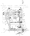
- Figure 1 shows a view in perspective, with parts removed for clarity, of a packing unit for producing aseptic sealed packages containing pourable food products from a tube of packing material and according to the method of the present invention;
- Figure 2 shows a side view, with parts removed for clarity, of the Figure 1 unit;
- Figure 3 shows a side view of the Figure 2 unit in a different operating configuration;
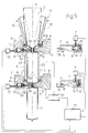
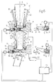
- Figures 4 to 6 show larger-scale side views of two forming assemblies of the Figure 1 unit at various stages in the processing of the tube of packing material:
- Figure 7 shows a larger-scale section of an induction heating element of the Figure 4-6 forming assemblies;
- Figure 8 shows a larger-scale section of a variation of the Figure 7 induction heating element.
-
-
Number 1 in Figures 1 to 3 indicates as a whole a packing unit for producing, from atube 3 of packing material, aseptic sealed packages 2 (Figures 4 to 6) containing a pourable food product, such as pasteurized or UHT milk, fruit juice, wine, etc. - The packing material has a multilayer structure (not shown), and comprises a layer of fibrous material, normally paper, covered on both sides with respective layers of heat seal plastic material, e.g. polyethylene. The side of the packing material eventually contacting the food product in
package 2 also comprises a layer of electrically conductive barrier material, e.g. aluminium, in turn covered with one or more layers of heat seal plastic material. - Tube 3 is formed in known manner upstream from
unit 1 by longitudinally folding and sealing a strip of heat seal strip material, is filled with the sterilized or sterile-processed food product for packaging, and is fed by known devices (not shown) along a vertical path defined by an axis A. -
Unit 1 comprises a supporting structure 4 defining a pair of cylindricalvertical guides 5, 5' located symmetrically with respect to the longitudinal vertical mid-plane α ofunit 1 through axis A (Figure 1). - With reference to Figures 1 to 6,
unit 1 comprises in known manner a pair of formingassemblies 6, 6' movable vertically alongrespective guides 5, 5' and which interact cyclically and successively withtube 3 of packing material to grip equally spaced cross sections of the tube and perform cutting and heat seal operations ontube 3 as described in detail later on. - As
assemblies 6, 6' are known and symmetrical with respect to plane α, only one (assembly 6) will be described, and only as regards the parts pertinent to the present invention. The corresponding parts ofassemblies 6, 6' are indicated in the drawings using the same numbering system. -
Assembly 6 substantially comprises aslide 7 movable alongrespective guide 5; and a pair ofjaws - More specifically, each
jaw quadrangular base portion 10 hinged at the bottom end to a bottom portion ofslide 7; and anarm 11 for interacting withtube 3, and which is fixed to the top end ofportion 10 and projects fromportion 10 in a direction perpendicular to plane α.Arms 11 ofjaws tube 3. - At
respective portions 10,jaws integral transmission members 12 in the form of sector gears, which mesh with each other so that the rotation of one ofjaws other jaw -
Assembly 6 also comprises afirst hook element 13 integral withportion 10 of one (9) of the jaws; asecond hook element 14 hinged toportion 10 of the other jaw (8) about an axis D parallel to axes B, C; and ahydraulic cylinder 15 forengaging hook elements jaws tube 3. - More specifically,
hook elements respective teeth Cylinder 15 comprises apiston 19 extending integrally fromhook element 14 at the opposite end tohook element 13, and which slides in sealed manner inside anouter jacket 20 and is normally pushed towardshook element 13 by aspring 21 housed insidejacket 20, so that, when disconnectinghook elements teeth 16 and 17 (Figures 4 and 5 relative to assembly 6'). When oil under pressure is fed intojacket 20 through an inlet incylinder 15,spring 21 is compressed to engageteeth assembly 6, and Figure 6 relative to assembly 6'). -
Jaws slide 7 moving alongguide 5, and also perform an opening and closing movement abouttube 3 of packing material by rotating about respective hinge axes B, C between the jaws andslide 7. The opening and closing movement is superimposed on the up and down vertical movement ofslide 7. - The vertical movement and the opening and closing movement are controlled respectively by a first and second known cam actuating
device - With reference to Figures 1 to 3,
actuating device 25 comprises acam 27 rotating about a respective axis E parallel to axes B, C, D; a substantiallyvertical lever 28 hinged at the bottom to a top portion ofslide 7; and a substantially horizontalrocker arm lever 29, which is located overcam 27, is hinged at opposite ends to lever 28 and to structure 4, and cooperates with the outer profile ofcam 27 by means of a respectiveintermediate idle roller 30. - Rocker arm levers 29 of
assemblies 6, 6' are also connected to each other and to structure 4 by alever mechanism 31, so thatrollers 30 ofrocker arm levers 29 are kept contactingrespective cams 27 at all times.Lever mechanism 31 comprises a pair of substantiallyvertical rods 32 hinged at the top to respective rocker arm levers 29, and at the bottom to atransverse lever 33 in turn hinged centrally to structure 4 about an axis perpendicular to axes A, B, C, D. More specifically, eachrod 32 is hinged to respectiverocker arm lever 29 in an intermediate position betweenrespective roller 30 andrespective lever 28. - Actuating
device 26 comprises acam 35 having an axis E and defining, on the outer face, a first and secondannular groove respective lever mechanisms jaws teeth hook elements - More specifically,
lever mechanism 38 comprises a substantially verticalfirst rod 40 hinged at the top end to structure 4 and supporting a projectingidle roller 41 engaging inrolling manner groove 36 ofcam 35; and asecond rod 42 extending parallel to plane α and crosswise to axis A, and hinged at opposite ends tojaw 8 about axis D, and to the bottom end ofrod 40. -
Lever mechanism 39 comprises a substantially verticalfirst rod 43 hinged at the top end to structure 4 and supporting a projectingidle roller 44 engaging inrolling manner groove 37 ofcam 35; and a tubularsecond rod 45 fitted in axially-sliding manner onrod 42 and hinged at opposite ends, by means of respective connectingrods rod 43 and to hookelement 14, at a point below axis D. - Since, as stated previously, the vertical movement of
slide 7 and the opening and closing movement ofjaws lever 28 moves reciprocatingly, whilerods lever 28 and a further component of periodic motion for opening and closingjaws - With reference to Figures 2 to 6,
assembly 6 also comprises two mutually facing formingtabs 50 hinged torespective jaws package 2 to be formed in between.Tabs 50 are closed by known cams (not shown) fixed to structure 4 ofunit 1, and which interact with respective rollers (not shown) ontabs 50. - With reference to Figures 4 to 7,
assembly 6 also comprises asealing device 51 and acutting device 52, which, for each cross section oftube 3 of packing material gripped betweenrespective jaws - With reference to Figures 4 and 7 in particular,
device 51 comprises a substantially U-shapedinduction heating element 53 housed in a similarly shapedfront groove 54 formed inarm 11 ofjaw 8. -
Heating element 53 has a substantially ring-shaped cross section; an inner cavity for the passage of coolant; and a pair of straight, elongatedactive surfaces 55, which interact withtube 3 and extend on opposite sides of and parallel to an intermediate plane π perpendicular to axis A and coinciding, in use, with parting line L of the cross section oftube 3 gripped betweenjaws -
Heating element 53 also comprises a pair of straightlongitudinal projections 56 projecting from respectiveactive surfaces 55 towardsjaw 9, extending substantially the whole length ofactive surfaces 55, and which, during heat sealing, provide for increasing the gripping pressure ontube 3. -
Heating element 53 is supplied in known manner by an electriccurrent generator 57 shown schematically in Figures 4 to 6. -
Device 51 also comprises a pair of pressure pads 58 (Figure 4), which are normally made of elastic material, are fitted to the front ofjaw 9, and cooperate with respectiveactive surfaces 55 ofheating element 53 to grip andheat seal tube 3 on opposite sides of plane π. - With reference to Figures 4 to 6,
device 52 comprises a substantiallyflat cutting element 59 housed in sliding manner in afront seat 60 onjaw 9 and movable in a direction perpendicular to plane α; and ahydraulic cylinder 61 for activating cuttingelement 59 and built intojaw 9. - More specifically,
cylinder 61 comprises apiston 62 integral with cuttingelement 59 and movable inside achamber 63 formed in the body ofjaw 9 and communicating on one side withseat 60 and on the opposite side with a pressurized oil inlet. Cuttingelement 59 is normally maintained in a withdrawn idle position, fully housed inside seat 60 (Figures 5 and 6), by aspring 64 housed insidechamber 63 and interposed betweenpiston 62 and awall separating chamber 63 fromseat 60, and is moved by pressurized oil into a forward cutting position (Figure 4) projecting frontwards fromjaw 9 and cooperating with a cavity injaw 8. -
Unit 1 also comprises a central control unit 70 (Figures 4 to 6) connected togenerator 57 and tocylinders solenoid valves - According to the present invention,
central control unit 70 provides, whentube 3 is gripped by each pair ofjaws respective generator 57 and thecontrol cylinder 61 ofrespective cutting element 59 according to a predetermined program memorized inunit 70 itself, so as to first cut the cross section oftube 3 gripped betweenjaws tube 3 on opposite sides of parting line L. - Operation of
unit 1, which is partly self-explanatory from the above description, is as follows. - As each
assembly 6, 6' travels downwards,jaws assembly 6, 6' move into the closed position to griptube 3 with a downward vertical component of motion equal to the traveling speed oftube 3. As they travel downwards,jaws grip tube 3 tightly bycentral control unit 70 activatingcylinder 15, and in particular by the movement ofpiston 19 engagingteeth hook elements gripping jaws - At this stage,
central control unit 70 activatescylinder 61 to move cuttingelement 59 from the withdrawn to the forward position to cut the cross section oftube 3 of packing material gripped betweenjaws - Once
cylinder 61 is deactivated, and hence cuttingelement 59 restored to the withdrawn position byspring 64,central control unit 70 activatesgenerator 57 to supply electric current toheating element 53 and so heatseal tube 3 of packing material on opposite sides of parting line L (Figure 5). - During this stage,
heating element 53 melts the plastic heat seal layer of the packing material locally; and the electric current supply toheating element 53 is cut off while maximum pressure is still being exerted byjaws tube 3, so that cooling and consequent setting, on which the seal depends, of the plastic layer commence under pressure to ensure perfect sealing ofpackages 2. - Close to the bottom dead center position,
central control unit 70 deactivatescylinder 15 to releasehook elements open jaws 8 and 9 - which are opened fully as they travel upwards - and release tube 3 (Figure 6). - The movement of
assemblies 6, 6' is obviously offset by half a cycle :assembly 6 withjaws jaws arms 11 of assembly 6' pass betweenarms 11 ofassembly 6 with no interference. - Inverting the cutting and heat sealing of
tube 3 of packing material as compared with the known methods described previously alters the path of the loss currents induced in the packing material byheating element 53. - That is, as parting line L formed by cutting
element 59 intube 3 of packing material produces an interruption in the electric continuity of the aluminium sheet, the electric loss currents induced in the packing material by the twoactive surfaces 55 ofheating element 53 are confined on opposite sides of parting line L. In other words, the electric loss current induced in the packing material by one ofactive surfaces 55 ofheating element 53 on one side of parting line L tends to move towards the otheractive surface 55 ofheating element 53, but, on account of the interruption produced in the packing material, is forced to close its path on the same side of parting line L. - As a result, the sealing area on both sides of parting line L is more or less constant, by eliminating the bending-off effect of the electric loss current close to the edges of the cross section gripped between
jaws - The Figure 8 variation relates to an
induction heating element 75 similar toheating element 53, but comprising two straightactive surfaces active surface 55. - More specifically,
heating element 75 comprises a substantially U-shapedfirst body 77, which is housed in a similarly shapedfront groove 78 formed inarm 11 ofjaw 8,.has a substantially ring-shaped cross section, and defines, externally, twoactive surfaces 76a on opposite sides of plane π. -
Heating element 75 also comprises asecond body 79, which is defined by a straight bar having a U-shaped cross section and housed in anintermediate recess 80 injaw 8, and defines twoactive surfaces 76b on opposite sides of mid-plane π and interposed betweenactive surfaces 76a. - Like
heating element 53,heating element 75 comprises four straightlongitudinal projections jaw 9 from respectiveactive surfaces - Using
heating element 75, the electric loss current induced in the packing material has been found to follow substantially symmetrical closed paths on opposite sides of parting line L. More specifically, on each side of parting line L, the electric loss current travels linearly along eachactive surface heating element 75, with only a minimum amount of deflection close to the edges of the packing material, and which, involving only a very small part of the sealing region, is practically negligible. The method according to the present invention has been found by the Applicant to produce sealed pourablefood product packages 2 in which the full height of the transverse sealing region is completely sealed. - As stated above, in known techniques, two contiguous packages are usually sealed transversely along two parallel lines before being separated along line L.
- The Applicant, on the other hand, has found it more advantageous to separate the packages unsealed and simply compressed between the sealing and elastic contrasting elements, which provides for expelling the small amount of product compressed between the two projections, and so bringing the two layers of heat seal material even closer together to improve the seal.
- Using
heating element 53 with twoactive surfaces 55, the two edges cut by cuttingelement 59 but still close together may possibly be traversed by currents in opposite directions, thus resulting in short circuiting - also aided by the presence of the usually conductive product - with the surrounding metal masses, and in less than perfectly reliable operation of the packing unit. - Using
heating element 75 with fouractive surfaces element 59 penetrating along a line of symmetry of the currents with no possibility of affecting the amplitude or direction of the currents, thus enabling the product to be expelled and improving both sealing and the reliability of the packing unit itself. - Tests conducted by the Applicant have also shown that using
heating element 75 with fouractive surfaces projections tube 3 of packing material cut prior to heat sealing.Projections - Clearly, changes may be made to
unit 1 as described herein without, however, departing from the scope of the accompanying Claims. - Though particularly advantageous for sealing packing material by induction of electric current, the method described also applies to other sealing processes.
Claims (14)
- A method of producing sealed packages (2) containing pourable food products from a tube (3) of heat seal sheet packing material fed along a vertical path (A) and filled continuously with said food product; said method comprising the steps of:pressure gripping equally spaced cross sections of said tube (3) by means of at least two pairs of jaws (8, 9) acting cyclically and successively on the tube (3);cutting said tube (3), at each of said cross sections, along a respective parting line (L); and thenheat sealing the packing material of said tube (3) on opposite sides of said parting line (L).
- A method of producing sealed packages (2) containing pourable food products from a tube (3) of heat seal sheet packing material fed along a vertical path (A) and filled continuously with said food product; said method comprising the steps of:characterized in that said heat seal step is performed by inducing, on opposite sides of said parting line (L) of said tube (3) of packing material, electric loss currents traveling along substantially symmetrical paths with respect to the parting line (L).pressure gripping equally spaced cross sections of said tube (3) by means of at least two pairs of jaws (8, 9) acting cyclically and successively on the tube (3);cutting said tube (3), at each of said cross sections, along a respective parting line (L); andheat sealing the packing material of said tube (3) on opposite sides of said parting line (L);
- A method as claimed in Claim 1 or 2, for aseptic sealed packages (2) made of heat seal packing material comprising at least one layer of electrically conductive barrier material; characterized in that said heat seal step is performed by inducing electric loss current in said packing material of said tube (3).
- A packing unit (1) for producing sealed packages (2) containing pourable food products from a tube (3) of heat seal sheet packing material fed along a vertical path (A) and filled continuously with said food product, said unit (1) comprising a fixed structure (4); at least two pairs of jaws (8, 9) movable with respect to said structure (4) and acting cyclically and successively on said tube (3) to pressure grip equally spaced cross sections of the tube; and sealing means (51) and cutting means (52) carried by each said pair of jaws (8, 9) to respectively perform, on each said cross section of said tube (3) of packing material gripped between the jaws (8, 9), a heat seal operation and a cutting operation along a respective parting line (L);
characterized by comprising control means (70) for controlling said jaws (8, 9), said sealing means (51) and said cutting means (52) to perform, on said tube (3) of packing material, first said cutting operation along said parting line (L) and then said heat seal operation on opposite sides of the parting line (L). - A packing unit (1) for producing sealed packages (2) containing pourable food products from a tube (3) of heat seal sheet packing material fed along a vertical path (A) and filled continuously with said food product, said unit (1) comprising a fixed structure (4); at least two pairs of jaws (8, 9) movable with respect to said structure (4) and acting cyclically and successively on said tube (3) to pressure grip equally spaced cross sections of the tube; and sealing means (51) and cutting means (52) carried by each said pair of jaws (8, 9) to respectively perform, on each said cross section of said tube (3) of packing material gripped between the jaws (8, 9), a heat seal operation and a cutting operation along a respective parting line (L); characterized in that said sealing means (51) comprise heating means (53, 75) in turn comprising, for each pair of said jaws (8, 9), at least two elongated active surfaces (55, 76a, 76b) interacting with each said cross section of said tube (3) gripped between the jaws (8, 9), and located on opposite sides of the respective said parting line (L).
- A unit as claimed in Claim 4 or 5, for aseptic sealed packages (2) made of packing material comprising at least one layer of electrically conductive barrier material; characterized in that said sealing means (51) comprise electric-current-induction heating means (53, 75) carried by one (8) of said jaws (8, 9) in each pair; contrasting means (58) carried by the other (9) of said jaws (8, 9) in said pair and cooperating with said heating means (53, 75); and electric current generating means (57) for supplying said heating means (53, 75).
- A unit as claimed in Claim 6, characterized in that said layer of electrically conductive material of said packing material is made of aluminium.
- A unit as claimed in Claim 6 or 7, characterized in that said heating means (53, 75) comprise, for each pair of said jaws (8, 9), at least two elongated active surfaces (55, 76a, 76b) interacting with each said cross section of said tube (3) gripped between the jaws (8, 9), and located on opposite sides of the respective said parting line (L).
- A unit as claimed in Claim 8, characterized in that said heating means (75) comprise, for each pair of said jaws (8, 9), four elongated said active surfaces (76a, 76b) interacting with each said cross section of said tube (3) gripped between the jaws (8, 9), and located in pairs on opposite sides of the respective said parting line (L); said active surfaces (76a, 76b) inducing, on opposite sides of said parting line (L) of each said cross section of said tube (3) of packing material, electric loss currents traveling along substantially symmetrical paths with respect to the parting line (L).
- A unit as claimed in Claim 8 or 9, characterized in that said heating means (53, 75) comprise, for each said active surface (55, 76a, 76b), a projection (56, 81) projecting frontwards from the active surface (55, 76a, 76b) and extending substantially the whole length of the active surface.
- A unit as claimed in any one of Claims 4 to 10, characterized in that said cutting means (52) comprise at least one cutting element (59) carried by one (9) of said jaws (8, 9) in each pair and movable, with respect to the jaws (8, 9), crosswise to said tube (3) of packing material; and first actuating means (61) for moving said cutting element (59) between an idle position, and a cutting position in which the cutting element projects frontwards from the respective said jaw (9).
- A unit as claimed in any one of Claims 4 to 11, characterized by comprising first and second hook means (13, 14) carried by respective said jaws (9, 8) in each pair; and second actuating means (15) for pressure engaging said first and second hook means (13, 14) in an engaged position corresponding to a closed position of the jaws (8, 9) on said tube (3) of packing material.
- A unit as claimed in Claim 12, characterized in that said control means comprise a central control unit (70) connected to said first and second actuating means (61, 15) and to said electric current generator (57).
- A sealed package (2) containing a pourable food product, produced according to the method defined in Claims 1, 2 or 3, and comprising a transverse sealing region; characterized in that the full height of said transverse sealing region is sealed completely.
Priority Applications (17)
| Application Number | Priority Date | Filing Date | Title |
|---|---|---|---|
| ES98830588T ES2257800T3 (en) | 1998-10-07 | 1998-10-07 | METHOD FOR PRODUCING SEALED CONTAINERS CONTAINING FOOD PRODUCTS THAT CAN BE SEEN FROM A PACKING MATERIAL PIPE, AND PACKING UNIT THAT IMPLEMENTS SUCH METHOD. |
| DE69833480T DE69833480T2 (en) | 1998-10-07 | 1998-10-07 | Method and device for producing sealed packages of flowable foodstuffs from tubular packaging material |
| AT98830588T ATE317796T1 (en) | 1998-10-07 | 1998-10-07 | METHOD AND DEVICE FOR PRODUCING SEALED PACKAGINGS OF FLOWABLE FOODS FROM TUBULAR PACKAGING MATERIAL |
| EP98830588A EP0992431B1 (en) | 1998-10-07 | 1998-10-07 | Method of producing sealed packages containing pourable food products from a tube of packing material, and packing unit implementing such a method |
| AU63350/99A AU6335099A (en) | 1998-10-07 | 1999-10-06 | Method of producing sealed packages containing pourable food products from a tube of packing material, and packing unit implementing such a method |
| UA2001042283A UA72474C2 (en) | 1998-10-07 | 1999-10-06 | Method of producing sealed packages containing pourable food products from a tube of packing material, hermetic package and packing device |
| US09/806,935 US6877295B1 (en) | 1998-10-07 | 1999-10-06 | Method of producing sealed packages containing pourable food products from a tube of packing material, and packing unit implementing such a method |
| RU2001112108/12A RU2253599C2 (en) | 1998-10-07 | 1999-10-06 | Method for sealed packages containing pourable food products manufacturing of packing material sleeve and device for above method realization |
| PCT/EP1999/007505 WO2000020279A1 (en) | 1998-10-07 | 1999-10-06 | Method of producing sealed packages containing pourable food products from a tube of packing material, and packing unit implementing such a method |
| JP2000574414A JP4445134B2 (en) | 1998-10-07 | 1999-10-06 | Method for producing a sealed package containing injectable food from a tube of packing material and a packing unit implementing this method |
| IDW20010783A ID28152A (en) | 1998-10-07 | 1999-10-06 | THE METHOD OF PRODUCING SEALED PACKAGING THAT CONTAINS FOOD PRODUCTS CAN BE SUPPORTED FROM THE PACKAGING MATERIAL TUBE, AND THE PACKAGING UNIT THAT APPLIES THE METHOD LIKE THAT |
| BR9914334-8A BR9914334A (en) | 1998-10-07 | 1999-10-06 | Packing process and unit to produce sealed packaging containing disposable food products from a tube and sealed packaging |
| HU0103737A HU228279B1 (en) | 1998-10-07 | 1999-10-06 | Method of producing sealed packages containing pourable food products from a tube of packing material, and packing unit implementing such a method |
| HK02103510.3A HK1041857B (en) | 1998-10-07 | 1999-10-06 | A method of producing sealed packages, a packing unit for producing sealed packages and a sealed package containing a pourable food product |
| TR2001/00968T TR200100968T2 (en) | 1998-10-07 | 1999-10-06 | Method and packaging unit for the production of closed packages |
| KR1020017003905A KR100786952B1 (en) | 1998-10-07 | 1999-10-06 | A method for producing a sealed package containing pourable food from a tube of packaging material and a packing unit for performing the method |
| CNB998119377A CN1281460C (en) | 1998-10-07 | 1999-10-06 | Method of producing sealed packages containing pourable food products from tube of packing material, and packing unit implementing said method |
Applications Claiming Priority (1)
| Application Number | Priority Date | Filing Date | Title |
|---|---|---|---|
| EP98830588A EP0992431B1 (en) | 1998-10-07 | 1998-10-07 | Method of producing sealed packages containing pourable food products from a tube of packing material, and packing unit implementing such a method |
Publications (2)
| Publication Number | Publication Date |
|---|---|
| EP0992431A1 true EP0992431A1 (en) | 2000-04-12 |
| EP0992431B1 EP0992431B1 (en) | 2006-02-15 |
Family
ID=8236818
Family Applications (1)
| Application Number | Title | Priority Date | Filing Date |
|---|---|---|---|
| EP98830588A Expired - Lifetime EP0992431B1 (en) | 1998-10-07 | 1998-10-07 | Method of producing sealed packages containing pourable food products from a tube of packing material, and packing unit implementing such a method |
Country Status (16)
| Country | Link |
|---|---|
| US (1) | US6877295B1 (en) |
| EP (1) | EP0992431B1 (en) |
| JP (1) | JP4445134B2 (en) |
| KR (1) | KR100786952B1 (en) |
| CN (1) | CN1281460C (en) |
| AT (1) | ATE317796T1 (en) |
| AU (1) | AU6335099A (en) |
| BR (1) | BR9914334A (en) |
| DE (1) | DE69833480T2 (en) |
| ES (1) | ES2257800T3 (en) |
| HU (1) | HU228279B1 (en) |
| ID (1) | ID28152A (en) |
| RU (1) | RU2253599C2 (en) |
| TR (1) | TR200100968T2 (en) |
| UA (1) | UA72474C2 (en) |
| WO (1) | WO2000020279A1 (en) |
Cited By (7)
| Publication number | Priority date | Publication date | Assignee | Title |
|---|---|---|---|---|
| EP1234772A1 (en) | 2001-02-23 | 2002-08-28 | Tetra Laval Holdings & Finance SA | Packaging machine and method for producing sealed packages of pourable food products |
| WO2002102574A1 (en) * | 2001-06-18 | 2002-12-27 | Tetra Laval Holdings & Finance Sa | Induction sealing device for heat sealing packaging material |
| EP1533106A3 (en) * | 2003-11-14 | 2006-01-18 | OPM S.p.A. | Product packing assembly, in particular for packing food products |
| EP1795447A1 (en) * | 2005-12-12 | 2007-06-13 | Tetra Laval Holdings & Finance SA | Packaging unit for producing sealed packages of pourable food products from a tube of packaging material |
| EP2311738A1 (en) * | 2009-10-15 | 2011-04-20 | Tetra Laval Holdings & Finance SA | A packaging machine for producing sealed packages of pourable food products |
| GB2481620A (en) * | 2010-07-01 | 2012-01-04 | Sheng-Nan Guo | Vertical vacuum packing machine |
| CN102056806B (en) * | 2008-06-09 | 2012-07-04 | 利乐拉瓦尔集团及财务有限公司 | Packaging and filling apparatus |
Families Citing this family (37)
| Publication number | Priority date | Publication date | Assignee | Title |
|---|---|---|---|---|
| DK174177B1 (en) * | 2000-08-16 | 2002-08-12 | Claus Thomsen | Device and method for netting trees |
| JP4007803B2 (en) * | 2001-12-05 | 2007-11-14 | 日本テトラパック株式会社 | Sealing device |
| ES2266382T3 (en) | 2002-10-24 | 2007-03-01 | TETRA LAVAL HOLDINGS & FINANCE S.A. | WELDING GRIP. |
| EP1674397A4 (en) * | 2003-10-14 | 2011-03-02 | Tetra Laval Holdings & Finance | PACKAGING FILLING MACHINE AND SIDE SEALING MACHINE |
| DE60307473T2 (en) * | 2003-10-22 | 2007-02-15 | Tetra Laval Holdings & Finance S.A. | Forming and sealing unit for a machine for packaging liquid foods |
| EP1757523A4 (en) | 2004-04-30 | 2010-07-21 | Orihiro Eng Co Ltd | Vertical filling-packaging machine and method of manufacturing packaging bag |
| JP3990680B2 (en) * | 2004-04-30 | 2007-10-17 | オリヒロエンジニアリング株式会社 | Vertical filling and packaging machine |
| CN100404376C (en) * | 2005-05-08 | 2008-07-23 | 上海交通大学 | Pressure adjustable pressure sealing device |
| CN100548810C (en) * | 2005-06-15 | 2009-10-14 | 利乐拉瓦尔集团及财务有限公司 | The apparatus and method that are used for Production and Packaging |
| SE528880C2 (en) * | 2005-07-04 | 2007-03-06 | Tetra Laval Holdings & Finance | Method and apparatus for supplying a gas or gas mixture |
| ATE522343T1 (en) * | 2007-06-28 | 2011-09-15 | Tetra Laval Holdings & Finance | INDUCTION SEALING DEVICE FOR HEAT SEALING PACKAGING MATERIAL FOR PRODUCING SEALED PACKAGINGS FOR POURABLE FOOD PRODUCTS |
| ES2357977T3 (en) * | 2007-09-28 | 2011-05-04 | TETRA LAVAL HOLDINGS & FINANCE SA | MEMBER TO FORM SEALED CONTAINERS OF VERTIBLE FOOD PRODUCTS FROM A PACKING MATERIAL PIPE. |
| EP2113371A1 (en) * | 2008-04-29 | 2009-11-04 | Tetra Laval Holdings & Finance SA | Sealing jaw for producing sealed packages of a food product |
| EP2151390B1 (en) * | 2008-08-09 | 2015-09-30 | Tetra Laval Holdings & Finance S.A. | Packaging method and unit for producing sealed packages of a food product pourable into a tube of packaging material |
| RU2393979C1 (en) * | 2009-03-10 | 2010-07-10 | Закрытое акционерное общество "БЕСТРОМ" | Method of fabricating and sealing bags made from heat sealing material |
| GB2469814B (en) * | 2009-04-28 | 2013-07-17 | Cash Dynamics Ltd | A bag and sealing method and apparatus |
| CN102101549A (en) * | 2009-12-18 | 2011-06-22 | 利乐拉瓦尔集团及财务有限公司 | Package forming device |
| DE102010005849B4 (en) | 2010-01-26 | 2012-04-19 | Sig Technology Ag | Method for producing a container for foods made of an aluminum-free sheet-like composite with an inner layer by means of hot folds |
| GB2482713B (en) * | 2010-08-12 | 2012-10-03 | Frito Lay Trading Co Gmbh | Packaging apparatus including rotary jaw device and method of making packages |
| JP5554727B2 (en) * | 2010-12-14 | 2014-07-23 | 株式会社イシダ | Goods transfer device |
| ITVR20110098A1 (en) * | 2011-05-11 | 2012-11-12 | P F M Spa | VERTICAL PACKAGING MACHINE FOR FOOD PRODUCTS |
| DE102011108402A1 (en) | 2011-07-26 | 2013-01-31 | Sig Technology Ag | SURFACE CONNECTION WITH PLASTIC LAYERS OF DIFFERENT VICAT IMPROVEMENT TEMPERATURES |
| DE102011108401A1 (en) | 2011-07-26 | 2013-01-31 | Sig Technology Ag | Robust laminar composite with an intermediate layer with increased Vicat softening temperature |
| USD665551S1 (en) | 2011-09-19 | 2012-08-14 | Scandinavian Child Llc | Heat-sealed waste disposal |
| EP2662291B1 (en) * | 2012-05-11 | 2014-10-15 | Tetra Laval Holdings & Finance S.A. | Packaging unit and method for producing sealed packages |
| CA2898541C (en) * | 2014-07-29 | 2022-06-28 | Nicoletta Razzaboni | Device for filling and closing bags for containing paper documents, such as banknotes and the like |
| KR101519090B1 (en) * | 2014-11-07 | 2015-05-11 | 정규봉 | Pipe bender with improved angle gauge |
| RU2577116C1 (en) * | 2015-06-25 | 2016-03-10 | Олег Иванович Квасенков | Method for producing kvass |
| US10737443B2 (en) | 2015-08-31 | 2020-08-11 | Elopak As | Device and method for inductive sealing of a plurality of plies of a laminate |
| EP3478587B1 (en) * | 2016-06-30 | 2020-08-26 | Topocare GmbH | Device for producing tubular containers |
| DE102016213087B4 (en) * | 2016-07-18 | 2018-07-05 | Rovema Gmbh | Method for operating a tubular bag machine for the production of bags with a bottom cross seam and a different head cross seam |
| US11148839B2 (en) * | 2017-04-07 | 2021-10-19 | Becton Dickinson Rowa Germany Gmbh | Device for packing drug portions |
| CN108408097B (en) * | 2018-03-14 | 2020-11-13 | 山东碧海包装材料有限公司 | Filling method for liquid with particles |
| US12122547B2 (en) * | 2019-02-05 | 2024-10-22 | Tetra Laval Holdings & Finance S.A. | Induction heat sealing device and a method for transversally seal a tube of packaging material |
| IT201900007272A1 (en) * | 2019-05-27 | 2020-11-27 | Gd Spa | Container forming machine for pourable products |
| CN113148267B (en) * | 2021-04-16 | 2023-04-11 | 山东华畅食品股份有限公司 | Tomato sauce bag processing equipment |
| CN119037827B (en) * | 2024-11-01 | 2025-03-07 | 泰州益谷气食品科技有限公司 | Food packaging equipment for food processing |
Citations (5)
| Publication number | Priority date | Publication date | Assignee | Title |
|---|---|---|---|---|
| US4109792A (en) * | 1973-04-04 | 1978-08-29 | The Dow Chemical Company | Method of packaging and product made thereby |
| US4637199A (en) * | 1985-01-30 | 1987-01-20 | International Paper Company | Induction sealing of paperboard |
| EP0460540A1 (en) * | 1990-06-06 | 1991-12-11 | Tetra Laval Holdings & Finance SA | A forming device in packaging machines |
| US5755076A (en) * | 1993-05-06 | 1998-05-26 | Tetra Laval Holdings & Finance S.A. | Heat sealing bar |
| EP0887269A1 (en) * | 1997-06-27 | 1998-12-30 | Tetra Laval Holdings & Finance SA | Packaging unit for continuously producing sealed packages containing pourable food products, and method of monitoring a sealing operation performed on the packaging unit |
Family Cites Families (19)
| Publication number | Priority date | Publication date | Assignee | Title |
|---|---|---|---|---|
| NL292674A (en) * | 1961-10-11 | 1900-01-01 | ||
| US3538676A (en) * | 1967-03-08 | 1970-11-10 | William R Runo | Packaging machine |
| US3874976A (en) * | 1973-02-02 | 1975-04-01 | Computron Inc | Gripper jaw assembly |
| US4106261A (en) * | 1977-08-08 | 1978-08-15 | The Dow Chemical Company | Method of forming, filling, and sealing scrim reinforced plastic bags |
| US4350003A (en) * | 1980-03-13 | 1982-09-21 | Package Machinery Company | Sealing head |
| US4512138A (en) * | 1982-03-04 | 1985-04-23 | The Dow Chemical Company | Form, fill and seal machine with hot gas and thermal impulse sealing |
| SE454167B (en) | 1982-09-27 | 1988-04-11 | Tetra Pak Ab | SET AND DEVICE FOR MANUFACTURING PACKAGING CONTAINERS |
| JPS6061570A (en) | 1983-09-16 | 1985-04-09 | Sankyo Co Ltd | Pyridazinone derivative and fungicide for agricultural purpose |
| SE451829C (en) | 1984-02-16 | 1993-03-01 | Fidex Maskin Ab | SET AND DEVICE FOR CONTINUOUS HEAT TREATMENT AND PACKAGING OF SCIENTIFIC PRODUCT |
| SE437136B (en) | 1984-03-08 | 1985-02-11 | Tetra Pak Int | SET AND DEVICE FOR MANUFACTURING AND FILLING OF PACKAGING CONTAINERS |
| DE3420711A1 (en) | 1984-06-02 | 1985-12-05 | Tetra Pak Developpement S.A., Pully | MACHINE FOR PRODUCING FLUID PACKS |
| SE454770B (en) | 1984-07-31 | 1988-05-30 | Tetra Dev Co | VALVE ARRANGEMENTS AT THE PACKAGING MACHINE |
| SE448444B (en) | 1985-07-08 | 1987-02-23 | Alfa Laval Food & Dairy Eng | CLOSABLE PHASE AND USE OF THIS |
| US5284002A (en) * | 1992-02-25 | 1994-02-08 | Simple Packaging Solutions, Inc. | Apparatus and method for making a reclosable storage bag |
| SE508369C2 (en) * | 1993-10-07 | 1998-09-28 | Tetra Laval Holdings & Finance | Method and apparatus for making bag packages |
| CH687601A5 (en) | 1994-02-04 | 1997-01-15 | Tetra Pak Suisse Sa | Process for the production of internally sterile packaging with excellent barrier properties. |
| US5564255A (en) | 1994-09-28 | 1996-10-15 | Tetra Laval Holdings & Finance S.A. | Apparatus and method for sealing and creasing gabled containers |
| US5673534A (en) * | 1995-06-23 | 1997-10-07 | Simple Packaging Solutions, Inc. | Reclosable storage bag |
| JP3983852B2 (en) * | 1997-07-09 | 2007-09-26 | 四国化工機株式会社 | Web sealing method and apparatus, and packaging container manufacturing method and packaging container manufacturing apparatus |
-
1998
- 1998-10-07 DE DE69833480T patent/DE69833480T2/en not_active Expired - Lifetime
- 1998-10-07 AT AT98830588T patent/ATE317796T1/en active
- 1998-10-07 ES ES98830588T patent/ES2257800T3/en not_active Expired - Lifetime
- 1998-10-07 EP EP98830588A patent/EP0992431B1/en not_active Expired - Lifetime
-
1999
- 1999-10-06 AU AU63350/99A patent/AU6335099A/en not_active Abandoned
- 1999-10-06 US US09/806,935 patent/US6877295B1/en not_active Expired - Lifetime
- 1999-10-06 ID IDW20010783A patent/ID28152A/en unknown
- 1999-10-06 KR KR1020017003905A patent/KR100786952B1/en not_active Expired - Fee Related
- 1999-10-06 JP JP2000574414A patent/JP4445134B2/en not_active Expired - Fee Related
- 1999-10-06 BR BR9914334-8A patent/BR9914334A/en not_active IP Right Cessation
- 1999-10-06 TR TR2001/00968T patent/TR200100968T2/en unknown
- 1999-10-06 WO PCT/EP1999/007505 patent/WO2000020279A1/en not_active Ceased
- 1999-10-06 RU RU2001112108/12A patent/RU2253599C2/en not_active IP Right Cessation
- 1999-10-06 CN CNB998119377A patent/CN1281460C/en not_active Expired - Lifetime
- 1999-10-06 HU HU0103737A patent/HU228279B1/en not_active IP Right Cessation
- 1999-10-06 UA UA2001042283A patent/UA72474C2/en unknown
Patent Citations (5)
| Publication number | Priority date | Publication date | Assignee | Title |
|---|---|---|---|---|
| US4109792A (en) * | 1973-04-04 | 1978-08-29 | The Dow Chemical Company | Method of packaging and product made thereby |
| US4637199A (en) * | 1985-01-30 | 1987-01-20 | International Paper Company | Induction sealing of paperboard |
| EP0460540A1 (en) * | 1990-06-06 | 1991-12-11 | Tetra Laval Holdings & Finance SA | A forming device in packaging machines |
| US5755076A (en) * | 1993-05-06 | 1998-05-26 | Tetra Laval Holdings & Finance S.A. | Heat sealing bar |
| EP0887269A1 (en) * | 1997-06-27 | 1998-12-30 | Tetra Laval Holdings & Finance SA | Packaging unit for continuously producing sealed packages containing pourable food products, and method of monitoring a sealing operation performed on the packaging unit |
Cited By (15)
| Publication number | Priority date | Publication date | Assignee | Title |
|---|---|---|---|---|
| US6810644B2 (en) | 2001-02-23 | 2004-11-02 | Tetra Laval Holdings & Finance S.A. | Packaging machine and method for producing sealed packages of pourable food products |
| EP1234772A1 (en) | 2001-02-23 | 2002-08-28 | Tetra Laval Holdings & Finance SA | Packaging machine and method for producing sealed packages of pourable food products |
| RU2291091C2 (en) * | 2001-06-18 | 2007-01-10 | Тетра Лаваль Холдингз Энд Файнэнс Са | Induction welder for thermal welding of packing material |
| EP1270182A1 (en) | 2001-06-18 | 2003-01-02 | Tetra Laval Holdings & Finance S.A. | Induction sealing device for heat sealing packaging material |
| US7059100B2 (en) | 2001-06-18 | 2006-06-13 | Tetra Laval Holdings & Finance Sa | Induction sealing device for heat sealing packaging material |
| WO2002102574A1 (en) * | 2001-06-18 | 2002-12-27 | Tetra Laval Holdings & Finance Sa | Induction sealing device for heat sealing packaging material |
| KR100858595B1 (en) * | 2001-06-18 | 2008-09-17 | 테트라 라발 홀딩스 앤드 피낭스 소시에떼아노님 | Induction sealing device for heat sealing packaging material |
| CN100418736C (en) * | 2001-06-18 | 2008-09-17 | 利乐拉瓦尔集团及财务有限公司 | Induction sealer for heat-sealing packages |
| EP1533106A3 (en) * | 2003-11-14 | 2006-01-18 | OPM S.p.A. | Product packing assembly, in particular for packing food products |
| EP1795447A1 (en) * | 2005-12-12 | 2007-06-13 | Tetra Laval Holdings & Finance SA | Packaging unit for producing sealed packages of pourable food products from a tube of packaging material |
| CN102056806B (en) * | 2008-06-09 | 2012-07-04 | 利乐拉瓦尔集团及财务有限公司 | Packaging and filling apparatus |
| EP2311738A1 (en) * | 2009-10-15 | 2011-04-20 | Tetra Laval Holdings & Finance SA | A packaging machine for producing sealed packages of pourable food products |
| WO2011045395A1 (en) * | 2009-10-15 | 2011-04-21 | Tetra Laval Holdings & Finance S.A. | A packaging machine for producing sealed packages of pourable food products |
| GB2481620A (en) * | 2010-07-01 | 2012-01-04 | Sheng-Nan Guo | Vertical vacuum packing machine |
| GB2481620B (en) * | 2010-07-01 | 2012-08-08 | Sheng-Nan Guo | Vertical vacuum packing machine |
Also Published As
| Publication number | Publication date |
|---|---|
| US6877295B1 (en) | 2005-04-12 |
| ES2257800T3 (en) | 2006-08-01 |
| WO2000020279A1 (en) | 2000-04-13 |
| HUP0103737A2 (en) | 2002-02-28 |
| RU2253599C2 (en) | 2005-06-10 |
| CN1281460C (en) | 2006-10-25 |
| JP2002526344A (en) | 2002-08-20 |
| ID28152A (en) | 2001-05-10 |
| HK1041857A1 (en) | 2002-07-26 |
| BR9914334A (en) | 2001-06-26 |
| KR100786952B1 (en) | 2007-12-17 |
| JP4445134B2 (en) | 2010-04-07 |
| HU228279B1 (en) | 2013-02-28 |
| DE69833480D1 (en) | 2006-04-20 |
| HUP0103737A3 (en) | 2002-03-28 |
| KR20010079935A (en) | 2001-08-22 |
| EP0992431B1 (en) | 2006-02-15 |
| DE69833480T2 (en) | 2006-08-31 |
| UA72474C2 (en) | 2005-03-15 |
| CN1322177A (en) | 2001-11-14 |
| TR200100968T2 (en) | 2001-07-23 |
| ATE317796T1 (en) | 2006-03-15 |
| AU6335099A (en) | 2000-04-26 |
Similar Documents
| Publication | Publication Date | Title |
|---|---|---|
| US6877295B1 (en) | Method of producing sealed packages containing pourable food products from a tube of packing material, and packing unit implementing such a method | |
| EP3476751B1 (en) | A packaging assembly for forming and sealing a plurality of packs containing a pourable food product | |
| US8919081B2 (en) | Packaging method for producing sealed packages of a food product pourable into a tube of packaging material | |
| US7059100B2 (en) | Induction sealing device for heat sealing packaging material | |
| EP1101700B1 (en) | Form and seal unit for a machine for packaging pourable food products | |
| EP1509453B1 (en) | Forming jaw for producing a succession of sealed packages from a tube of sheet packaging material | |
| EP2042433A1 (en) | Member and method for forming sealed packages of pourable food products from a tube of packaging material | |
| EP1325868A1 (en) | Packaging unit for continuously producing sealed packages, containing pourable food products, from a tube of packaging material | |
| EP1526074B1 (en) | Form-and-seal unit for a machine for packaging pourable food products | |
| EP1247637A1 (en) | Heat sealing device for producing sealed pourable food packages | |
| MXPA01002416A (en) | Method of producing sealed packages containing pourable food products from a tube of packing material, and packing unit implementing such a method | |
| EP3351478A1 (en) | Forming member for controlling the volume of packs of pourable food products formed from a tube of packaging material | |
| EP1445196B1 (en) | Forming unit for producing sealed packages from a tube of sheet packaging material filled with a pourable food product | |
| HK1041857B (en) | A method of producing sealed packages, a packing unit for producing sealed packages and a sealed package containing a pourable food product | |
| HK1077791B (en) | A forming unit for producing sealed packages from a tube of sheet packaging material | |
| HK1081924B (en) | Forming jaw for producing a succession of sealed packages from a tube of sheet packaging material |
Legal Events
| Date | Code | Title | Description |
|---|---|---|---|
| PUAI | Public reference made under article 153(3) epc to a published international application that has entered the european phase |
Free format text: ORIGINAL CODE: 0009012 |
|
| AK | Designated contracting states |
Kind code of ref document: A1 Designated state(s): AT CH DE DK ES FR GB IT LI NL PT SE |
|
| AX | Request for extension of the european patent |
Free format text: AL;LT;LV;MK;RO;SI |
|
| 17P | Request for examination filed |
Effective date: 20000913 |
|
| AKX | Designation fees paid |
Free format text: AT CH DE DK ES FR GB IT LI NL PT SE |
|
| 17Q | First examination report despatched |
Effective date: 20020801 |
|
| GRAP | Despatch of communication of intention to grant a patent |
Free format text: ORIGINAL CODE: EPIDOSNIGR1 |
|
| GRAS | Grant fee paid |
Free format text: ORIGINAL CODE: EPIDOSNIGR3 |
|
| GRAA | (expected) grant |
Free format text: ORIGINAL CODE: 0009210 |
|
| AK | Designated contracting states |
Kind code of ref document: B1 Designated state(s): AT CH DE DK ES FR GB IT LI NL PT SE |
|
| PG25 | Lapsed in a contracting state [announced via postgrant information from national office to epo] |
Ref country code: NL Free format text: LAPSE BECAUSE OF FAILURE TO SUBMIT A TRANSLATION OF THE DESCRIPTION OR TO PAY THE FEE WITHIN THE PRESCRIBED TIME-LIMIT Effective date: 20060215 Ref country code: LI Free format text: LAPSE BECAUSE OF FAILURE TO SUBMIT A TRANSLATION OF THE DESCRIPTION OR TO PAY THE FEE WITHIN THE PRESCRIBED TIME-LIMIT Effective date: 20060215 Ref country code: IT Free format text: LAPSE BECAUSE OF FAILURE TO SUBMIT A TRANSLATION OF THE DESCRIPTION OR TO PAY THE FEE WITHIN THE PRE;WARNING: LAPSES OF ITALIAN PATENTS WITH EFFECTIVE DATE BEFORE 2007 MAY HAVE OCCURRED AT ANY TIME BEFORE 2007. THE CORRECT EFFECTIVE DATE MAY BE DIFFERENT FROM THE ONE RECORDED.SCRIBED TIME-LIMIT Effective date: 20060215 Ref country code: CH Free format text: LAPSE BECAUSE OF FAILURE TO SUBMIT A TRANSLATION OF THE DESCRIPTION OR TO PAY THE FEE WITHIN THE PRESCRIBED TIME-LIMIT Effective date: 20060215 |
|
| REG | Reference to a national code |
Ref country code: GB Ref legal event code: FG4D Ref country code: CH Ref legal event code: EP |
|
| REF | Corresponds to: |
Ref document number: 69833480 Country of ref document: DE Date of ref document: 20060420 Kind code of ref document: P |
|
| PG25 | Lapsed in a contracting state [announced via postgrant information from national office to epo] |
Ref country code: SE Free format text: LAPSE BECAUSE OF FAILURE TO SUBMIT A TRANSLATION OF THE DESCRIPTION OR TO PAY THE FEE WITHIN THE PRESCRIBED TIME-LIMIT Effective date: 20060515 Ref country code: DK Free format text: LAPSE BECAUSE OF FAILURE TO SUBMIT A TRANSLATION OF THE DESCRIPTION OR TO PAY THE FEE WITHIN THE PRESCRIBED TIME-LIMIT Effective date: 20060515 |
|
| PG25 | Lapsed in a contracting state [announced via postgrant information from national office to epo] |
Ref country code: PT Free format text: LAPSE BECAUSE OF FAILURE TO SUBMIT A TRANSLATION OF THE DESCRIPTION OR TO PAY THE FEE WITHIN THE PRESCRIBED TIME-LIMIT Effective date: 20060717 |
|
| NLV1 | Nl: lapsed or annulled due to failure to fulfill the requirements of art. 29p and 29m of the patents act | ||
| REG | Reference to a national code |
Ref country code: ES Ref legal event code: FG2A Ref document number: 2257800 Country of ref document: ES Kind code of ref document: T3 |
|
| REG | Reference to a national code |
Ref country code: CH Ref legal event code: PL |
|
| ET | Fr: translation filed | ||
| PLBE | No opposition filed within time limit |
Free format text: ORIGINAL CODE: 0009261 |
|
| STAA | Information on the status of an ep patent application or granted ep patent |
Free format text: STATUS: NO OPPOSITION FILED WITHIN TIME LIMIT |
|
| 26N | No opposition filed |
Effective date: 20061116 |
|
| GBPC | Gb: european patent ceased through non-payment of renewal fee |
Effective date: 20061007 |
|
| PG25 | Lapsed in a contracting state [announced via postgrant information from national office to epo] |
Ref country code: GB Free format text: LAPSE BECAUSE OF NON-PAYMENT OF DUE FEES Effective date: 20061007 |
|
| PGFP | Annual fee paid to national office [announced via postgrant information from national office to epo] |
Ref country code: ES Payment date: 20150915 Year of fee payment: 18 |
|
| PGFP | Annual fee paid to national office [announced via postgrant information from national office to epo] |
Ref country code: AT Payment date: 20150928 Year of fee payment: 18 |
|
| REG | Reference to a national code |
Ref country code: FR Ref legal event code: PLFP Year of fee payment: 19 |
|
| REG | Reference to a national code |
Ref country code: AT Ref legal event code: MM01 Ref document number: 317796 Country of ref document: AT Kind code of ref document: T Effective date: 20161007 |
|
| PG25 | Lapsed in a contracting state [announced via postgrant information from national office to epo] |
Ref country code: AT Free format text: LAPSE BECAUSE OF NON-PAYMENT OF DUE FEES Effective date: 20161007 |
|
| REG | Reference to a national code |
Ref country code: FR Ref legal event code: PLFP Year of fee payment: 20 |
|
| PGFP | Annual fee paid to national office [announced via postgrant information from national office to epo] |
Ref country code: FR Payment date: 20170918 Year of fee payment: 20 |
|
| PGFP | Annual fee paid to national office [announced via postgrant information from national office to epo] |
Ref country code: DE Payment date: 20171004 Year of fee payment: 20 |
|
| PGFP | Annual fee paid to national office [announced via postgrant information from national office to epo] |
Ref country code: IT Payment date: 20171024 Year of fee payment: 20 |
|
| PG25 | Lapsed in a contracting state [announced via postgrant information from national office to epo] |
Ref country code: ES Free format text: LAPSE BECAUSE OF FAILURE TO SUBMIT A TRANSLATION OF THE DESCRIPTION OR TO PAY THE FEE WITHIN THE PRESCRIBED TIME-LIMIT Effective date: 20060215 |
|
| REG | Reference to a national code |
Ref country code: DE Ref legal event code: R071 Ref document number: 69833480 Country of ref document: DE |
|
| REG | Reference to a national code |
Ref country code: ES Ref legal event code: FD2A Effective date: 20181116 |
|
| PG25 | Lapsed in a contracting state [announced via postgrant information from national office to epo] |
Ref country code: ES Free format text: LAPSE BECAUSE OF FAILURE TO SUBMIT A TRANSLATION OF THE DESCRIPTION OR TO PAY THE FEE WITHIN THE PRESCRIBED TIME-LIMIT Effective date: 20161008 |