EP0991104A2 - Cathode ray tube - Google Patents
Cathode ray tube Download PDFInfo
- Publication number
- EP0991104A2 EP0991104A2 EP99302484A EP99302484A EP0991104A2 EP 0991104 A2 EP0991104 A2 EP 0991104A2 EP 99302484 A EP99302484 A EP 99302484A EP 99302484 A EP99302484 A EP 99302484A EP 0991104 A2 EP0991104 A2 EP 0991104A2
- Authority
- EP
- European Patent Office
- Prior art keywords
- deflection coil
- separator
- cathode ray
- ray tube
- vertical
- Prior art date
- Legal status (The legal status is an assumption and is not a legal conclusion. Google has not performed a legal analysis and makes no representation as to the accuracy of the status listed.)
- Granted
Links
Images


Classifications
-
- H—ELECTRICITY
- H01—ELECTRIC ELEMENTS
- H01J—ELECTRIC DISCHARGE TUBES OR DISCHARGE LAMPS
- H01J29/00—Details of cathode-ray tubes or of electron-beam tubes of the types covered by group H01J31/00
- H01J29/46—Arrangements of electrodes and associated parts for generating or controlling the ray or beam, e.g. electron-optical arrangement
- H01J29/82—Mounting, supporting, spacing, or insulating electron-optical or ion-optical arrangements
- H01J29/823—Mounting, supporting, spacing, or insulating electron-optical or ion-optical arrangements around the neck of the tube
- H01J29/826—Deflection arrangements
-
- H—ELECTRICITY
- H01—ELECTRIC ELEMENTS
- H01J—ELECTRIC DISCHARGE TUBES OR DISCHARGE LAMPS
- H01J2229/00—Details of cathode ray tubes or electron beam tubes
- H01J2229/86—Vessels and containers
- H01J2229/8603—Neck or cone portions of the CRT vessel
- H01J2229/8606—Neck or cone portions of the CRT vessel characterised by the shape
- H01J2229/8609—Non circular cross-sections
Definitions
- the present invention relates to a cathode ray tube, and more particularly to a cathode ray tube having a deflection unit capable of efficiently reducing power consumption.
- electron beams emitted from an electron gun are deflected in the horizontal and vertical directions and land on phosphors coated on a screen to display images.
- the electron beams are deflected by the horizontal and vertical magnetic fields generated by a deflection unit mounted on an outer surface of a funnel in a cathode ray tube.
- Such cathode ray tubes are widely used in color television and computer monitors, high definition televisions (HDTVs) and other high-tech devices.
- the deflection frequency should be increased and the depth of the tube should be decreased.
- an increase of the deflection power is necessary so that the cathode ray tube could deflect the electron beams at a wider angle.
- an increase in the deflection frequency and the deflection angle require increased power consumption, causing a problem of magnetic field leakage.
- US Patent No. 3,731,129 discloses a means for reducing a diagonal misconvergence to accomplish a wide deflection angle without increased power consumption.
- the present invention seeks to provide a cathode ray tube having advantages over known cathode ray tubes.
- the present invention provides a deflection unit comprising a horizontal deflection coil having a non-circular cross section, a separator placed outside the horizontal deflection coil, with its inner configuration corresponding to the outer configuration of the horizontal deflection coil, a vertical deflection coil placed outside of the separator with its non-circular cross section corresponding to the outer surface of the separator, and a ferrite core for closely attaching the vertical deflection coil to the separator, with its inner side formed to be similar to the inner configuration of the vertical deflection coil.
- the invention also provides for a deflection unit for use with a cathode ray tube.
- Fig. 1 is a schematic view of a cathode ray tube according to a preferred embodiment of the present invention.
- the cathode ray tube has a cylinderical neck 4 wherein an electron gun 2 is placed, a funnel portion 6, the neck portion 4, and a panel 8 sealed to the funnel portion 6.
- a cone portion is indicated by the reference number 12 in the drawing, on which a deflection unit 10 Is to be mounted.
- the cross-sections of the cone portion 12 changes from circular to substantially rectangular as they move from the neck toward the funnel body.
- Figs. 1 and 2 show a deflection unit 10 of the present invention comprising a saddle-like horizontal deflection coil 14 having a non-circular cross section, a separator 16 placed outside the horizontal deflection coil 14, having its inner configuration corresponding to the outer configuration of the horizontal deflection coil 14, a saddle-like vertical deflection coil 18 placed outside of the separator 16, having non-circular cross sectional form corresponding to the outer surface of the separator 16 and a ferrite core 20 for closely attaching the vertical deflection coil 18 to the separator 16, having its inner side formed similar to the inner configuration of the vertical deflection coil 18.
- the vertical deflection coil 18 as shown in Fig. 3 has its horizontal length L1 and its vertical length L2 at a ratio of 1.0 ⁇ LI/L2 ⁇ 1.3, at which the power consumption of the deflection is most reduced.
- the graph in Fig. 4 shows the ratio of the horizontal length L1 to the vertical length L2 of the vertical deflection coil 18, with Z axis representing the distance from neck seal to the funnel.
- the deflection unit of the present invention with this ratios consumes 20% less power compared to prior devices.
- the horizontal and vertical deflection coils of the deflection unit each takes substantially rectangular shape
- the horizontal and vertical fields generated by the unit also take a form similar to the substantially rectangular panel. This design makes the deflection of electron beams along the diagonals easier than in the conventional devices, and the convergence characteristic is enhanced.
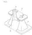
- Fig. 5 is a schematic view of a separator in the deflection unit of the present invention.
- the separator 16 has a body 22 of a substantially rectangular cross section with an aperture at one end, through which the funnel 6 of the cathode ray tube will be inserted and a small opening 26 at the other end to be located around the neck of the cathode ray tube.
- the horizontal deflection coil is positioned on the inner wall of the separator 16 and the vertical deflection coil 18 is positioned outside of the separator 16.
- the substantially rectangular cross sectional body 22 of the separator helps the horizontal and vertical deflection coils 14, 18 to be more closely located to the trajectories of the electron beams, and thus, helps to efficiently carry out the deflection of the electron beams at a wider angle with a result of reduced power consumption.
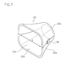
- Fig. 6 is a schematic view of a ferrite core 20 according to the present invention.
- the ferrite core 20 which is mounted on the separator 16 and the vertical deflection coil 18 is shaped similar to the separator 16.
- the ferrite core 20 has substantially flat inner and outer surfaces 20c, 20d and a large opening 20a at one end and a small opening 20b at the opposite end.
- Either the inner surface 20c alone or both of the inner surface 20c and the outer surface 20d has its cross sectional configuration gradually changing from circular at its small opening 20b to rectangular near the large opening 20a.
- the ferrite core 20 can be made in one piece as in this drawing or can be made with divided portions.
- the ferrite core 20 in Fig. 7 is formed by combining two sections, upper half and lower half, coupled along the horizontal-axis X as indicated by an arrow.
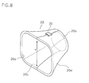
- two halves symmetrical with respect to the vertical axis Y as shown in Fig. 8 can be combined to be the ferrite core.
- the two half sections after being positioned around the separator 16, are joined to each other by using a conventional fixing means such as core clamps 30.
- Fig. 9 shows a partial cross sectional view of the cathode ray tube with respect to the tube axis, having the deflection unit mounted thereto according to the present invention.
- a phosphor screen 32 is formed inside the panel 8 and the deflection unit 10 is mounted on the cone portion 12.
- the cross section of cone portion 12 changes from circular to substantially rectangular shape from the neck to the funnel. In this way, the deflection fields generated by the deflection coils 14, 18 are formed close to the trajectories of the electron beams, and thereby, the deflection of the electron beams by the deflection unit is performed more efficiently than in prior devices.
- the vertical deflection coil 18 should be a flangeless type with no flange formed at its end to be laid on the neck side of the cathode ray tube.
- the ferrite core 20 made in two pieces should be used.
- the horizontally divided and a vertically divided ferrite core 18 have the following respective merits.
- the core clamp 30 is attached on the side walls of the outer member 20d. In this arrangement, one can easily connect the two divided sections of the ferrite core and check the connection status.
Landscapes
- Vessels, Lead-In Wires, Accessory Apparatuses For Cathode-Ray Tubes (AREA)
- Details Of Television Scanning (AREA)
- Cathode-Ray Tubes And Fluorescent Screens For Display (AREA)
- Video Image Reproduction Devices For Color Tv Systems (AREA)
Abstract
Description
- The present invention relates to a cathode ray tube, and more particularly to a cathode ray tube having a deflection unit capable of efficiently reducing power consumption.
- In a cathode ray tube, electron beams emitted from an electron gun are deflected in the horizontal and vertical directions and land on phosphors coated on a screen to display images. In particular, the electron beams are deflected by the horizontal and vertical magnetic fields generated by a deflection unit mounted on an outer surface of a funnel in a cathode ray tube.
- Such cathode ray tubes are widely used in color television and computer monitors, high definition televisions (HDTVs) and other high-tech devices.
- In order for a cathode ray tube to be suitable for applications in HDTVs or various office automation equipments, the deflection frequency should be increased and the depth of the tube should be decreased. In order to decrease the depth of the tube, an increase of the deflection power is necessary so that the cathode ray tube could deflect the electron beams at a wider angle. However, an increase in the deflection frequency and the deflection angle require increased power consumption, causing a problem of magnetic field leakage.
- In other words, in order to improve the quality of a cathode ray tube, it is essential to reduce the power consumption of the deflection unit while minimizing the magnetic field leakage.
- To this end, it was suggested that diameters of the neck and funnel of a CRT abutting the neck be reduced to promote the efficiency of the deflection. However, this cathode ray tube requires that the diameter of the electron gun be also reduced, causing a reduced resolution and unstable electron beams at high frequencies. Especially, the electron beams directed to marginal portions of the screen are likely to collide with inner wall of the funnel on the neck side, resulting in a poor image on the screen.
- To address the major problem of the suggested tube, it has been recently suggested a cathode ray tube wherein the cross section of the funnel, on which a deflection yoke is mounted, changes from circular to non-circular along the tube axis. This configuration of funnel prevents electron beams from striking the inner wall of the funnel.
- With such a funnel structure, US Patent No. 3,731,129 discloses a means for reducing a diagonal misconvergence to accomplish a wide deflection angle without increased power consumption.
- However, as long as conventional deflection units having circular cross sectional configurations are applied to these cathode ray tubes, it is difficult to actually reduce the power consumption of the deflection yoke, since the shapes of the conventional deflection units prevent the deflection units from being close to trajectories of the electron beams, and thus, do not reflect the beams power-efficiently.
- Accordingly, the present invention seeks to provide a cathode ray tube having advantages over known cathode ray tubes.
- To accomplish this, the present invention provides a deflection unit comprising a horizontal deflection coil having a non-circular cross section, a separator placed outside the horizontal deflection coil, with its inner configuration corresponding to the outer configuration of the horizontal deflection coil, a vertical deflection coil placed outside of the separator with its non-circular cross section corresponding to the outer surface of the separator, and a ferrite core for closely attaching the vertical deflection coil to the separator, with its inner side formed to be similar to the inner configuration of the vertical deflection coil.
- The invention also provides for a deflection unit for use with a cathode ray tube.
- The invention is described further hereinafter, by way of example only, with reference to the accompanying drawings in which:
- Fig. 1 is a schematic view of a cathode ray tube of the present invention along with a schematic view of a deflection unit thereof;
- Fig. 2 is a cross sectional view of the deflection unit of Fig. 1 cut along a A-A' line;
- Fig. 3 indicates a horizontal length L1 and a vertical length L2 of a vertical deflection coil of the deflection unit of the present invention;
- Fig. 4 is a graph showing a ratio of LI/L2 of the vertical deflection coil according to a distance of a coil from a funnel;
- Fig. 5 is a schematic view of a separator of the deflection unit of the present invention;
- Fig. 6 is a schematic view of a ferrite core of the deflection unit of the present invention;
- Fig. 7 is a schematic view of a modified ferrite core of the deflection unit of the present invention;
- Fig. 8 is schematic view of another ferrite core of the deflection unit of the present invention;
- Fig. 9 is a partial cross sectional view of the cathode ray tube of Fig. 1 according to the present invention with the deflection unit mounted thereto; and
- Figs. 10 and 11 are schematic views illustrating the ferrite core of the present invention connected to the vertical deflection coil according to the present invention.
-
- Fig. 1 is a schematic view of a cathode ray tube according to a preferred embodiment of the present invention. The cathode ray tube has a
cylinderical neck 4 wherein anelectron gun 2 is placed, afunnel portion 6, theneck portion 4, and apanel 8 sealed to thefunnel portion 6. - A cone portion is indicated by the
reference number 12 in the drawing, on which adeflection unit 10 Is to be mounted. The cross-sections of thecone portion 12 changes from circular to substantially rectangular as they move from the neck toward the funnel body. - Figs. 1 and 2 show a
deflection unit 10 of the present invention comprising a saddle-likehorizontal deflection coil 14 having a non-circular cross section, aseparator 16 placed outside thehorizontal deflection coil 14, having its inner configuration corresponding to the outer configuration of thehorizontal deflection coil 14, a saddle-likevertical deflection coil 18 placed outside of theseparator 16, having non-circular cross sectional form corresponding to the outer surface of theseparator 16 and aferrite core 20 for closely attaching thevertical deflection coil 18 to theseparator 16, having its inner side formed similar to the inner configuration of thevertical deflection coil 18. - The
vertical deflection coil 18 as shown in Fig. 3 has its horizontal length L1 and its vertical length L2 at a ratio of 1.0 ≤ LI/L2 ≤ 1.3, at which the power consumption of the deflection is most reduced. - The graph in Fig. 4 shows the ratio of the horizontal length L1 to the vertical length L2 of the
vertical deflection coil 18, with Z axis representing the distance from neck seal to the funnel. The deflection unit of the present invention with this ratios consumes 20% less power compared to prior devices. - When the horizontal and vertical deflection coils of the deflection unit each takes substantially rectangular shape, the horizontal and vertical fields generated by the unit also take a form similar to the substantially rectangular panel. This design makes the deflection of electron beams along the diagonals easier than in the conventional devices, and the convergence characteristic is enhanced.
- Fig. 5 is a schematic view of a separator in the deflection unit of the present invention. The
separator 16 has abody 22 of a substantially rectangular cross section with an aperture at one end, through which thefunnel 6 of the cathode ray tube will be inserted and asmall opening 26 at the other end to be located around the neck of the cathode ray tube. The horizontal deflection coil is positioned on the inner wall of theseparator 16 and thevertical deflection coil 18 is positioned outside of theseparator 16. - The substantially rectangular cross
sectional body 22 of the separator helps the horizontal andvertical deflection coils - Next, Fig. 6 is a schematic view of a
ferrite core 20 according to the present invention. Theferrite core 20 which is mounted on theseparator 16 and thevertical deflection coil 18 is shaped similar to theseparator 16. Theferrite core 20 has substantially flat inner andouter surfaces small opening 20b at the opposite end. - Either the
inner surface 20c alone or both of theinner surface 20c and theouter surface 20d has its cross sectional configuration gradually changing from circular at itssmall opening 20b to rectangular near thelarge opening 20a. - The
ferrite core 20 can be made in one piece as in this drawing or can be made with divided portions. Theferrite core 20 in Fig. 7 is formed by combining two sections, upper half and lower half, coupled along the horizontal-axis X as indicated by an arrow. In another embodiment, two halves symmetrical with respect to the vertical axis Y as shown in Fig. 8 can be combined to be the ferrite core. - The two half sections, after being positioned around the
separator 16, are joined to each other by using a conventional fixing means such ascore clamps 30. - Fig. 9 shows a partial cross sectional view of the cathode ray tube with respect to the tube axis, having the deflection unit mounted thereto according to the present invention. A
phosphor screen 32 is formed inside thepanel 8 and thedeflection unit 10 is mounted on thecone portion 12. The cross section ofcone portion 12 changes from circular to substantially rectangular shape from the neck to the funnel. In this way, the deflection fields generated by thedeflection coils - The respective merits involving the
ferrite core 20 made in one piece and the one made in separate two pieces are described below referring to Figs. 10 and 11. In the case of aferrite core 20 made in one piece as shown in Fig. 10, thevertical deflection coil 18 can be directly and easily inserted and placed into theferrite core 20. - The
vertical deflection coil 18 should be a flangeless type with no flange formed at its end to be laid on the neck side of the cathode ray tube. When the deflection coil has a flange, then, theferrite core 20 made in two pieces should be used. - The horizontally divided and a vertically divided
ferrite core 18 have the following respective merits. - That is, as for the horizontally divided
ferrite core 20 along the X-axis in Fig. 7, thecore clamp 30 is attached on the side walls of theouter member 20d. In this arrangement, one can easily connect the two divided sections of the ferrite core and check the connection status. - A vertically divided
ferrite core 20 along the Y-axis in Fig. 8, on the other hand, helps to reduce the leakage magnetic field which might be leaked through small cracks in the connecting portion of theferrite core 20. Since the cracks in the connecting portion on theferrite core 20 will not be in the way of the horizontal magnetic field produced by thehorizontal deflection coil 14 on which a high frequency is applied, there is less possibility of the leakage of magnetic field than a horizontally dived ferrite core.
Claims (6)
- A cathode ray tube comprising:a neck (4) having an electron gun (2) therein;a funnel (6) contiguous with the neck (4) and having a deflection unit attachment portion whose cross section changes from circular at one end near the neck (4) to a substantially rectangular at the other end;a deflection unit (10) mounted on the deflection unit attachment portion of the funnel, and comprising:a horizontal deflection coil (14) having a non-circular cross sectional configuration;a separator (16) disposed outside the horizontal deflection coil (14) and having an inner configuration that corresponds to the outer configuration of the horizontal deflection coil (14);a vertical deflection coil (18) disposed outside of the separator (16) and having a non-circular cross sectional configuration corresponding to the outer surface of the separator (16); anda ferrite core (20) for closely attaching the vertical deflection coil (18) to the separator (16) and having an inner surface similar to the inner configuration of the vertical deflection coil (18).
- A cathode ray tube as claimed in claim 1, wherein the ratio of the horizontal length L1 to the vertical length L2 of the vertical deflection coil (18) is 1.0≤ L1/L2≤1.3.
- A cathode ray tube as claimed in claim 1 or 2, wherein the ferrite core (20) of the deflection unit (10) is formed of at least two separate portions.
- A cathode ray tube as claimed in claim 3, wherein the at least two separate portions are symmetrical with respect to the horizontal-axis.
- A cathode ray tube as claimed in claim 3 or 4, wherein the at least two separate portions are symmetrical with respect to the vertical axis thereof.
- A cathode ray tube deflection unit comprising:a horizontal deflection coil (14) having a non-circular cross sectional configuration;a separator (16) disposed outside the horizontal deflection coil (14) and having an inner configuration that corresponds to the outer configuration of the horizontal deflection coil (14);a vertical deflection coil (18) disposed outside of the separator (16) and having a non-circular cross sectional configuration corresponding to the outer surface of the separator (16); anda ferrite core (20) for closely attaching the vertical deflection coil (18) to the separator (16) and having an inner surface similar to the inner configuration of the vertical deflection coil (18).
Applications Claiming Priority (4)
| Application Number | Priority Date | Filing Date | Title |
|---|---|---|---|
| KR9841357 | 1998-10-01 | ||
| KR1019980041357A KR100309762B1 (en) | 1998-10-01 | 1998-10-01 | Deflection yoke for cathode ray tube |
| KR1019980041618A KR100310691B1 (en) | 1998-10-02 | 1998-10-02 | Deflector and color cathode ray tube using it |
| KR9841618 | 1998-10-02 |
Publications (3)
| Publication Number | Publication Date |
|---|---|
| EP0991104A2 true EP0991104A2 (en) | 2000-04-05 |
| EP0991104A3 EP0991104A3 (en) | 2003-12-03 |
| EP0991104B1 EP0991104B1 (en) | 2006-06-14 |
Family
ID=36650883
Family Applications (1)
| Application Number | Title | Priority Date | Filing Date |
|---|---|---|---|
| EP99302484A Expired - Lifetime EP0991104B1 (en) | 1998-10-01 | 1999-03-30 | Cathode ray tube |
Country Status (8)
| Country | Link |
|---|---|
| US (1) | US20020084739A1 (en) |
| EP (1) | EP0991104B1 (en) |
| JP (1) | JP2000113832A (en) |
| CN (1) | CN1123044C (en) |
| BR (1) | BR9900943A (en) |
| DE (1) | DE69931871T2 (en) |
| MY (1) | MY130903A (en) |
| TW (1) | TW414908B (en) |
Cited By (3)
| Publication number | Priority date | Publication date | Assignee | Title |
|---|---|---|---|---|
| EP1408530A2 (en) * | 2002-10-08 | 2004-04-14 | LG. Philips Displays Korea Co., Ltd. | Cathode ray tube |
| EP1422739A2 (en) * | 2002-11-19 | 2004-05-26 | LG. Philips Displays Korea Co., Ltd. | Deflection yoke for cathode ray tube |
| US6791252B2 (en) * | 2001-03-28 | 2004-09-14 | Samsung Electric-Mechanics Co., Ltd. | Deflection yoke with quadrangular separator |
Families Citing this family (3)
| Publication number | Priority date | Publication date | Assignee | Title |
|---|---|---|---|---|
| US6943490B2 (en) * | 2002-07-11 | 2005-09-13 | Samsung Electro-Mechanics Co., Ltd. | Deflection yoke with improved deflection sensitivity |
| KR20040013916A (en) * | 2002-08-09 | 2004-02-14 | 삼성에스디아이 주식회사 | Deflection yoke for cathode ray tube |
| CN103896067A (en) * | 2012-12-27 | 2014-07-02 | 嘉兴市博宏新型建材有限公司 | Coal conveyor with belt conveying device |
Citations (2)
| Publication number | Priority date | Publication date | Assignee | Title |
|---|---|---|---|---|
| US3731129A (en) * | 1969-11-04 | 1973-05-01 | Tokyo Shibaura Electric Co | Rectangular color tube with funnel section changing from rectangular to circular |
| US5204649A (en) * | 1989-11-09 | 1993-04-20 | Mitsubishi Denki Kabushiki Kaisha | Deflection yoke |
-
1999
- 1999-03-19 JP JP11076783A patent/JP2000113832A/en active Pending
- 1999-03-29 TW TW088104938A patent/TW414908B/en not_active IP Right Cessation
- 1999-03-30 EP EP99302484A patent/EP0991104B1/en not_active Expired - Lifetime
- 1999-03-30 DE DE69931871T patent/DE69931871T2/en not_active Expired - Lifetime
- 1999-04-15 BR BR9900943-9A patent/BR9900943A/en not_active IP Right Cessation
- 1999-04-28 MY MYPI99001685A patent/MY130903A/en unknown
- 1999-05-11 CN CN99106451A patent/CN1123044C/en not_active Expired - Fee Related
-
2001
- 2001-11-20 US US09/990,140 patent/US20020084739A1/en not_active Abandoned
Patent Citations (2)
| Publication number | Priority date | Publication date | Assignee | Title |
|---|---|---|---|---|
| US3731129A (en) * | 1969-11-04 | 1973-05-01 | Tokyo Shibaura Electric Co | Rectangular color tube with funnel section changing from rectangular to circular |
| US5204649A (en) * | 1989-11-09 | 1993-04-20 | Mitsubishi Denki Kabushiki Kaisha | Deflection yoke |
Cited By (5)
| Publication number | Priority date | Publication date | Assignee | Title |
|---|---|---|---|---|
| US6791252B2 (en) * | 2001-03-28 | 2004-09-14 | Samsung Electric-Mechanics Co., Ltd. | Deflection yoke with quadrangular separator |
| EP1408530A2 (en) * | 2002-10-08 | 2004-04-14 | LG. Philips Displays Korea Co., Ltd. | Cathode ray tube |
| EP1408530A3 (en) * | 2002-10-08 | 2007-07-04 | LG. Philips Displays Korea Co., Ltd. | Cathode ray tube |
| EP1422739A2 (en) * | 2002-11-19 | 2004-05-26 | LG. Philips Displays Korea Co., Ltd. | Deflection yoke for cathode ray tube |
| EP1422739A3 (en) * | 2002-11-19 | 2009-02-25 | LG. Philips Displays Korea Co., Ltd. | Deflection yoke for cathode ray tube |
Also Published As
| Publication number | Publication date |
|---|---|
| EP0991104A3 (en) | 2003-12-03 |
| DE69931871T2 (en) | 2006-11-16 |
| JP2000113832A (en) | 2000-04-21 |
| BR9900943A (en) | 2000-05-30 |
| DE69931871D1 (en) | 2006-07-27 |
| EP0991104B1 (en) | 2006-06-14 |
| MY130903A (en) | 2007-07-31 |
| CN1250220A (en) | 2000-04-12 |
| TW414908B (en) | 2000-12-11 |
| US20020084739A1 (en) | 2002-07-04 |
| CN1123044C (en) | 2003-10-01 |
Similar Documents
| Publication | Publication Date | Title |
|---|---|---|
| TW543069B (en) | Cathode ray tube | |
| JP3403005B2 (en) | Cathode ray tube device | |
| EP0810627B1 (en) | Cathode ray tube | |
| EP0991104B1 (en) | Cathode ray tube | |
| EP0993018B1 (en) | Cathode ray tube | |
| US6380668B1 (en) | Cathode ray tube | |
| JPH10154472A (en) | Cathode-ray tube apparatus | |
| US6396204B1 (en) | Cathode ray tube with enhanced beam deflection efficiency and minimized deflection power | |
| EP0989582A1 (en) | Cathode-ray tube | |
| KR100307158B1 (en) | Cathode ray tube | |
| US6528936B1 (en) | Cathode ray tube with funnel cone thickness variations | |
| US6335588B1 (en) | Cathode ray tube | |
| KR100330147B1 (en) | Cathode ray tube | |
| US6653773B1 (en) | Cathode ray tube having enhanced electron beam deflection efficiency | |
| KR940010952B1 (en) | CRT HAVING 16í9 ASPECT RATIO | |
| US6509681B1 (en) | Deflection yoke for color cathode ray tube | |
| MXPA99004026A (en) | Cathode ray tube | |
| KR100605761B1 (en) | Cathode-ray tube | |
| US6495954B1 (en) | Cathode ray tube having reduction in deflection power consumption relative to funnel condition | |
| KR100309762B1 (en) | Deflection yoke for cathode ray tube | |
| US7501748B2 (en) | CRT funnel section | |
| US6538369B1 (en) | Cathode ray tube having particular funnel structure | |
| KR100692043B1 (en) | Cathode-ray tube | |
| JP4170791B2 (en) | Cathode ray tube | |
| KR20000073384A (en) | Cathode-ray tube |
Legal Events
| Date | Code | Title | Description |
|---|---|---|---|
| PUAI | Public reference made under article 153(3) epc to a published international application that has entered the european phase |
Free format text: ORIGINAL CODE: 0009012 |
|
| AK | Designated contracting states |
Kind code of ref document: A2 Designated state(s): AT BE CH CY DE DK ES FI FR GB GR IE IT LI LU MC NL PT SE |
|
| AX | Request for extension of the european patent |
Free format text: AL;LT;LV;MK;RO;SI |
|
| PUAL | Search report despatched |
Free format text: ORIGINAL CODE: 0009013 |
|
| AK | Designated contracting states |
Kind code of ref document: A3 Designated state(s): AT BE CH CY DE DK ES FI FR GB GR IE IT LI LU MC NL PT SE |
|
| AX | Request for extension of the european patent |
Extension state: AL LT LV MK RO SI |
|
| RIC1 | Information provided on ipc code assigned before grant |
Ipc: 7H 01J 29/76 B Ipc: 7H 01J 29/82 A |
|
| 17P | Request for examination filed |
Effective date: 20040528 |
|
| AKX | Designation fees paid |
Designated state(s): DE FR GB NL |
|
| 17Q | First examination report despatched |
Effective date: 20050504 |
|
| GRAP | Despatch of communication of intention to grant a patent |
Free format text: ORIGINAL CODE: EPIDOSNIGR1 |
|
| GRAS | Grant fee paid |
Free format text: ORIGINAL CODE: EPIDOSNIGR3 |
|
| GRAA | (expected) grant |
Free format text: ORIGINAL CODE: 0009210 |
|
| AK | Designated contracting states |
Kind code of ref document: B1 Designated state(s): DE FR GB NL |
|
| REG | Reference to a national code |
Ref country code: GB Ref legal event code: FG4D |
|
| REF | Corresponds to: |
Ref document number: 69931871 Country of ref document: DE Date of ref document: 20060727 Kind code of ref document: P |
|
| ET | Fr: translation filed | ||
| PLBE | No opposition filed within time limit |
Free format text: ORIGINAL CODE: 0009261 |
|
| STAA | Information on the status of an ep patent application or granted ep patent |
Free format text: STATUS: NO OPPOSITION FILED WITHIN TIME LIMIT |
|
| 26N | No opposition filed |
Effective date: 20070315 |
|
| PGFP | Annual fee paid to national office [announced via postgrant information from national office to epo] |
Ref country code: FR Payment date: 20100324 Year of fee payment: 12 |
|
| PGFP | Annual fee paid to national office [announced via postgrant information from national office to epo] |
Ref country code: GB Payment date: 20100322 Year of fee payment: 12 |
|
| PGFP | Annual fee paid to national office [announced via postgrant information from national office to epo] |
Ref country code: NL Payment date: 20100304 Year of fee payment: 12 Ref country code: DE Payment date: 20100430 Year of fee payment: 12 |
|
| REG | Reference to a national code |
Ref country code: NL Ref legal event code: V1 Effective date: 20111001 |
|
| GBPC | Gb: european patent ceased through non-payment of renewal fee |
Effective date: 20110330 |
|
| REG | Reference to a national code |
Ref country code: FR Ref legal event code: ST Effective date: 20111130 |
|
| PG25 | Lapsed in a contracting state [announced via postgrant information from national office to epo] |
Ref country code: FR Free format text: LAPSE BECAUSE OF NON-PAYMENT OF DUE FEES Effective date: 20110331 Ref country code: DE Free format text: LAPSE BECAUSE OF NON-PAYMENT OF DUE FEES Effective date: 20111001 Ref country code: NL Free format text: LAPSE BECAUSE OF NON-PAYMENT OF DUE FEES Effective date: 20111001 |
|
| REG | Reference to a national code |
Ref country code: DE Ref legal event code: R119 Ref document number: 69931871 Country of ref document: DE Effective date: 20111001 |
|
| PG25 | Lapsed in a contracting state [announced via postgrant information from national office to epo] |
Ref country code: GB Free format text: LAPSE BECAUSE OF NON-PAYMENT OF DUE FEES Effective date: 20110330 |