EP0990427A2 - Systeme und verfahren zum montieren eines stents auf einem katheter - Google Patents
Systeme und verfahren zum montieren eines stents auf einem katheter Download PDFInfo
- Publication number
- EP0990427A2 EP0990427A2 EP99118790A EP99118790A EP0990427A2 EP 0990427 A2 EP0990427 A2 EP 0990427A2 EP 99118790 A EP99118790 A EP 99118790A EP 99118790 A EP99118790 A EP 99118790A EP 0990427 A2 EP0990427 A2 EP 0990427A2
- Authority
- EP
- European Patent Office
- Prior art keywords
- sleeve
- catheter
- stent
- balloon
- collar
- Prior art date
- Legal status (The legal status is an assumption and is not a legal conclusion. Google has not performed a legal analysis and makes no representation as to the accuracy of the status listed.)
- Withdrawn
Links
- 238000000034 method Methods 0.000 title claims abstract description 27
- 239000000463 material Substances 0.000 claims description 17
- 239000012858 resilient material Substances 0.000 claims description 10
- 238000004519 manufacturing process Methods 0.000 claims description 2
- 230000006835 compression Effects 0.000 description 10
- 238000007906 compression Methods 0.000 description 10
- 238000002788 crimping Methods 0.000 description 6
- 230000009471 action Effects 0.000 description 4
- 238000002399 angioplasty Methods 0.000 description 4
- 210000004204 blood vessel Anatomy 0.000 description 4
- 238000011282 treatment Methods 0.000 description 4
- 230000000747 cardiac effect Effects 0.000 description 3
- 201000010099 disease Diseases 0.000 description 3
- 208000037265 diseases, disorders, signs and symptoms Diseases 0.000 description 3
- 239000004033 plastic Substances 0.000 description 3
- 239000005060 rubber Substances 0.000 description 3
- 208000031481 Pathologic Constriction Diseases 0.000 description 2
- 210000001367 artery Anatomy 0.000 description 2
- HVYWMOMLDIMFJA-DPAQBDIFSA-N cholesterol Chemical compound C1C=C2C[C@@H](O)CC[C@]2(C)[C@@H]2[C@@H]1[C@@H]1CC[C@H]([C@H](C)CCCC(C)C)[C@@]1(C)CC2 HVYWMOMLDIMFJA-DPAQBDIFSA-N 0.000 description 2
- 230000000694 effects Effects 0.000 description 2
- 239000006260 foam Substances 0.000 description 2
- 230000007246 mechanism Effects 0.000 description 2
- 230000004048 modification Effects 0.000 description 2
- 238000012986 modification Methods 0.000 description 2
- 230000008569 process Effects 0.000 description 2
- 208000037803 restenosis Diseases 0.000 description 2
- 208000037804 stenosis Diseases 0.000 description 2
- 230000036262 stenosis Effects 0.000 description 2
- 238000001356 surgical procedure Methods 0.000 description 2
- 200000000007 Arterial disease Diseases 0.000 description 1
- 208000037260 Atherosclerotic Plaque Diseases 0.000 description 1
- 229920000742 Cotton Polymers 0.000 description 1
- 241000282596 Hylobatidae Species 0.000 description 1
- HZEWFHLRYVTOIW-UHFFFAOYSA-N [Ti].[Ni] Chemical compound [Ti].[Ni] HZEWFHLRYVTOIW-UHFFFAOYSA-N 0.000 description 1
- 238000007792 addition Methods 0.000 description 1
- 230000003466 anti-cipated effect Effects 0.000 description 1
- 208000028922 artery disease Diseases 0.000 description 1
- 239000000560 biocompatible material Substances 0.000 description 1
- 235000012000 cholesterol Nutrition 0.000 description 1
- 238000007887 coronary angioplasty Methods 0.000 description 1
- 230000002939 deleterious effect Effects 0.000 description 1
- 238000002224 dissection Methods 0.000 description 1
- 239000003925 fat Substances 0.000 description 1
- 239000007943 implant Substances 0.000 description 1
- 238000002513 implantation Methods 0.000 description 1
- 229910052751 metal Inorganic materials 0.000 description 1
- 239000002184 metal Substances 0.000 description 1
- 239000000203 mixture Substances 0.000 description 1
- 238000009126 molecular therapy Methods 0.000 description 1
- 229910001000 nickel titanium Inorganic materials 0.000 description 1
- 238000006467 substitution reaction Methods 0.000 description 1
- 230000002792 vascular Effects 0.000 description 1
- 208000019553 vascular disease Diseases 0.000 description 1
- 210000005166 vasculature Anatomy 0.000 description 1
Images


Classifications
-
- A—HUMAN NECESSITIES
- A61—MEDICAL OR VETERINARY SCIENCE; HYGIENE
- A61F—FILTERS IMPLANTABLE INTO BLOOD VESSELS; PROSTHESES; DEVICES PROVIDING PATENCY TO, OR PREVENTING COLLAPSING OF, TUBULAR STRUCTURES OF THE BODY, e.g. STENTS; ORTHOPAEDIC, NURSING OR CONTRACEPTIVE DEVICES; FOMENTATION; TREATMENT OR PROTECTION OF EYES OR EARS; BANDAGES, DRESSINGS OR ABSORBENT PADS; FIRST-AID KITS
- A61F2/00—Filters implantable into blood vessels; Prostheses, i.e. artificial substitutes or replacements for parts of the body; Appliances for connecting them with the body; Devices providing patency to, or preventing collapsing of, tubular structures of the body, e.g. stents
- A61F2/95—Instruments specially adapted for placement or removal of stents or stent-grafts
- A61F2/958—Inflatable balloons for placing stents or stent-grafts
- A61F2002/9583—Means for holding the stent on the balloon, e.g. using protrusions, adhesives or an outer sleeve
Definitions
- the invention relates to systems and methods for mounting a stent onto a catheter, and more particularly, to systems and methods for maintaining a stent onto a catheter as the catheter travels through a body lumen to the site of treatment.
- PTA percutaneous transluminal angioplasty
- PTCA percutaneous transluminal coronary angioplasty
- a balloon catheter is advanced through a guide catheter so that the balloon of the balloon catheter is properly positioned within the stenosed region of the blood vessel.
- the balloon at the distal end of the catheter is inflated to widen the blood vessel at the site of the stenosis.
- re-narrowing a localized re-narrowing (restenosis) of the vessel over a period of three to six months.
- restenosis a localized re-narrowing
- a metal stent is typically deployed during the PTA or PTCA procedure to reinforce the blood vessel wall and to hold any flaps, fissures and dissections in place.
- a typical stent comprises a tubular structure that expands radially from a compact form for transit to an expanded form for implantation. Radial expansion causes the stent to implant into the tissue of a wall of the vessel being repaired or bridged to maintain its patency.
- the surgeon To place the stent at the desired site, the surgeon employs a stent delivery system that typically comprise an elongate catheter body having a transverse dimension that allows the delivery system to travel through a patient's lumens and to the desired site. Most of the existing delivery systems are provided separately from the stent which is to be placed within the patients vessel. Accordingly, the surgeon is required to mount the stent to the distal end of the delivery system. This involves the surgeon taking the stent in hand and sliding it over the distal end of the elongate catheter body.
- the surgeon slides the stent directly over the catheter body, and in the case of a balloon expandable stent, the surgeon slides the stent over a wrapped balloon that is located at the distal end of the stent delivery catheter.
- the surgeon typically pinches, or squeezes, the stent gently in order that the stent engage frictionally with the surface of the balloon. This is known as crimping.
- the point of crimping is to form the stent into an engagement with the catheter, or balloon mounted on the catheter, to cause the stent to fit snugly onto the catheter and fill any and all gaps that may exist between the stent in its predeployed condition and the catheter. It is understood that by crimping the stent onto the balloon, the surgeon minimizes the opportunity for the stent to slide off the balloon, or distal end of the catheter, as the stent is delivered through the lumen of the patient.
- the crimping process is deemed unsatisfactory. First, it requires the surgeon to actually physically deform the stent, which, although typically quite acceptable, still runs the risk of misshaping the stent to a point that may interfere with the ability of the stent to expand exactly as the surgeon had anticipated. Moreover, the frictional engagement that arises from crimping the stent onto the catheter may be insufficient to guarantee that the stent will maintain its position during delivery as the stent is guided through the body lumen.
- dams have the unfortunate effect of increasing the transverse dimension of the stent delivery system. As discussed above, it is almost always more desirable to have as small a diameter delivery system as possible, given that the delivery system is to be pushed and guided through the patients body lumen to effect delivery.
- the systems and methods described herein include stent mounting devices that have a radially expandable sleeve and a movable collar.
- a stent can fit over and sit around the periphery of the sleeve.
- the sleeve and collar can mount about the distal end of a catheter in an arrangement that allows the movable collar to slide over the catheter to push against the sleeve. Responsive to the pushing of the collar, the sleeve can radially expand from a first diameter to a second, larger diameter, thereby creating an interference fit between the sleeve and the stent, to hold the stent more tightly to the catheter delivery system.
- the device can be employed with self-expanding or mechanically expandable stents.
- the systems and methods described herein include apparatus for maintaining a stent on a catheter, comprising a sleeve formed of a longitudinally compressible material and disposed about the distal end of a catheter, the sleeve being radially expandable from a first diameter to a larger second diameter, and a collar positioned adjacent the sleeve and disposed about the exterior of the catheter, whereby moving the collar inwardly against the sleeve actuates the sleeve to expand from the first diameter to the larger second diameter.
- the sleeve can comprise a tube of resilient material, a set of bellows, including bellows having a pitch selected to create an interlocking engagement with a set of gaps in a wall of the stent, and a helical body wrapped around a portion of the catheter, including a helical body wrapped around a portion of the catheter and having a pitch selected to cause an interlocking engagement with a set of gaps in a wall of the stent.
- the collar can comprises a ring of resilient material and the sleeve and collar can be dimensionally adapted for being disposed sitting beneath the balloon of the balloon catheter.
- the system comprises a stent delivery system including a catheter, having an elongate catheter body having a proximal end and a distal end, a sleeve formed of a longitudinally compressible material and disposed about the distal end of the catheter body, the sleeve being radially expandable from a first diameter to a larger second diameter, a collar positioned adjacent the sleeve and disposed about the exterior of the catheter body and optionally, a balloon can be mounted at the distal end of the catheter body and fit over the sleeve and the collar.
- the sleeve can comprise a tube of resilient material, a bellows and or a helical body wrapped around a portion of the catheter.
- the invention includes methods for mounting a stent to a balloon of a balloon catheter, comprising the acts of providing a balloon catheter having an elongate catheter body with a balloon mounted on the catheter body, wherein the balloon is mounted over a sleeve formed of a longitudinally compressible material, and a collar positioned adjacent the sleeve and disposed about the exterior of the catheter body, fitting a stent over the balloon, and moving the collar against the sleeve to expand the sleeve from a first diameter to a larger second diameter, whereby the sleeve drives the balloon into frictional engagement with the stent.
- Similar methods are provided for mounting a self-expanding stent to a catheter of a catheter delivery system.
- the invention can be understood as a method of manufacturing a catheter comprising the acts of providing an elongate catheter body having a proximal end and a distal end, disposing a sleeve formed of a longitudinally compressible material about the distal end of the catheter body, the sleeve being radially expandable from a first diameter to a larger second diameter, disposing a collar adjacent the sleeve and about the exterior of the catheter body, and mounting a balloon mounted on the distal end of the catheter body and over the sleeve and the collar.
- the systems and methods described herein include stent mounting devices that allow for a stent to be mounted onto a catheter deliver system that will deliver the stent to the site of treatment within the patient.
- the systems and methods described herein can be employed with self-expanding stents as well as mechanically expandable stents, such as balloon stents.
- the systems of the invention include stent mounting systems that have a sleeve of resilient material that slides over the catheter body and that can be disposed at a distal end of the catheter. A collar made of resilient material can also be slid onto the catheter body and pushed up adjacent to the sleeve.
- a balloon can optionally be secured to the catheter body in a manner that sits the sleeve and collar within the interior of the balloon. In those embodiments that include self-expanding stents, no balloon is present.
- a surgeon can slide the stent over the sleeve and then move the collar into the sleeve to cause the sleeve to expand from a first diameter to a second, larger diameter.
- the sleeve diameter is sufficiently large to form a frictional interference engagement with the stent, thereby affixing the stent more securely to the catheter body. It is understood that stents so mounted are less likely to slide off the catheter during delivery through the patient's vasculature, or other body lumen.
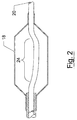
- Figure 1 shows a stent mounting system 10 that includes a sleeve 12, a collar 14, and an elongate catheter body 16, a balloon 18, and a stent 20.
- Figure 1 depicts the stent mounting system in its expanded condition, that is in a condition wherein the collar 14 has been slid into the sleeve 12 to cause the sleeve 12 to radially expand and engage the stent 20.
- the collar 14 is adjacent the distal end of the sleeve 12.
- the depicted embodiment is a stent mounting system for a balloon expandable stent.
- the collar 14 and sleeve 12 are dimensionally adapted such that both elements 12 and 14 can be disposed within the interior space defined by the balloon 18 (shown in Figure 1 in a rapt configuration).
- the stent 20 is shown as being mounted over the balloon 18 and the sleeve 12.
- the stent 20 can be manually crimped onto the catheter 16 by the manual manipulation of the surgeon as is conventionally done when securing a stent to the body of a catheter delivery system.
- the crimping step can be eliminated or minimized by further compression of the sleeve 12 by movement of the collar 14, to thereby achieve greater radial expansion of the sleeve 12.
- the depicted sleeve 12, shown in cutaway in Figure 1, can be formed as a cylindrical sleeve of resilient material that can be fitted and slid over the elongate catheter body 16.
- the sleeve 12 can be formed from a plurality of strips of resilient material that are mounted to the catheter 16 to extend laterally along a portion of the catheter, particularly that portion to which the stent 20 will be mounted.
- the sleeve 12 is secured to the catheter body 16 by affixing the proximal end of the sleeve 12 to the catheter body 16.
- the proximal end of the sleeve 12 can be epoxied to the catheter body 16 at the proximal end of the sleeve, thereby preventing the sleeve 12 from moving along the surface of the catheter 16. Moreover, by affixing the proximal end, the distal end is left free to be compressed by the action of the collar 14, thereby facilitating the radial expansion of the sleeve 12.
- the depicted sleeve 12 can be formed of any resiliant material including plastic, rubber or foam, as well as natural materials such as cotton. However, different materials can be employed for forming the sleeve 12 without departing from the scope of the invention.
- the depicted collar 14 is shown as a short collar that has a central aperture that can receive the elongate catheter body 16.
- the collar 14 is adapted to butt against the side of the sleeve 12, in order that longitudinal movement of the collar 14 will cause the compression and radial expansion of the sleeve 12.
- the collar 14 can be made of any suitable material including rubber, plastic or foam.
- the collar is designed to fit tightly about the catheter, so that the collar 14 stays in place once positioned by the surgeon.
- any suitable material can be employed for forming the collar 14 and any such modifications or substitutions are within the scope of the invention.
- Figure 2 depicts the stent mounting system 10 of Figure 1 in a condition wherein the balloon 18 is expanded.
- Figure 2 shows the stent 20 in an expanded configuration that is achieved by inflating balloon 18 to drive the stent 20 off the sleeve 12, and to expand the stent 20 for deployment within a body lumen such as a cardiac artery.
- Figure 2 depicts the collar 14 as having moved longitudinally and away from the sleeve 12. Movement of the collar 14 can occur on expansion of the balloon 18, however, it is understood that balloon 18 is not expanded until the stent 20 is placed at the location to be deployed and patency to be maintained.
- the collar 14 can be fitted sufficiently tightly over the catheter 16 such that expansion of the balloon 18 will not cause any movement of the collar 14 either distally or proximately.0
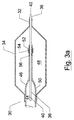
- Figure 3 depicts a further system according to the invention. Specifically, Figure 3 depicts a system 30 that includes a sleeve 32 formed as a helically wrapped body that is disposed about the periphery of catheter 38.
- the catheter 38 is a catheter for delivering a balloon expandable stent that can be opened by action of the depicted balloon 40.
- the helically wrapped sleeve 32 is fixed to the catheter 38 at a proximal location (not shown).
- sliding the collar 34 proximally causes the collar 34 to butt against and compress the helically wrapped sleeve 32; resulting in compression and radial expansion thereof.
- the radially expanding helically body can result in portions of the helical body fitting into space that occur in the side wall of the stent.
- the helical sleeve can have coils that are spaced at a pitch that is compatible with the pitch between spaces in the well of the stent 36. In this way, compression of the sleeve 32 can result in an interference fit with the spaces that occur in the wall of the stent 36.
- the depicted helical sleeve 32 can be formed of a biocompatible material that provides a spring like body that has a tendency to unwind and therefore expand radially as the coils are compressed together.
- the helical sleeve 32 can be formed of other materials, and it will be understood to one of ordinary skill of the art, that any material suitable for forming the helical sleeve 32 depicted in Figure 3 can be employed by the invention without departing from the scope thereof.
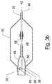
- Figure 4 depicts a further alternative embodiment of a stent mounting system according to the invention.
- Figure 4 depicts a stent mounting system 40 that includes a set of bellows 42 that act as a sleeve which fits around a portion of the catheter 44.
- a collar 48 that sits around the periphery of the catheter 44 and is disposed adjacent the bellows 42.
- the system 40 is adapted for providing a stent mounting system that can work with a balloon expandable stent such as the stent 50 that is expandable by action of the balloon 52.
- the stent 50 has an exterior wall that includes a number of spaces which are longitudinally spaced apart along the wall.
- the bellows 52 has a series of peaks such as peak 54 that, upon compression of the bellows 42, will regularly expand, and extend into the spaces 58 that occur in the stent wall 50. In this way, the compression of bellows 42 results in an interference fit with the spaces 58 in the stent 50 and provides for greater securing of the stent 50 onto the catheter 44 of the catheter delivery system.
- the bellows 42 depicted in Figure 4 can be formed of any suitable material including rubber or plastic and will be dimensionally adapted such that the compression of the bellows 42 results in the radial expansion of the bellows 42 from a first diameter to a second larger diameter, wherein that second larger diameter is sufficiently large to engage the stent 50, thereby creating either frictional engagement or an interference fit with the stent 50.
- the depicted collar 48 can be similar to any of the collars with reference Figures 1 through 3.
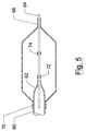
- Figure 5 depicts a further alternative embodiment of the invention wherein the depicted system 60 provides a stent mounting system for a catheter 62.
- the stent mounting system shown in Figure 5 is dimensionally adapted to fit underneath the balloon 64 and includes a collar 66 and a helically wrapped sleeve 70.
- the helically wrapped sleeve 70 has a pitch between coils that is selected to create an interference fit upon the compression of the helically wrapped sleeve 70.
- the helical sleeve 70 can expand from first diameter to a second larger diameter.
- the coils can be aligned with the spaces 72 that occur within the wall of the stent 68.
- the stent 68 is held by an interference fit that is created by the coils of the helical sleeve 70 and can extend into the spaces in 72 that occur within the wall of the stent 68.
- the systems described herein can include a plurality of collars, located both distally and proximally of the compressibly expandable sleeve.
- the systems described herein can also be employed with other stent holding devices, including sheaths and dams, as well as with mechanisms that can cause the radially expansion of the sleeve, such as mechanisms that can be controlled by the surgeon during delivery of the stent to create a radially expansive force that engages the stent and holds the stent to the delivery system.
- both the collar and sleeve can have shapes other than those shown in the depicted embodiments, and can be made of any suitable materials. Further, other embodiments can be realized, wherein the collar and the sleeve are integrally formed as a single component that can be mounted onto the catheter.
Landscapes
- Health & Medical Sciences (AREA)
- Engineering & Computer Science (AREA)
- Biomedical Technology (AREA)
- Cardiology (AREA)
- Oral & Maxillofacial Surgery (AREA)
- Transplantation (AREA)
- Heart & Thoracic Surgery (AREA)
- Vascular Medicine (AREA)
- Life Sciences & Earth Sciences (AREA)
- Animal Behavior & Ethology (AREA)
- General Health & Medical Sciences (AREA)
- Public Health (AREA)
- Veterinary Medicine (AREA)
- Media Introduction/Drainage Providing Device (AREA)
Applications Claiming Priority (2)
| Application Number | Priority Date | Filing Date | Title |
|---|---|---|---|
| US16363498A | 1998-09-30 | 1998-09-30 | |
| US163634 | 1998-09-30 |
Publications (2)
| Publication Number | Publication Date |
|---|---|
| EP0990427A2 true EP0990427A2 (de) | 2000-04-05 |
| EP0990427A3 EP0990427A3 (de) | 2000-07-05 |
Family
ID=22590882
Family Applications (1)
| Application Number | Title | Priority Date | Filing Date |
|---|---|---|---|
| EP99118790A Withdrawn EP0990427A3 (de) | 1998-09-30 | 1999-09-23 | Systeme und verfahren zum montieren eines stents auf einem katheter |
Country Status (1)
| Country | Link |
|---|---|
| EP (1) | EP0990427A3 (de) |
Cited By (5)
| Publication number | Priority date | Publication date | Assignee | Title |
|---|---|---|---|---|
| US6387118B1 (en) | 2000-04-20 | 2002-05-14 | Scimed Life Systems, Inc. | Non-crimped stent delivery system |
| US6432130B1 (en) | 2000-04-20 | 2002-08-13 | Scimed Life Systems, Inc. | Fully sheathed balloon expandable stent delivery system |
| WO2002076546A1 (en) * | 2001-03-23 | 2002-10-03 | Medtronic Ave, Inc. | Stent delivery balloon catheter and method of making same |
| US6726714B2 (en) | 2001-08-09 | 2004-04-27 | Scimed Life Systems, Inc. | Stent delivery system |
| US10583007B2 (en) | 2015-12-02 | 2020-03-10 | Edwards Lifesciences Corporation | Suture deployment of prosthetic heart valve |
Citations (1)
| Publication number | Priority date | Publication date | Assignee | Title |
|---|---|---|---|---|
| US5632760A (en) | 1994-10-20 | 1997-05-27 | Cordis Corporation | Balloon catheter for stent implantation |
Family Cites Families (1)
| Publication number | Priority date | Publication date | Assignee | Title |
|---|---|---|---|---|
| EP0932377B1 (de) * | 1996-08-23 | 2006-06-28 | Boston Scientific Scimed, Inc. | Stentanbringungssystem mit stentfixierungsvorrichtung |
-
1999
- 1999-09-23 EP EP99118790A patent/EP0990427A3/de not_active Withdrawn
Patent Citations (1)
| Publication number | Priority date | Publication date | Assignee | Title |
|---|---|---|---|---|
| US5632760A (en) | 1994-10-20 | 1997-05-27 | Cordis Corporation | Balloon catheter for stent implantation |
Cited By (8)
| Publication number | Priority date | Publication date | Assignee | Title |
|---|---|---|---|---|
| US6387118B1 (en) | 2000-04-20 | 2002-05-14 | Scimed Life Systems, Inc. | Non-crimped stent delivery system |
| US6432130B1 (en) | 2000-04-20 | 2002-08-13 | Scimed Life Systems, Inc. | Fully sheathed balloon expandable stent delivery system |
| WO2002076546A1 (en) * | 2001-03-23 | 2002-10-03 | Medtronic Ave, Inc. | Stent delivery balloon catheter and method of making same |
| US6589274B2 (en) | 2001-03-23 | 2003-07-08 | Medtronic Ave, Inc. | Stent delivery catheter and method of making same |
| US6726714B2 (en) | 2001-08-09 | 2004-04-27 | Scimed Life Systems, Inc. | Stent delivery system |
| US10583007B2 (en) | 2015-12-02 | 2020-03-10 | Edwards Lifesciences Corporation | Suture deployment of prosthetic heart valve |
| US11801138B2 (en) | 2015-12-02 | 2023-10-31 | Edwards Lifesciences Corporation | Suture deployment of prosthetic heart valve |
| US12257149B2 (en) | 2015-12-02 | 2025-03-25 | Edwards Lifesciences Corporation | Suture deployment of prosthetic heart valve |
Also Published As
| Publication number | Publication date |
|---|---|
| EP0990427A3 (de) | 2000-07-05 |
Similar Documents
| Publication | Publication Date | Title |
|---|---|---|
| US6217586B1 (en) | Catheter and method for a stent delivery system | |
| US6368344B1 (en) | Stent deployment system with reinforced inner member | |
| US6319275B1 (en) | Endolumenal prosthesis delivery assembly and method of use | |
| US6576006B2 (en) | Self-expanding stent delivery system | |
| JP4651781B2 (ja) | 自己膨張ステントデリバリー装置 | |
| US6007543A (en) | Stent delivery system with stent securement means | |
| US6315708B1 (en) | Stent with self-expanding end sections | |
| US8152819B2 (en) | Catheter support for stent delivery | |
| US5735859A (en) | Distally attachable and releasable sheath for a stent delivery system | |
| US8636707B2 (en) | Bifurcated stent delivery system | |
| US6193727B1 (en) | System for removably securing a stent on a catheter assembly and method of use | |
| EP0872220A1 (de) | Hülle und Anwendungsmethode für ein System zum Einbringen eines Stents | |
| US20020138081A1 (en) | Stent delivery system | |
| WO2000072780A1 (en) | Self-expanding stent delivery system and method of use | |
| JPH08243170A (ja) | バルーン型血管形成及びステントデリバリー用の二つの機能を有した一体型カテーテル | |
| EP0990427A2 (de) | Systeme und verfahren zum montieren eines stents auf einem katheter | |
| AU2005227406B2 (en) | Stent with self-expanding end sections |
Legal Events
| Date | Code | Title | Description |
|---|---|---|---|
| PUAI | Public reference made under article 153(3) epc to a published international application that has entered the european phase |
Free format text: ORIGINAL CODE: 0009012 |
|
| AK | Designated contracting states |
Kind code of ref document: A2 Designated state(s): AT BE CH CY DE DK ES FI FR GB GR IE IT LI LU MC NL PT SE |
|
| AX | Request for extension of the european patent |
Free format text: AL;LT;LV;MK;RO;SI |
|
| PUAL | Search report despatched |
Free format text: ORIGINAL CODE: 0009013 |
|
| RIN1 | Information on inventor provided before grant (corrected) |
Inventor name: CHOH, T. RICHARD Inventor name: MORRILL, J. RICHARD Inventor name: MOORE, TIMOTHY P. Inventor name: GILBERT, JOANNE Inventor name: FAGAN, JOHN R. |
|
| AK | Designated contracting states |
Kind code of ref document: A3 Designated state(s): AT BE CH CY DE DK ES FI FR GB GR IE IT LI LU MC NL PT SE |
|
| AX | Request for extension of the european patent |
Free format text: AL;LT;LV;MK;RO;SI |
|
| STAA | Information on the status of an ep patent application or granted ep patent |
Free format text: STATUS: THE APPLICATION HAS BEEN WITHDRAWN |
|
| 18W | Application withdrawn |
Withdrawal date: 20000810 |
|
| RIN1 | Information on inventor provided before grant (corrected) |
Inventor name: CHOH, T. RICHARD Inventor name: MORRILL, J. RICHARD Inventor name: MOORE, TIMOTHY P. Inventor name: GILBERT, JOANNE Inventor name: FAGAN, JOHN R. |