EP0990124B1 - Optical fibre bend sensor - Google Patents
Optical fibre bend sensor Download PDFInfo
- Publication number
- EP0990124B1 EP0990124B1 EP98930883A EP98930883A EP0990124B1 EP 0990124 B1 EP0990124 B1 EP 0990124B1 EP 98930883 A EP98930883 A EP 98930883A EP 98930883 A EP98930883 A EP 98930883A EP 0990124 B1 EP0990124 B1 EP 0990124B1
- Authority
- EP
- European Patent Office
- Prior art keywords
- fibre
- core
- sensor
- bend
- cores
- Prior art date
- Legal status (The legal status is an assumption and is not a legal conclusion. Google has not performed a legal analysis and makes no representation as to the accuracy of the status listed.)
- Expired - Lifetime
Links
- 239000013307 optical fiber Substances 0.000 title claims description 12
- 239000000835 fiber Substances 0.000 claims description 148
- 230000005855 radiation Effects 0.000 claims description 100
- 230000003287 optical effect Effects 0.000 claims description 93
- 230000001902 propagating effect Effects 0.000 claims description 35
- 230000008878 coupling Effects 0.000 claims description 17
- 238000010168 coupling process Methods 0.000 claims description 17
- 238000005859 coupling reaction Methods 0.000 claims description 17
- 238000004458 analytical method Methods 0.000 claims description 6
- 238000003491 array Methods 0.000 claims description 6
- 239000004038 photonic crystal Substances 0.000 claims description 5
- 238000012545 processing Methods 0.000 claims description 5
- 238000001228 spectrum Methods 0.000 claims description 5
- 230000036961 partial effect Effects 0.000 claims description 4
- 229910052691 Erbium Inorganic materials 0.000 claims description 2
- 229910052777 Praseodymium Inorganic materials 0.000 claims description 2
- UYAHIZSMUZPPFV-UHFFFAOYSA-N erbium Chemical compound [Er] UYAHIZSMUZPPFV-UHFFFAOYSA-N 0.000 claims description 2
- PUDIUYLPXJFUGB-UHFFFAOYSA-N praseodymium atom Chemical compound [Pr] PUDIUYLPXJFUGB-UHFFFAOYSA-N 0.000 claims description 2
- 230000002123 temporal effect Effects 0.000 claims description 2
- 238000005259 measurement Methods 0.000 description 23
- 238000005452 bending Methods 0.000 description 19
- 230000000694 effects Effects 0.000 description 14
- 238000000034 method Methods 0.000 description 11
- 230000008901 benefit Effects 0.000 description 7
- 230000008859 change Effects 0.000 description 7
- 238000005253 cladding Methods 0.000 description 7
- 230000005540 biological transmission Effects 0.000 description 5
- 238000001514 detection method Methods 0.000 description 5
- 238000012544 monitoring process Methods 0.000 description 5
- 239000000523 sample Substances 0.000 description 5
- 230000005291 magnetic effect Effects 0.000 description 4
- 238000010420 art technique Methods 0.000 description 3
- 239000011248 coating agent Substances 0.000 description 3
- 238000000576 coating method Methods 0.000 description 3
- 230000001419 dependent effect Effects 0.000 description 3
- 230000007613 environmental effect Effects 0.000 description 3
- 238000005305 interferometry Methods 0.000 description 3
- 238000004519 manufacturing process Methods 0.000 description 3
- 239000000463 material Substances 0.000 description 3
- 230000006835 compression Effects 0.000 description 2
- 238000007906 compression Methods 0.000 description 2
- 238000006073 displacement reaction Methods 0.000 description 2
- 230000005684 electric field Effects 0.000 description 2
- 238000000605 extraction Methods 0.000 description 2
- 238000005070 sampling Methods 0.000 description 2
- 238000000926 separation method Methods 0.000 description 2
- 241000736305 Marsilea quadrifolia Species 0.000 description 1
- VYPSYNLAJGMNEJ-UHFFFAOYSA-N Silicium dioxide Chemical compound O=[Si]=O VYPSYNLAJGMNEJ-UHFFFAOYSA-N 0.000 description 1
- 238000010521 absorption reaction Methods 0.000 description 1
- 230000006978 adaptation Effects 0.000 description 1
- 230000002730 additional effect Effects 0.000 description 1
- 230000000712 assembly Effects 0.000 description 1
- 238000000429 assembly Methods 0.000 description 1
- 230000015572 biosynthetic process Effects 0.000 description 1
- 238000004364 calculation method Methods 0.000 description 1
- 238000012512 characterization method Methods 0.000 description 1
- 230000001427 coherent effect Effects 0.000 description 1
- 230000000295 complement effect Effects 0.000 description 1
- 238000006880 cross-coupling reaction Methods 0.000 description 1
- 238000013461 design Methods 0.000 description 1
- 238000009826 distribution Methods 0.000 description 1
- 239000002019 doping agent Substances 0.000 description 1
- 230000005672 electromagnetic field Effects 0.000 description 1
- 239000005350 fused silica glass Substances 0.000 description 1
- 229910052732 germanium Inorganic materials 0.000 description 1
- GNPVGFCGXDBREM-UHFFFAOYSA-N germanium atom Chemical compound [Ge] GNPVGFCGXDBREM-UHFFFAOYSA-N 0.000 description 1
- 230000036039 immunity Effects 0.000 description 1
- 230000003993 interaction Effects 0.000 description 1
- 238000012856 packing Methods 0.000 description 1
- 230000009467 reduction Effects 0.000 description 1
- 230000035945 sensitivity Effects 0.000 description 1
- 230000003595 spectral effect Effects 0.000 description 1
- 238000003860 storage Methods 0.000 description 1
- 239000000758 substrate Substances 0.000 description 1
- 230000036962 time dependent Effects 0.000 description 1
- 238000002834 transmittance Methods 0.000 description 1
Images




Classifications
-
- G—PHYSICS
- G01—MEASURING; TESTING
- G01D—MEASURING NOT SPECIALLY ADAPTED FOR A SPECIFIC VARIABLE; ARRANGEMENTS FOR MEASURING TWO OR MORE VARIABLES NOT COVERED IN A SINGLE OTHER SUBCLASS; TARIFF METERING APPARATUS; MEASURING OR TESTING NOT OTHERWISE PROVIDED FOR
- G01D5/00—Mechanical means for transferring the output of a sensing member; Means for converting the output of a sensing member to another variable where the form or nature of the sensing member does not constrain the means for converting; Transducers not specially adapted for a specific variable
- G01D5/26—Mechanical means for transferring the output of a sensing member; Means for converting the output of a sensing member to another variable where the form or nature of the sensing member does not constrain the means for converting; Transducers not specially adapted for a specific variable characterised by optical transfer means, i.e. using infrared, visible, or ultraviolet light
- G01D5/32—Mechanical means for transferring the output of a sensing member; Means for converting the output of a sensing member to another variable where the form or nature of the sensing member does not constrain the means for converting; Transducers not specially adapted for a specific variable characterised by optical transfer means, i.e. using infrared, visible, or ultraviolet light with attenuation or whole or partial obturation of beams of light
- G01D5/34—Mechanical means for transferring the output of a sensing member; Means for converting the output of a sensing member to another variable where the form or nature of the sensing member does not constrain the means for converting; Transducers not specially adapted for a specific variable characterised by optical transfer means, i.e. using infrared, visible, or ultraviolet light with attenuation or whole or partial obturation of beams of light the beams of light being detected by photocells
- G01D5/353—Mechanical means for transferring the output of a sensing member; Means for converting the output of a sensing member to another variable where the form or nature of the sensing member does not constrain the means for converting; Transducers not specially adapted for a specific variable characterised by optical transfer means, i.e. using infrared, visible, or ultraviolet light with attenuation or whole or partial obturation of beams of light the beams of light being detected by photocells influencing the transmission properties of an optical fibre
-
- G—PHYSICS
- G01—MEASURING; TESTING
- G01M—TESTING STATIC OR DYNAMIC BALANCE OF MACHINES OR STRUCTURES; TESTING OF STRUCTURES OR APPARATUS, NOT OTHERWISE PROVIDED FOR
- G01M11/00—Testing of optical apparatus; Testing structures by optical methods not otherwise provided for
- G01M11/08—Testing mechanical properties
- G01M11/083—Testing mechanical properties by using an optical fiber in contact with the device under test [DUT]
-
- G—PHYSICS
- G01—MEASURING; TESTING
- G01D—MEASURING NOT SPECIALLY ADAPTED FOR A SPECIFIC VARIABLE; ARRANGEMENTS FOR MEASURING TWO OR MORE VARIABLES NOT COVERED IN A SINGLE OTHER SUBCLASS; TARIFF METERING APPARATUS; MEASURING OR TESTING NOT OTHERWISE PROVIDED FOR
- G01D5/00—Mechanical means for transferring the output of a sensing member; Means for converting the output of a sensing member to another variable where the form or nature of the sensing member does not constrain the means for converting; Transducers not specially adapted for a specific variable
- G01D5/26—Mechanical means for transferring the output of a sensing member; Means for converting the output of a sensing member to another variable where the form or nature of the sensing member does not constrain the means for converting; Transducers not specially adapted for a specific variable characterised by optical transfer means, i.e. using infrared, visible, or ultraviolet light
- G01D5/32—Mechanical means for transferring the output of a sensing member; Means for converting the output of a sensing member to another variable where the form or nature of the sensing member does not constrain the means for converting; Transducers not specially adapted for a specific variable characterised by optical transfer means, i.e. using infrared, visible, or ultraviolet light with attenuation or whole or partial obturation of beams of light
- G01D5/34—Mechanical means for transferring the output of a sensing member; Means for converting the output of a sensing member to another variable where the form or nature of the sensing member does not constrain the means for converting; Transducers not specially adapted for a specific variable characterised by optical transfer means, i.e. using infrared, visible, or ultraviolet light with attenuation or whole or partial obturation of beams of light the beams of light being detected by photocells
- G01D5/353—Mechanical means for transferring the output of a sensing member; Means for converting the output of a sensing member to another variable where the form or nature of the sensing member does not constrain the means for converting; Transducers not specially adapted for a specific variable characterised by optical transfer means, i.e. using infrared, visible, or ultraviolet light with attenuation or whole or partial obturation of beams of light the beams of light being detected by photocells influencing the transmission properties of an optical fibre
- G01D5/35306—Mechanical means for transferring the output of a sensing member; Means for converting the output of a sensing member to another variable where the form or nature of the sensing member does not constrain the means for converting; Transducers not specially adapted for a specific variable characterised by optical transfer means, i.e. using infrared, visible, or ultraviolet light with attenuation or whole or partial obturation of beams of light the beams of light being detected by photocells influencing the transmission properties of an optical fibre using an interferometer arrangement
-
- G—PHYSICS
- G01—MEASURING; TESTING
- G01D—MEASURING NOT SPECIALLY ADAPTED FOR A SPECIFIC VARIABLE; ARRANGEMENTS FOR MEASURING TWO OR MORE VARIABLES NOT COVERED IN A SINGLE OTHER SUBCLASS; TARIFF METERING APPARATUS; MEASURING OR TESTING NOT OTHERWISE PROVIDED FOR
- G01D5/00—Mechanical means for transferring the output of a sensing member; Means for converting the output of a sensing member to another variable where the form or nature of the sensing member does not constrain the means for converting; Transducers not specially adapted for a specific variable
- G01D5/26—Mechanical means for transferring the output of a sensing member; Means for converting the output of a sensing member to another variable where the form or nature of the sensing member does not constrain the means for converting; Transducers not specially adapted for a specific variable characterised by optical transfer means, i.e. using infrared, visible, or ultraviolet light
- G01D5/32—Mechanical means for transferring the output of a sensing member; Means for converting the output of a sensing member to another variable where the form or nature of the sensing member does not constrain the means for converting; Transducers not specially adapted for a specific variable characterised by optical transfer means, i.e. using infrared, visible, or ultraviolet light with attenuation or whole or partial obturation of beams of light
- G01D5/34—Mechanical means for transferring the output of a sensing member; Means for converting the output of a sensing member to another variable where the form or nature of the sensing member does not constrain the means for converting; Transducers not specially adapted for a specific variable characterised by optical transfer means, i.e. using infrared, visible, or ultraviolet light with attenuation or whole or partial obturation of beams of light the beams of light being detected by photocells
- G01D5/353—Mechanical means for transferring the output of a sensing member; Means for converting the output of a sensing member to another variable where the form or nature of the sensing member does not constrain the means for converting; Transducers not specially adapted for a specific variable characterised by optical transfer means, i.e. using infrared, visible, or ultraviolet light with attenuation or whole or partial obturation of beams of light the beams of light being detected by photocells influencing the transmission properties of an optical fibre
- G01D5/3537—Optical fibre sensor using a particular arrangement of the optical fibre itself
- G01D5/3538—Optical fibre sensor using a particular arrangement of the optical fibre itself using a particular type of fiber, e.g. fibre with several cores, PANDA fiber, fiber with an elliptic core or the like
Definitions
- This invention relates to an optical fibre bend sensor.
- a deformation of an optical fibre results in strain developing within the fibre. Strains can be categorised depending on the nature of the distortion which produces them.
- a longitudinal strain a one-dimensional expansion or compression of the fibre along its length, is categorised as a scalar strain.
- a scalar strain by its nature requires only one parameter, the magnitude of strain along the axis of the stretch or compression, to characterise it. In terms of the strain tensor ( ⁇ ) this longitudinal strain is the tensile component ⁇ zz .
- tensile strain ( ⁇ xx , ⁇ yy ) arises within a compressed or stretched fibre in perpendicular directions to the longitudinal strain described above. This is known as transverse strain.
- Optical fibre sensors for strain measurement are known in the prior art.
- An optical fibre is embedded in or surface-bonded to the structure to be monitored and its optical properties observed.
- the monitored structure is not limited to engineering applications e.g. aeroplane structures, building walls; optical strain sensors have been found useful in the medical field.
- a number of external influences may cause strain to develop within a structure: applied stress (elasticity) and electric field (piezoelectricity) to name two.
- An optical fibre within such a strained structure will in turn experience the effects of such strains.
- Transverse strain components will affect the refractive index and longitudinal strain components will also stretch (or compress) the fibre. In either case the optical path length of radiation propagating within the fibre is changed.
- Temperature has a similar effect to strain on an optical fibre. Thermal expansion will change the length and refractive index of the fibre and additional strains may also be induced by the differential expansion of fibre and host material. Any optical technique purporting to measure strain must make allowance for this cross-sensitivity between temperature and strain.
- a problem with prior art interferometric strain sensing techniques such as that described in patent application GB9606785.5 is that a single probe fibre measures only a scalar component of strain - the elongation of the fibre length. Transverse strain components are not measured and a general three dimensional contortion of a fibre is detectable only as a change in fibre length. Fibres have been multiplexed both in parallel and series in order to provide scalar strain measurements across a range of positions. From data gathered from an array of such single probes a map of strain gradient may be built up. However each probe intrusion inevitably weakens the structure being monitored. The interface region will be subject to increased strain and there is a clear benefit to be had in limiting the number of such interfaces.
- magnetic bearing sensors as currently used are affected by perturbations of the local magnetic field. Measurements are therefore influenced by metallic structures on the sea bed as the array passes above.
- the present invention provides a bend sensor incorporating a multicore fibre assembly having first and second component cores and being arranged to convey radiation to and from a sensor length comprising a bend sensing region of the fibre assembly and thereafter to analysing means arranged to analyse radiation output from the fibre assembly, characterised in that the fibre assembly incorporates coupling means for coupling radiation propagating from the sensor length in the first core to the second core for return to the sensor length, and reflecting means arranged to define the sensor length by at least partial reflection of radiation thereat in both cores, wherein the reflecting means and coupling means are arranged to define first and second optical paths each of which traverses the sensor length in a respective one of the cores but not the other, and the analysing means is arranged to disperse interferograms formed between radiation contributions which have traversed the optical paths.
- This invention provides the advantages of accuracy and relatively non-intrusive bend measurement.
- Optical fibre assemblies can be produced with very small diameter and embedding within a structure will thus result in minimal disruption of that structure.
- the apparatus is capable of determining bending of the sensor length, perhaps as a consequence of strain within an embedding structure, by monitoring that component of the bend in the plane of two fibre cores within the sensor length.
- Interferograms are formed between radiation propagating along two different optical paths, the optical paths differing within a specific region of the fibre. This region, the sensor length, may be only a fraction of the total fibre length. Generally, bending this sensing region will inevitably lengthen one core with respect to the other. Interrogation of this length differential by means of interferometry provides an accurate tool with which to measure bending.
- defining a sensor length down a potentially long fibre downlead enables strains to be detected at a localised region remote from the radiation input end of the fibre.
- the fibre assembly can be incorporated in, for example, a building wall, and strains developing in the deep interior of the wall measured.
- the first and second cores constitute a core pair and component cores of the multicore fibre preferably comprise an arrangement of such core pairs; and the coupling means may accordingly be arranged to couple and reflect a portion of radiation propagating in the first core into the second core of the respective core pair.
- optical path difference arising between any core pair can be interrogated, and this embodiment therefore provides a selection of planes any of which may be the plane in which components of a general bend curvature are measured.
- the sensor may also include signal processing means arranged to extract interferogram phase variation from the dispersed interferograms and to calculate bend curvature ( ⁇ ) of the sensor length from the phase variation. This provides the advantages of speed and accuracy generally to be had from signal processing power in extracting a useful parameter, bend curvature ⁇ , from interferometric data.
- respective interferograms are generated from radiation propagating within each core pair, each interferogram arising from differences in respective iirst and second optical path lengths; and the resultant calculated bend curvature ( ⁇ ) is that component of bend curvature ( ⁇ x , ⁇ y ) in a plane containing the sensor length respective core pair.
- the multicore fibre preferably comprises at least two core pairs contained in non-coincident planes, thereby enabling calculation of absolute bend magnitude and orientation from corresponding in-plane components of bend curvature.
- a single core pair can be used to obtain a measurement only of a general three dimensional curvature projected onto a specific plane: that of the core pair.
- measurement of two non-coplanar projections by means of two non-coplanar core pairs, enables both the degree of curvature and the orientation of the plane of the curve to be deduced.
- the two non-coplanar core pairs are contained in orthogonal planes. This maximises the likelihood of an accurate measurement of any bend direction within a general three-dimensional volume. If more than two core pairs are used to measure multiple projections of a single curvature, magnitude and orientation determination can be made with increased accuracy.
- the cores within each pair have unequal effective refractive indices. This enables bend "handedness" to be determined in cases for which it is ambiguous. Although bend magnitude can be determined using a single core pair of equal refractive index, such an arrangement cannot distinguish between a bend to the right and a bend to the left i.e. there is no indication of which particular core of the pair is compressed, However, by arranging for the cores to be distinguishable in terms of optical path length, a means for determining which of the pair is compressed is provided. The optical path difference measured by this embodiment of the invention is now dependent on the direction of the bend.
- the multicored fibre is preferably a bunched multiple monomode (BMM) fibre.
- BMM bunched multiple monomode
- Such fibres are known and comprise multiple fibre cores, each with an associated cladding "region".
- Each cladding region is smaller in cross-sectional area than would be required for typical cladding of cylindrical symmetry. This enables the cores to be more closely spaced than previously permitted, with regard to the requirements for avoiding crosstalk. This in turn results in an overall reduction of the diameter of a multicore cable. This is advantageous to many applications of bend sensing in which it is desirable to minimise the disruption to a structure under observation by intrusion of a probe.
- the component cores may be stress-induced highly birefringent (HiBi) cores. This provides the sensor with the capability of discriminating between the effects of temperature and strain.
- HiBi stress-induced highly birefringent
- the multicored fibre may be a photonic crystal fibre. This again provides the advantage of compactness.
- a photonic crystal fibre is another example of a multicored fibre in which crosstalk can be kept to an acceptable level, but overall fibre diameter is reduced in relation to a traditionally structured fibre bundle.
- the fibre assembly is arranged to receive incident broadband radiation and the analysing means is arranged to form a channelled spectrum by dispersing interferograms formed between radiation propagating in the first and second optical paths as a function of wavelength.
- Suitable broadband radiation may be provided by a superluminescent diode, an Erbium Doped Fibre Amplifier or a Praseodymium light source. These sources do not all operate over the same wavelength range and appropriate detectors need to be used in each case.
- Interferometric techniques rely on measuring changes across the interference pattern as a function of the phase of the radiation forming it. It is therefore necessary to scan across a range of phase angles. Commonly optical path difference is scanned, although an equivalent phase scan may be achieved by scanning radiation wavelength.
- this embodiment of the invention scans radiation wavelength at constant optical path difference.
- the principal advantage of this implementation is that it requires neither an external reference path nor any motion of the sensing length, which would be impracticable in many applications, to compensate for the optical path difference introduced by the bend. This reduces the ancillary apparatus required to interrogate the sensing fibre once it has been embedded in a structure.
- the senor may also include a scanning interferometer arranged to perform a scan of optical path lengths defined within and whereby interferometer optical path differences compensate for the optical path difference between first and second optical paths and the analysing means is arranged to disperse interferograms formed between radiation propagating in the first and second optical paths as a function the interferometer scan.
- the interferometer may be arranged to perform either a spatial or temporal scan.
- the component cores may be distributed in a symmetrical arrangement within the multicore fibre.
- the fibre is preferably less than 130 ⁇ m in diameter.
- the coupling means is preferably a tandem coupler.
- a tandem coupler is an optical element which reflects a proportion of the radiation incident on it from one direction, transmits another proportion and at the same time couples the reflected radiation into another fibre core.
- the tandem coupler preferably incorporates a beamsplitter wherein the beamsplitter comprises a base and, non-coplanar with this, respective pairs of planar surface faces for each core pair wherein each planar surface face extends from the base towards an apex and faces within each pair are mutually disposed at approximate right angles.
- a beamsplitter conveniently provides in a single component the reflection and transmission characteristics required for the functioning of the tandem coupler.
- the multicored fibre may have four symmetrically oriented component cores and the beamsplitter may comprise a square base, four triangular surface faces and an apex wherein each triangular face extends from one side of the square base to the apex and the perpendicular distance from the apex to the base is one half of the distance of one side of the base.
- the beamsplitter may comprise a square base, four triangular surface faces and an apex wherein each triangular face extends from one side of the square base to the apex and the perpendicular distance from the apex to the base is one half of the distance of one side of the base.
- the beamsplitter may be located intermediate to first and second planar microlens arrays wherein each microlens array includes a respective microlens located a focal distance away from each component core and wherein the microlenses of each array are arranged in a common plane and the common planes of each lens array are mutually parallel and parallel to the base of the beamsplitter.
- the microlenses in these arrays thus either produce a collimated beam from radiation exiting the cores, or couple collimated radiation into the fibre cores. This aids operation of the tandem coupler.
- a further aspect of the invention provides a temperature sensor incorporating a multicore fibre assembly having first and second component cores and being arranged to convey radiation to and from a sensor length comprising a bend sensing region of the fibre assembly and thereafter to analysing means arranged to analyse radiation output from the fibre assembly, characterised in that the fibre assembly incorporates coupling means for coupling radiation propagating from the sensor length in the first core to the second core for return to the sensor length, and reflecting means arranged to define the sensor length by at least partial reflection of radiation thereat in both cores, wherein the reflecting means and coupling means are arranged to define first and second optical paths each of which traverses the sensor length in a respective one of the cores but not the other, and the analysing means is arranged to disperse interferograms formed between radiation contributions which have traversed the optical paths.
- this invention provides a beamsplitter comprising a base and non-coplanar therewith respective pairs of planar reflecting faces each extending from the base towards an apex, faces within each pair being mutually disposed at least approximately at right angles to one another.
- the beamsplitter may be arranged to reflect radiation propagating in a first core of a multicored fibre into a second core thereof, the cores comprising an opposite core pair aligned with a respective pair of reflecting faces such that an optical path exists from the first core to the second core via reflections from the reflecting faces.
- the multicored fibre has four symmetrically oriented component cores and the beamsplitter has a square base, four triangular surface faces and an apex wherein each triangular face extends from one side of the square base to the apex and the perpendicular distance from the apex to the base is one half of the length of one side of the base,
- a tandem coupler may incorporate a beamsplitter in accordance with the above description located intermediate to first and second planar microlens arrays wherein each microlens array includes a respective microlens located a focal distance away from each component core and wherein the microlenses of each array are arranged in a common plane and the common planes of each lens array are mutually parallel and parallel to the base of the beamsplitter.
- a tandem coupler has many applications in devices in which it is required to define an optical path encompassing two fibre cores.
- an optical fibre bend sensor of the invention for making vector strain measurements is illustrated generally by 10.
- the sensor 10 incorporates a pair of fibre pigtailed superluminescent diodes 12, 14 connected to a respective pair of input monomode optical fibres 16, 18.
- Superluminescent diodes are particularly intense sources of broadband radiation.
- Suitable diodes 12, 14 for use in this invention are supplied by Superlum Ltd., SLD-361/A-TO-SM, with wavelength range centred at 825 nm and FWHM bandwidth of 18 nm.
- the input monomode fibres 16, 18 and two output monomode fibres 20, 22 are connected via a fan-out connector 24 to respective cores of a 4-core Bunched Multiple Monomode (BMM) fibre assembly 26.
- BMM Bunched Multiple Monomode
- Each output monomode fibre 20, 22 is also connected at its opposite end to a fibre optic linked spectrometer 27a, 27b. Both fan-out connectors and BMM fibres are known and described in Opto and Laser Europe, issue 23, p29 (September 1995).
- the BMM fibre assembly 26 comprises a tandem coupler 28; three 4-core BMM fibres: a first length 30, sensor downlead 32 and sensor length 34; a semi-reflective splice 36 through the fibre assembly 26; and a silvered mirror 38 coating the fibre assembly 26 end.
- the cores of the first length 30 of BMM fibre are those connecting the assembly to the fan-out connector 24. At their opposite ends the first length 30 cores are optically connected to the tandem coupler 28.
- the sensor downlead 32 is the fibre section of the assembly 26 extending from the tandem coupler 28 to the semi-reflective splice 36 and the sensor length 34 extends thereafter to the silvered mirror 38 coating the fibre end.
- the sensor length 34 corresponds to a fibre of length L s at the extreme end of the fibre assembly, distant from the input connections.
- Enlarged views 40, 42 are shown of the 4-core BMM fibre assembly 26 at the semi-reflective splice 36 and the mirrored end 38 locations 44, 46.
- the splice 36 and mirrored end 38 exhibit negligible absorption and have reflectances of approximately 1 / 3 and 1 respectively.
- the BMM fibre assembly 26 is flexible and fashionable into a variety of conformations.
- bending of the sensor length 34 occurs with respect to a pivot point 48 located at the centre of the fibre at the position 44 of the splice 36. Any bending of the sensor length 34 about this pivot 48 is resolvable into components of curvature 50, 52 in two mutually perpendicular planes, each component having a respective radius of curvature R x , R y (not illustrated). The orientation of these components 50, 52 with respect to the BMM fibre cores will be described later.
- a cross section of BMM fibre along AA' of Figure 1 is illustrated in Figure 2 and indicated generally by 60.
- the fibre comprises first and second input 62, 64 and first and second output 66, 68 monomode cores embedded within a lower refractive index cladding 70.
- a dashed circle 72 with diameter equal to the maximum width of the BMM fibre illustrates the spatial extent of the fibre cross-section.
- the four cores 62, 64, 66, 68 are symmetrically oriented with nearest-neighbour spacing 74 of 44.2 ⁇ m.
- Opposite input/output core pairs 62, 66 and 64, 68 have an intrapair separation 76 of 62.5 ⁇ m.
- the cladding material is fused silica and core refractive index profiles are defined within by germanium (Ge) doping. Two slightly different levels of Ge dopant are used to form the cores.
- the input cores 62, 64 therefore have slightly different refractive index profiles in comparison with the output cores 66, 68.
- the four cores 62, 64, 66, 68 and cladding 70 are in a symmetrical four leaf clover arrangement with maximum diameter 78 of 125 ⁇ m. This core arrangement applies to the three fibre sections of the fibre assembly 26.
- cores within the first length 30 are referenced with an additional symbol "a"
- corresponding cores within the sensor downlead 32 are referenced with an additional "b”
- those within the sensor length 34 are referenced with an additional "c” e.g. 62c, 64c, etc.
- Figures 3 and 5 are both illustrations at various sections of the fibre assembly 26 in a plane containing BB' which passes through one of the two opposite core pairs 62, 66.
- Figure 3 is a view in the plane of the first opposite core pair 62, 66 illustrating the structure of the tandem coupler 28.
- the core pair 62, 66 comprises input 62 and output 66 cores.
- the tandem coupler 28 is similarly structured in the plane (not illustrated) of the second core pair 64, 68 and performs the same coupling function with regard to radiation propagating within these cores 64, 68. Components referred to previously are like referenced in this Figure. Specifically the tandem coupler is situated intermediate the first length cores 62a, 64a, 66a, 68a and the sensor downlead cores 62b, 64b, 66b, 68b.
- Each first length core 62a, 66a shares an optic axis 80, 82 with the corresponding sensor downlead core 62b, 66b.
- First 80 and second 82 optic axes of respective cores 62, 66 are illustrated in relation to the tandem coupler structure.
- the tandem coupler 28 comprises first 84 and second 86 Distributed Index - Planar MicroLens arrays (DI-PMLs) sandwiching a pyramid beamsplitter 88.
- DI-PMLs Distributed Index - Planar MicroLens arrays
- the input core optic axis 80 is aligned with first 90 and second 92 microienses, the first microlens 90 being part of the first DI-PML 84 and the second microlens 92 being part of the second DI-PML 86.
- the output core optic axis 82 is aligned with third 94 and fourth 96 microlenses, these again being respective components of the first 84 and second 86 DI-PML.
- Each microlens 90, 92, 94, 96 is one focal length distant from respective first, second, third and fourth end faces 98, 100, 102, 104 of the cores 62a, 62b, 66a, 66b.
- the refractive index of the DI-PML substrate material is nominally matched to that of the BMM fibre cores 62, 66.
- the pyramid beamsplitter 88 has mutually perpendicular first 106 and second 108 semi-reflective plane surfaces aligned at 45° to respective optic axes 80, 82.
- This orientation of beamsplitter surfaces 106, 108 has particular effect on radiation exiting from the downlead core pair 62b, 66b and incident on the pyramid beamsplitter 88 from the direction of the sensor downlead. A fraction of such radiation is switched into the opposite core within the downlead core pair 62b, 66b and its propagation direction reversed.
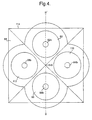
- FIG 4 is a schematic illustration of the pyramid beamsplitter 88 viewed through the tandem coupler 28 towards the sensor downlead 32.
- sensor downlead cores 62b, 64b, 66b, 68b are surmounted by respective microlenses 92, 110, 96, 112 of diameter 40 ⁇ m.
- the pyramid beamsplitter 88 is sited above these microlenses 92, 110, 96, 112.
- the beamsplitter 88 is a pyramid structure with square base 114 with sides 108 ⁇ m in length and apex 116 sited above at a perpendicular height 54 ⁇ m. This defines four planar triangular side faces, each inclined at an angle of 45° to the exit faces of respective cores.
- Figure 5 is a schematic illustration of possible optical paths within the opposite core pair 62, 66 and through intermediate optical components 28, 36.
- Light propagating within the second core pair 64, 68 follows similarly arranged paths but rotated through an angle of 90° about an in-plane axis along the length of the BMM fibre assembly 26.
- Components in this Figure which are also illustrated in previously described Figures are referenced as before. Such components include the tandem coupler 28, sensor downlead 32 and length 34, semi-reflective splice 36 and the silvered mirror end 38.
- a bend axis 120 through the pivot 48 and parallel to the length of the BMM fibre assembly 26 provides a reference axis with respect to which a general bend of the sensor length 34 is defined.
- a bend is resolved into two components of curvature 50, 52.
- One component 50 has a radius of curvature R x and is contained within the plane of the first opposite core pair 62c, 66c.
- a second component 52 (not illustrated) has a radius of curvature R y and is contained within the plane of the second opposite core pair 64c, 68c.
- Two optical paths within the system are illustrated: a first 122 corresponding to that taken by radiation which is transmitted by the splice 36 while propagating within the input cores 62b, 62c and reflected by the splice while propagating in the output cores 66b, 66c, and a second 124 corresponding to that followed by radiation reflected by the splice 36 in the input cores 62b, 62c and transmitted by it in the output cores 66b, 66c.
- the mode of operation of the bend sensor 10 of the invention is as follows.
- the device 10 is capable of measuring strain at the sensor length 34 which results in a displacement bending of this length 34.
- Broadband radiation from each SLD 12, 14 is coupled into a respective one of the pair of input monomode optical fibres 16, 18. Radiation propagates within these optical fibres 16, 18 and is coupled by the fan-out connector 24 into two nearest-neighbour cores 62a, 64a of the four core BMM fibre assembly 26.
- Radiation propagation continues along the first length cores 62a, 64a, through the tandem coupler 28 and then within corresponding nearest-neighbour cores 62b, 64b of the sensor downlead 32 to the semi-reflective splice 36.
- a first component of the radiation is transmitted along the sensor length 34 to the silvered mirror 38 coating the fibre end. This component of radiation is then reflected by the mirror 38 and returned through the splice 36 to the tandem coupler 28.
- a second component of radiation is reflected from the splice 36 directly back along the sensor downlead 32 to the tandem coupler 28.
- the tandem coupler 28 is arranged to transmit a first fraction of the radiation incident on it from the sensor downlead 32 and reflect a second fraction.
- the first fraction is transmitted to the first length 30 of the BMM fibre assembly 26, maintaining waveguide core occupancy. That is, radiation within one core 62b, 64b of the sensor downiead 32 is transmitted to the corresponding core 62a, 64a of the first length 30.
- the second fraction is coupled into the second (output) core 66b, 68b of each respective opposite core pair 62b, 66b; 64b, 68b and reflected back along the sensor downlead 32.
- This reflected fraction thus executes a second pass through the sensor downlead 32 and sensor length 34 sections of the BMM fibre assembly 26, this time following similarly structured optical paths but confined to different cores.
- On its subsequent return to the tandem coupler 28, a portion of this reflected fraction is transmitted through the tandem coupler 28, maintaining waveguide core 66, 68 occupancy.
- This is the fraction of incident radiation which contains information about the various optical path lengths within the cores of the BMM fibre assembly 26 which are of interest to this invention. A detailed description of the information contained and its extraction by interferometry will be provided later.
- Radiation propagating from the tandem coupler 28 in the output cores 66a, 68a of the BMM fibre assembly 26 is coupled by the fan-out connector 24 into respective output monomode fibres 20, 22. Radiation output from each monomode fibre 20, 22 is analysed by a respective fibre optic linked spectrometer 27a, 27b.
- Core separation 74 and dimensions, and cladding dimensions 76 are such as to avoid significant crosstalk between radiation propagating in each core 62, 64, 66, 68 and yet maintain an acceptably small fibre diameter 78 overall.
- An external diameter of 125 ⁇ m lends itself to a number of applications in which the disturbance caused by sensor intrusion should be minimised.
- the operation of the tandem coupler 28 is as follows. This description refers only to radiation propagating within the first opposite core pair 62, 66, Radiation also propagates in the second opposite core pair 64, 68 in a symmetrically equivalent arrangement. However there is minimal interaction of radiation between the two pairs and for reasons of brevity only the first core pair 62, 66 is referred to. Nonetheless, the complete embodiment of this invention does include a symmetrically equivalent arrangement in a plane perpendicular to that of the first core pair 62, 66 parallel to the BMM fibre axis.
- Radiation propagating in input core 62 is reflected from the splice 36 and/or the mirrored end 38 and directed back along the sensor downlead 32 towards the tandem coupler 28.
- This radiation is substantially contained within one core 62b of the opposite pair 62b, 66b and is incident on the tandem coupler 28 at the fibre end face 100.
- Radiation is collimated by the second microlens 92 of the second DI-PML 86 and directed towards the first semi-reflective plane surface 106 of the pyramid beamsplitter 88.
- One component of this radiation is transmitted to the first microlens 90 of the first DI-PML 84 and the second component is reflected towards the second semi-reflective plane surface 108 of the pyramid beamsplitter 88.
- the principle behind the operation of this invention is outlined. As before, the description is limited only to propagation along the first opposite core pair 62, 66 although symmetrical optical paths are followed in a perpendicular plane. Radiation enters the system propagating along the first length 30 within the input core 62a of the first opposite core pair 62a, 66a. It is transmitted through the tandem coupler 28, propagates along the sensor downlead 32 in input core 62b to the splice 36. There are two optical paths 122, 124 through the system containing information pertinent to this invention and they diverge at this point. The first optical path 122 is that followed by radiation transmitted by the splice 36.
- This component propagates in input core 62c to the mirrored end 38 where it is reflected and propagates back to the splice 36.
- the second optical path 124 is that followed by radiation reflected when first incident on the splice 36. Both components therefore propagate from the splice 36 back along the sensor downlead 32 in input core 62b again following a common path. On reaching the tandem coupler 28, both components are reflected and coupled into the output core 66b of the core pair 62b, 66b. Still following a common path, the components propagate for a third time along the sensor downlead 32, on this occasion confined to a different core 66b, 66c. At the splice 36 the optical paths 122, 124 again diverge.
- the first optical path 122 is followed by radiation reflected at the splice 36 and the second optical path 124 is followed by transmitted radiation.
- the component of radiation following this second optical path 124 is reflected by the mirrored end 38 and returned to the splice 36.
- Propagating from the splice 36, back towards the tandem coupler 28 the components again follow a common path. They are both transmitted by the tandem coupler 28 and exit the system confined in the output core 66a. Radiation output from the system in this core 66a is subject to interferometric analysis by the fibre optic linked spectrometer 27a.
- the difference therefore between these two optical paths 122, 124 is that the first 122 requires two passes of the sensor length 34 in the input core 62c and the second 124 requires these passes to be made in the output core 66c.
- a bending of the sensor length 34 inevitably results in a lengthening of one core with respect to the other of the pair 62c, 66c.
- the features of an interference pattern generated from radiation following the first optical path 122 and radiation following the second optical path 124 is dependent on the optical path difference (OPD) between the two paths 122, 124.
- OPD optical path difference
- This OPD is therefore indicative of the degree of bending of the sensor length 34 in the plane of the opposite core pair 62c, 66c.
- Two perpendicular components of a sensor length bend are measured in this embodiment of the invention - one in each plane defined by an opposite core pair. From this data the degree and orientation of the bend is deduced. Because the refractive index of the input core 62c is slightly different from that of the output core 66c, the OPD is dependent on the direction of a bend i.e. whether the input core 62c is compressed or stressed with respect to output core 66c. Thus bend handedness is also measured by this invention.
- Figure 6 is a representation of the effect of bending the sensor length 34. Bending is illustrated as being in the plane of Figure 5 i.e. this Figure is a section through the sensor length 34 in the plane of the first opposite core pair 62c, 66c. The bend is described in terms of its radius of curvature R x .
- a central axis 130 of the sensor length 34 provides a reference length ( L s ) and a reference strain which is taken to be zero.
- L s reference length
- the input core 62c is compressed and experiences a strain of - ⁇ A and the output core 66c is stretched to a strain + ⁇ B .
- the cores 62c, 66c are located a distance rfrom the central axis 130.
- FIG. 2 is an illustration of the component in the plane of a cross-section taken along BB' in Figure 2 .
- Optical elements within the fibre assembly are arranged such that radiation propagating in one core 62, 64 of each component plane is coupled into the other core 66, 68 within that same component plane.
- any optical path difference between the two cores 62, 66 arising from a general fibre bend is evidenced in an interference pattern formed from radiation components traversing different paths.
- This interference pattern is used to extract the sensor length bend component within the plane defined by the coupled cores. Defining the component planes by well-separated cores is advantageous because of the increased optical path length differential resulting from a bend.
- the sensor length bend component in the plane defined by coupled cores 62, 66 has general radius of curvature R x .
- the central axis 130 of the sensor length 34 provides a reference length and strain of zero relative to which the strain at each core is measured. In this embodiment of the invention any tensile strain and resultant change in the overall fibre sensor length L s is not detected. Changing L s will affect both optical paths 122, 124 equally and, although therefore this parameter is not constant, its variation is irrelevant to the analysis below.
- longitudinal strain may be measured by a prior art technique, if required, although it is not necessary for many applications envisaged.
- prior art techniques such as patent application PCT/GB94/01388 to measure longitudinal strain require interrogation of a sensor length against an external reference. It is an advantage of this invention that an external reference is not needed either to provide a complementary path difference or to facilitate scanning of an optical path difference, which cannot be achieved within the sensor length.
- an external reference is incorporated, it is a simple extension of a prior art technique to interrogate each core of a multicore fibre independently, derive values of longitudinal strain at each core and thereby determine bend magnitude and orientation. It is to be appreciated that, as already part of the prior art, longitudinal strain measurement is not central to the inventive concept behind this invention and will be omitted from this description for clarity.
- the parameter K is a strain-optic coefficient which is given by where p 11 , p 12 are Pockels coefficients and ⁇ is Poisson's ratio.
- Equation (1) therefore describes mathematically the phase of radiation as it propagates within a monomode waveguide core.
- Radiation input to the system and propagating down first input core 62 can be represented at time t by the analytic signal where E is the radiation instantaneous electric field, ⁇ the angular frequency, z the distance travelled along the guide core, ⁇ 0 the initial phase and ⁇ the phase variation with distance.
- E the radiation instantaneous electric field
- ⁇ the angular frequency
- z the distance travelled along the guide core
- ⁇ 0 initial phase
- ⁇ the phase variation with distance.
- OPL is the optical path length traversed
- ⁇ core the effective refractive index of the fibre core and c the speed of light.
- Radiation transmitted for a first time through the tandem coupler 28 propagates along the first input core 62b to the splice 36 where it is split into two components.
- the first component (indicated by subscript T ), following the first optical path 122, is transmitted by the splice 36 and then reflected at the mirrored end 38.
- the second component (indicated by subscript R ), following the second optical path 124, is simply reflected.
- the splice 36 transmits and reflects incident radiation with transmission and reflection coefficients ⁇ s and ⁇ s respectively and the mirrored end 38 reflects with reflection coefficient ⁇ m .
- any phase change experienced by all radiation components as a result of traversing a common path will be referred to generically as ⁇ cp .
- E R ⁇ s ⁇ tc E 0 e i ⁇ cp
- E T ⁇ 2 s ⁇ m ⁇ tc E 0 e i ⁇ cp e i ⁇ A
- the common time-dependent term e i ⁇ t is not shown and initial phase ⁇ 0 has been incorporated into ⁇ cp .
- the factor of ⁇ tc arises from the first pass through the tandem coupler 28.
- the phase ⁇ A is the additional phase change developed in the transmitted component due to the optical path length associated with two passages (one in each direction) through the sensor length 34 in the input core 62c. This optical path length is given by 2L s62 ⁇ core62 .
- the radiation components of interest to this invention are those which are then reflected into the output core 66b, experiencing a reflection coefficient ⁇ tc .
- these components propagate to and are incident on the splice 36 for the first time in the output core 66b.
- each component is split into a further two components: one ( R ) is simply reflected by the splice 36; the other ( T ) is transmitted by the splice 36, reflected by the mirrored end 38 and then again transmitted through the splice 36.
- E RR ⁇ tc ⁇ 2 s ⁇ tc E 0 e i ⁇ cp
- E TR ⁇ tc ⁇ s ⁇ 2 s ⁇ m ⁇ tc E 0 e i ⁇ cp e i ⁇
- a E RT ⁇ tc ⁇ 2 s ⁇ m ⁇ s ⁇ tc E 0 e i ⁇ cp e i ⁇ B
- E TT ⁇ tc ⁇ 4 s ⁇ 2 m ⁇ tc E 0 e i ⁇ cp e i ⁇ A e i ⁇ B
- ⁇ B is the phase difference introduced by traversal of the optical path between the splice 36 and mirrored end 38 within the output core 66c. Since two passages of the sensor length 34 are made, this optical path length is given by 2
- the total output signal can be represented by a supposition of four fields:
- This signal is input to the fibre optic linked spectrometer 27a.
- Information concerning the bend of the sensor length, as described in Equation (1), is contained within the phases of the four components of Equation (2). This is extracted using interference techniques. Formation of a coherent interference pattern is governed by the mutual phase difference between the four components and their subsequent detection optical bandwidth.
- This embodiment of the invention is arranged such that the effective coherence length on detection is less than twice the sensor length ( L s ) but greater than the largest difference in optical path length at the extremity of bend curvature. In this way the first and fourth components of Equation (2) do not interfere with any other component and the second and third components interfere on detection throughout a full range of practical bend curvatures.
- the fibre optic linked spectrometer 27a incorporates an array of pixel detector elements.
- the restriction on optical bandwidth per pixel of the detector array is subject to the condition: where OPL is the optical path length and subscripts SA and SB refer to propagation through the sensor length 34 in input 62c and output 66c cores respectively. In the embodiment herein described, this condition is satisfied by the commercially available Ocean Optics PC1000 fibre-linked spectrometer.
- Second order terms in ⁇ are at least four orders of magnitude less than first order terms and, to a very good approximation, can be neglected.
- the resultant phase difference arising from a bend curvature ⁇ is thus: and the generated interferogram has intensity variation I out ( L s , ⁇ , ⁇ ) ⁇ 2.05 + cos ⁇ ( L s , ⁇ , ⁇ )
- the slightly different doping levels in the input 62c and output 66c cores enables the direction of bend curvature within this plane, i.e. whether input core 62c is compressed or extended, to be determined.
- Different doping levels ensure that ⁇ A ( ⁇ ) ⁇ ⁇ B ( ⁇ ), ⁇ ( L s , ⁇ , ⁇ ) ⁇ - ⁇ ( L s ,- ⁇ , ⁇ ) and so I out ( L s , ⁇ , ⁇ ) ⁇ I out ( L s ,- ⁇ , ⁇ ). If ⁇ A > ⁇ B , a positive curvature ( ⁇ ) will result in an expanded fringe system in comparison with a negative curvature.
- the system 10 is calibrated initially over a range of both positive and negative bend curvatures and it may become apparent at this stage that the frequency ranges of cosine fringes in the two regimes do not overlap.
- the superiuminescent diodes 12, 14 inject broadband radiation into the system 10 and broadband interferograms are generated. These interferograms are detected using the fibre optic linked spectrometers 27a, 27b. In the plane defined by core pair 62, 66, radiation output from the end of the BMM fibre assembly 26 is dispersed and focused by the spectrometer 27a onto a linear detector array as a channelled spectrum. In this way one point (constant optical path difference) of the interferogram is sampled over a range of wavelengths.
- Another sampling technique which provides alternative embodiments of the invention derives from scanning the sensor length L s . However scanning sensor length presents additional considerations which may not be acceptable in some applications.
- Interferograms may be produced either spatially or temporally. Spatial multiplexing of an interferogram allows for the possibility of fringe tracking. This involves continuous monitoring of a portion of the interferogram the motion of which is attributable to changes in the bend curvature of a sensing element. This constitutes a convenient monitoring technique which presents readily interpretable results, without the need for complex signal processing.
- the interferogram is sampled as a function of ⁇ by the spectrometer 27a.
- the sampling is discrete (at the position of each pixel of the detector) and results in a series of interferogram intensities measured at each pixel position.
- the detector has substantially identical pixels whose positions in the array increment linearly with wavelength.
- the measured channelled spectrum function is termed I ( p i ) where p i represents the position of the i th pixel.
- a Fourier transform of this function is calculated to give the function I ( q i ) , where q i represents inverse pixel position (spatial frequency). Noise within the system appears at the high frequency end of this I ( q i ) spectrum.
- ⁇ ( p i ) For each component sampled along the detector array a value of ⁇ ( p i ) is calculated from the argument of the analytic signal I'( p i ).
- the phase is unwrapped to remove 2 ⁇ discontinuities and a series of phase values across pixel positions are obtained.
- the wavelength variation across the broadband source output is approximately from 810nm to 840nm i.e. ⁇ 3.64%.
- the inverse wavelength range is therefore to a first order approximation, also broadly linear and no significant error will arise in taking pixel position to represent inverse wavelength. In fact this error is reduced still further by the bandpass filter which removes higher order components of the expansion.
- This phase variation can then be fitted to a polynomial. For the purpose of bend curvature a first order least-squares fit will generally be sufficient.
- the bend curvature ( ⁇ x ) may be extracted from the phase variation with inverse wavelength using Equation (4) above.
- the other parameters of Equation (4): ⁇ A ( ⁇ ), ⁇ B ( ⁇ ), r , K , and L s can be used directly if their values are known but generally it will be more accurate to allow for system errors and irregularities and pre-calibrate the measurements for a range of known bend curvatures.
- ⁇ y is extracted from interferometric measurement of radiation input to and output from the second opposite core pair 64, 68. Together measurement of the magnitude and direction of both ⁇ y and ⁇ x provides the information necessary to deduce total bend curvature and orientation.
- phase variation with inverse wavelength may be extracted from the phase variation with inverse wavelength if a higher order polynomial fit is made.
- the second order coefficient may be used to discriminate between temperature variation and strain as known in the prior art and described in patent application PCT/GB94/01388.
- the fibre may contain any arrangement of core pairs which enables bend components to be measured in each core-pair plane. Neither is it necessary to have a symmetrical arrangement of cores.
- An alternative embodiment of the invention provides for a 6-core photonic crystal fibre to replace the BMM fibre 26. Such fibres are manufactured by close packing of cylindrical units and therefore have 6-fold symmetry at the fibre entry/exit faces. Multiple cores are defined by fabricating waveguides at appropriately positioned cylindrical units. Waveguide core positions must be well separated to reduce crosstalk and well cladded.
- components of bend curvature are measured in three planes of opposite core pairs. Three bend components provide for more accurate measurement of vector strain.
- three core-pairs in three planes are again available but cores must provide for simultaneous operation as both input and output cores or application is limited to bends which vary slowly with time.
- Photonic fibres allow for waveguide cores to be more closely spaced before cross-coupling effects occur in comparison with the BMM fibres described herein. This allows the overall diameter of the fibre to be reduced, lowering further the disruption caused by sensor intrusion.
- the embodiment described illustrates an application of the invention to strain measurement.
- temperature has a similar effect to strain on light propagating within a fibre.
- These multicored fibres can thus be used, in an analogous fashion, to measure temperature gradient.
- Such a measurement assumes that the optical path difference between two cores of a pair arises entirely from the temperature difference in the environments of each core. Note that as the cores in both BMM fibres and photonic crystals are very closely spaced, these fibres are primarily applicable to measurement of large temperature gradients.
- the cores of the BMM fibre exhibit high, stress-induced birefringence (HiBi cores), This provides a means, as described in patent application GB9606785.5, for sensitive discrimination between the effects of strain and temperature on fibre optical properties.
- HiBi cores stress-induced birefringence
- a change in temperature modifies induced stresses in a HiBi core and so affects its birefringence.
- high birefringence shields the core from transverse stresses and so is substantially unaffected by stress.
- both bending and temperature modify the length of the cores whereas only temperature affects the birefringence. Determination of these unequally-affected parameters allows discrimination between the effects of temperature and strain.
Landscapes
- Physics & Mathematics (AREA)
- General Physics & Mathematics (AREA)
- Chemical & Material Sciences (AREA)
- Analytical Chemistry (AREA)
- Optical Transform (AREA)
- Length Measuring Devices By Optical Means (AREA)
- Investigating Strength Of Materials By Application Of Mechanical Stress (AREA)
- Instruments For Measurement Of Length By Optical Means (AREA)
Description
- This invention relates to an optical fibre bend sensor.
- A deformation of an optical fibre results in strain developing within the fibre. Strains can be categorised depending on the nature of the distortion which produces them. A longitudinal strain: a one-dimensional expansion or compression of the fibre along its length, is categorised as a scalar strain. A scalar strain by its nature requires only one parameter, the magnitude of strain along the axis of the stretch or compression, to characterise it. In terms of the strain tensor (ε) this longitudinal strain is the tensile component ε zz .
- If however a fibre is also free to deform in a transverse plane i.e. that perpendicular to the length of the fibre, further components of the general strain tensor will have effect. If the fibre is restrained in its position, tensile strain (ε xx , ε yy ) arises within a compressed or stretched fibre in perpendicular directions to the longitudinal strain described above. This is known as transverse strain.
- More generally, if the fibre is not fixed rigidly in location, one end of the fibre may then be displaced with respect to the other. Such a displacement occurs in three dimensions and results in a "bending" of the fibre. Both this bend and three-dimensional tensile strain require characterisation by both magnitude and direction. In the simple case of a bend with negligible fibre elongation, the induced strain is conveniently described in terms of the bend magnitude and plane of curvature. This curvature (κ) has magnitude equal to 1/R, where R is the radius of curvature, and direction defined by the normal vector pointing towards the centre of curvature. Assuming a linear strain gradient across the bend then, in mathematical terms, the deformation developed in bending is formally equivalent to the transverse strain gradient: ▿ t ε zz , where ▿ t is the transverse gradient operator.
- Optical fibre sensors for strain measurement are known in the prior art. An optical fibre is embedded in or surface-bonded to the structure to be monitored and its optical properties observed. The monitored structure is not limited to engineering applications e.g. aeroplane structures, building walls; optical strain sensors have been found useful in the medical field. A number of external influences may cause strain to develop within a structure: applied stress (elasticity) and electric field (piezoelectricity) to name two. An optical fibre within such a strained structure will in turn experience the effects of such strains. Transverse strain components will affect the refractive index and longitudinal strain components will also stretch (or compress) the fibre. In either case the optical path length of radiation propagating within the fibre is changed. Thus information pertaining to strain within the monitored structure is manifest in the phase of radiation propagating within the fibre and is therefore extractable using interferometric techniques. Optical strain sensing is particularly attractive because interferometry offers an accurate detection tool and the sensitivity of optical properties to physical influences such as strain and temperature is high.
- Temperature has a similar effect to strain on an optical fibre. Thermal expansion will change the length and refractive index of the fibre and additional strains may also be induced by the differential expansion of fibre and host material. Any optical technique purporting to measure strain must make allowance for this cross-sensitivity between temperature and strain.
- A problem with prior art interferometric strain sensing techniques such as that described in patent application GB9606785.5 is that a single probe fibre measures only a scalar component of strain - the elongation of the fibre length. Transverse strain components are not measured and a general three dimensional contortion of a fibre is detectable only as a change in fibre length. Fibres have been multiplexed both in parallel and series in order to provide scalar strain measurements across a range of positions. From data gathered from an array of such single probes a map of strain gradient may be built up. However each probe intrusion inevitably weakens the structure being monitored. The interface region will be subject to increased strain and there is a clear benefit to be had in limiting the number of such interfaces.
- Strain gradient measurements have been performed from sea-going vessels using a number of magnetic bearing sensors interspersed with depth sensors on a towed sonar array. However such arrays are very bulky, occupying considerable storage space when not in use and such considerations limit the practical length of the array.
- Furthermore magnetic bearing sensors as currently used are affected by perturbations of the local magnetic field. Measurements are therefore influenced by metallic structures on the sea bed as the array passes above.
- An optical fibre sensing device sensitive to the degree of fibre bending is disclosed in US
patent 4 443 698. The interference pattern developed between light propagating in two different cores of a multicore fibre is used to monitor changes in the bending of the fibre. If two cores are used then a helical 90°-twist about each other is incorporated over the sensing region. This allows the fibre to be sensitive to bending regardless of bend plane, but removes any capability of measuring bend direction. With three or more non-coplanar cores the need for such a twist can be avoided. The invention employs phase tracking techniques to follow varying bend parameters in order to allow deduction of unambiguous measurements. However, tracking requires access to one of the interferometer optical paths, a clear disadvantage for applications that require remote addressing of passive sensing lengths. In this case bend direction information will be lost. Tracking will also be lost if power is not continuously maintained. - There is a perceived need for non-intrusive shape sensing by means of bend measurement. Such a sensor would have many applications in diverse fields. In robotics, knowledge of the absolute position of moving parts is essential. This can be deduced if directional bending of an integrated fibre can be measured. In medical applications, any internal monitoring is safest with minimal intrusion from a foreign probe and, additionally, negligible generation of external electromagnetic fields, Lightweight position monitoring is essential to promote mobility in an artificial limb. Prior art optical strain sensors do not measure strain gradients and prior art shape sensors are overly bulky and generally rely on magnetic effects which have neither the accuracy nor immunity from environmental perturbation afforded by optical measurement.
- It is an object of this invention to provide an alternative form of bend sensor.
- The present invention provides a bend sensor incorporating a multicore fibre assembly having first and second component cores and being arranged to convey radiation to and from a sensor length comprising a bend sensing region of the fibre assembly and thereafter to analysing means arranged to analyse radiation output from the fibre assembly, characterised in that the fibre assembly incorporates coupling means for coupling radiation propagating from the sensor length in the first core to the second core for return to the sensor length, and reflecting means arranged to define the sensor length by at least partial reflection of radiation thereat in both cores, wherein the reflecting means and coupling means are arranged to define first and second optical paths each of which traverses the sensor length in a respective one of the cores but not the other, and the analysing means is arranged to disperse interferograms formed between radiation contributions which have traversed the optical paths.
- This invention provides the advantages of accuracy and relatively non-intrusive bend measurement. Optical fibre assemblies can be produced with very small diameter and embedding within a structure will thus result in minimal disruption of that structure. The apparatus is capable of determining bending of the sensor length, perhaps as a consequence of strain within an embedding structure, by monitoring that component of the bend in the plane of two fibre cores within the sensor length. Interferograms are formed between radiation propagating along two different optical paths, the optical paths differing within a specific region of the fibre. This region, the sensor length, may be only a fraction of the total fibre length. Generally, bending this sensing region will inevitably lengthen one core with respect to the other. Interrogation of this length differential by means of interferometry provides an accurate tool with which to measure bending. Moreover, defining a sensor length down a potentially long fibre downlead enables strains to be detected at a localised region remote from the radiation input end of the fibre. Thus the fibre assembly can be incorporated in, for example, a building wall, and strains developing in the deep interior of the wall measured.
- The first and second cores constitute a core pair and component cores of the multicore fibre preferably comprise an arrangement of such core pairs; and the coupling means may accordingly be arranged to couple and reflect a portion of radiation propagating in the first core into the second core of the respective core pair.
- This provides the advantage of flexibility. The optical path difference arising between any core pair can be interrogated, and this embodiment therefore provides a selection of planes any of which may be the plane in which components of a general bend curvature are measured.
- The sensor may also include signal processing means arranged to extract interferogram phase variation from the dispersed interferograms and to calculate bend curvature (κ) of the sensor length from the phase variation. This provides the advantages of speed and accuracy generally to be had from signal processing power in extracting a useful parameter, bend curvature κ, from interferometric data.
- In a preferred embodiment, respective interferograms are generated from radiation propagating within each core pair, each interferogram arising from differences in respective iirst and second optical path lengths; and the resultant calculated bend curvature (κ) is that component of bend curvature (κ x , κy ) in a plane containing the sensor length respective core pair. Moreover, the multicore fibre preferably comprises at least two core pairs contained in non-coincident planes, thereby enabling calculation of absolute bend magnitude and orientation from corresponding in-plane components of bend curvature.
- Such use of multiple core pairs enables bend plane to be advantageously determined. A single core pair can be used to obtain a measurement only of a general three dimensional curvature projected onto a specific plane: that of the core pair. However measurement of two non-coplanar projections, by means of two non-coplanar core pairs, enables both the degree of curvature and the orientation of the plane of the curve to be deduced. Preferably, the two non-coplanar core pairs are contained in orthogonal planes. This maximises the likelihood of an accurate measurement of any bend direction within a general three-dimensional volume. If more than two core pairs are used to measure multiple projections of a single curvature, magnitude and orientation determination can be made with increased accuracy.
- It is preferred that the cores within each pair have unequal effective refractive indices. This enables bend "handedness" to be determined in cases for which it is ambiguous. Although bend magnitude can be determined using a single core pair of equal refractive index, such an arrangement cannot distinguish between a bend to the right and a bend to the left i.e. there is no indication of which particular core of the pair is compressed, However, by arranging for the cores to be distinguishable in terms of optical path length, a means for determining which of the pair is compressed is provided. The optical path difference measured by this embodiment of the invention is now dependent on the direction of the bend.
- There are a number of known ways of producing unequal core effective refractive indices. For example, they may be produced during manufacture of the fibre, i.e. by using slightly different levels of doping per core, or after manufacture by injecting high intensity UV-radiation into one of the cores for a short time. The latter technique has the effect of slightly Increasing the refractive index of the core in a similar way to Bragg grating manufacture, and also offers more flexibility.
- The multicored fibre is preferably a bunched multiple monomode (BMM) fibre. Such fibres are known and comprise multiple fibre cores, each with an associated cladding "region". Each cladding region is smaller in cross-sectional area than would be required for typical cladding of cylindrical symmetry. This enables the cores to be more closely spaced than previously permitted, with regard to the requirements for avoiding crosstalk. This in turn results in an overall reduction of the diameter of a multicore cable. This is advantageous to many applications of bend sensing in which it is desirable to minimise the disruption to a structure under observation by intrusion of a probe.
- The component cores may be stress-induced highly birefringent (HiBi) cores. This provides the sensor with the capability of discriminating between the effects of temperature and strain.
- Alternatively, the multicored fibre may be a photonic crystal fibre. This again provides the advantage of compactness. A photonic crystal fibre is another example of a multicored fibre in which crosstalk can be kept to an acceptable level, but overall fibre diameter is reduced in relation to a traditionally structured fibre bundle.
- In a preferred embodiment the fibre assembly is arranged to receive incident broadband radiation and the analysing means is arranged to form a channelled spectrum by dispersing interferograms formed between radiation propagating in the first and second optical paths as a function of wavelength. Suitable broadband radiation may be provided by a superluminescent diode, an Erbium Doped Fibre Amplifier or a Praseodymium light source. These sources do not all operate over the same wavelength range and appropriate detectors need to be used in each case. Interferometric techniques rely on measuring changes across the interference pattern as a function of the phase of the radiation forming it. It is therefore necessary to scan across a range of phase angles. Commonly optical path difference is scanned, although an equivalent phase scan may be achieved by scanning radiation wavelength. Thus, whereas a Michelson interferometer scans optical path difference at constant wavelength, this embodiment of the invention scans radiation wavelength at constant optical path difference. The principal advantage of this implementation is that it requires neither an external reference path nor any motion of the sensing length, which would be impracticable in many applications, to compensate for the optical path difference introduced by the bend. This reduces the ancillary apparatus required to interrogate the sensing fibre once it has been embedded in a structure.
- Alternatively the sensor may also include a scanning interferometer arranged to perform a scan of optical path lengths defined within and whereby interferometer optical path differences compensate for the optical path difference between first and second optical paths and the analysing means is arranged to disperse interferograms formed between radiation propagating in the first and second optical paths as a function the interferometer scan. The interferometer may be arranged to perform either a spatial or temporal scan.
- The component cores may be distributed in a symmetrical arrangement within the multicore fibre. The fibre is preferably less than 130µm in diameter.
- The coupling means is preferably a tandem coupler. A tandem coupler is an optical element which reflects a proportion of the radiation incident on it from one direction, transmits another proportion and at the same time couples the reflected radiation into another fibre core. These optical properties make the device eminently suitable for defining an optical path which encompasses two fibre cores, such as is required for embodiments of this invention in which the sensing fibre length is addressed via a downlead in which the cores define common beam paths.
- The tandem coupler preferably incorporates a beamsplitter wherein the beamsplitter comprises a base and, non-coplanar with this, respective pairs of planar surface faces for each core pair wherein each planar surface face extends from the base towards an apex and faces within each pair are mutually disposed at approximate right angles. Such a beamsplitter conveniently provides in a single component the reflection and transmission characteristics required for the functioning of the tandem coupler.
- The multicored fibre may have four symmetrically oriented component cores and the beamsplitter may comprise a square base, four triangular surface faces and an apex wherein each triangular face extends from one side of the square base to the apex and the perpendicular distance from the apex to the base is one half of the distance of one side of the base. Such a symmetric arrangement of cores means that the same accuracy of measurement can be had regardless of bend plane orientation.
- Within the tandem coupler the beamsplitter may be located intermediate to first and second planar microlens arrays wherein each microlens array includes a respective microlens located a focal distance away from each component core and wherein the microlenses of each array are arranged in a common plane and the common planes of each lens array are mutually parallel and parallel to the base of the beamsplitter. The microlenses in these arrays thus either produce a collimated beam from radiation exiting the cores, or couple collimated radiation into the fibre cores. This aids operation of the tandem coupler.
- A further aspect of the invention provides a temperature sensor incorporating a multicore fibre assembly having first and second component cores and being arranged to convey radiation to and from a sensor length comprising a bend sensing region of the fibre assembly and thereafter to analysing means arranged to analyse radiation output from the fibre assembly, characterised in that the fibre assembly incorporates coupling means for coupling radiation propagating from the sensor length in the first core to the second core for return to the sensor length, and reflecting means arranged to define the sensor length by at least partial reflection of radiation thereat in both cores, wherein the reflecting means and coupling means are arranged to define first and second optical paths each of which traverses the sensor length in a respective one of the cores but not the other, and the analysing means is arranged to disperse interferograms formed between radiation contributions which have traversed the optical paths.
- In another aspect, this invention provides a beamsplitter comprising a base and non-coplanar therewith respective pairs of planar reflecting faces each extending from the base towards an apex, faces within each pair being mutually disposed at least approximately at right angles to one another.
- The beamsplitter may be arranged to reflect radiation propagating in a first core of a multicored fibre into a second core thereof, the cores comprising an opposite core pair aligned with a respective pair of reflecting faces such that an optical path exists from the first core to the second core via reflections from the reflecting faces.
- Preferably, the multicored fibre has four symmetrically oriented component cores and the beamsplitter has a square base, four triangular surface faces and an apex wherein each triangular face extends from one side of the square base to the apex and the perpendicular distance from the apex to the base is one half of the length of one side of the base,
- A tandem coupler may incorporate a beamsplitter in accordance with the above description located intermediate to first and second planar microlens arrays wherein each microlens array includes a respective microlens located a focal distance away from each component core and wherein the microlenses of each array are arranged in a common plane and the common planes of each lens array are mutually parallel and parallel to the base of the beamsplitter. Such a tandem coupler has many applications in devices in which it is required to define an optical path encompassing two fibre cores.
- In order that the invention might be more fully understood, an embodiment thereof will now be described with reference to the accompanying drawings in which:
- Figure 1 is a schematic illustration of the components of the bend sensor.
- Figure 2 is a cross section of the BMM fibre optic cable as illustrated in Figure 1.
- Figure 3 is a schematic illustration of a tandem coupler as used in the bend sensor.
- Figure 4 is a schematic illustration of a pyramid beamsplitter component of the tandem coupler.
- Figure 5 is a schematic illustration of possible optical paths within the bend sensor.
- Figure 6 is an illustration of a hypothetical bend in the sensing length of the bend sensor.
-
- With reference to Figure 1, an optical fibre bend sensor of the invention for making vector strain measurements is illustrated generally by 10. The
sensor 10 incorporates a pair of fibre pigtailedsuperluminescent diodes optical fibres 16, 18. Superluminescent diodes (SLDs) are particularly intense sources of broadband radiation.Suitable diodes input monomode fibres 16, 18 and two output monomode fibres 20, 22 are connected via a fan-out connector 24 to respective cores of a 4-core Bunched Multiple Monomode (BMM)fibre assembly 26. Each output monomode fibre 20, 22 is also connected at its opposite end to a fibre optic linkedspectrometer BMM fibre assembly 26 comprises atandem coupler 28; three 4-core BMM fibres: afirst length 30,sensor downlead 32 andsensor length 34; asemi-reflective splice 36 through thefibre assembly 26; and asilvered mirror 38 coating thefibre assembly 26 end. The cores of thefirst length 30 of BMM fibre are those connecting the assembly to the fan-out connector 24. At their opposite ends thefirst length 30 cores are optically connected to thetandem coupler 28. Thesensor downlead 32 is the fibre section of theassembly 26 extending from thetandem coupler 28 to thesemi-reflective splice 36 and thesensor length 34 extends thereafter to thesilvered mirror 38 coating the fibre end. Thesensor length 34 corresponds to a fibre of length Ls at the extreme end of the fibre assembly, distant from the input connections. Enlarged views 40, 42 are shown of the 4-coreBMM fibre assembly 26 at thesemi-reflective splice 36 and the mirroredend 38locations splice 36 and mirroredend 38 exhibit negligible absorption and have reflectances of approximately 1/3 and 1 respectively. TheBMM fibre assembly 26 is flexible and fashionable into a variety of conformations. Specifically, bending of thesensor length 34 occurs with respect to apivot point 48 located at the centre of the fibre at theposition 44 of thesplice 36. Any bending of thesensor length 34 about thispivot 48 is resolvable into components ofcurvature components - A cross section of BMM fibre along AA' of Figure 1 is illustrated in Figure 2 and indicated generally by 60. This structure is common to the three sections of BMM fibre, and the description herein is general and not referenced to any particular section. The fibre comprises first and
second input second output refractive index cladding 70. A dashedcircle 72 with diameter equal to the maximum width of the BMM fibre illustrates the spatial extent of the fibre cross-section. The fourcores neighbour spacing 74 of 44.2µm. Opposite input/output core pairs 62, 66 and 64, 68 have anintrapair separation 76 of 62.5µm. The cladding material is fused silica and core refractive index profiles are defined within by germanium (Ge) doping. Two slightly different levels of Ge dopant are used to form the cores. Theinput cores output cores cores cladding 70 are in a symmetrical four leaf clover arrangement withmaximum diameter 78 of 125µm. This core arrangement applies to the three fibre sections of thefibre assembly 26. However, when specific reference is made, cores within thefirst length 30 are referenced with an additional symbol "a", corresponding cores within thesensor downlead 32 are referenced with an additional "b" and those within thesensor length 34 are referenced with an additional "c" e.g. 62c, 64c, etc. - Figures 3 and 5 are both illustrations at various sections of the
fibre assembly 26 in a plane containing BB' which passes through one of the two opposite core pairs 62, 66. - Figure 3 is a view in the plane of the first
opposite core pair tandem coupler 28. Thecore pair input 62 andoutput 66 cores. Thetandem coupler 28 is similarly structured in the plane (not illustrated) of thesecond core pair cores first length cores sensor downlead cores first length core optic axis sensor downlead core respective cores tandem coupler 28 comprises first 84 and second 86 Distributed Index - Planar MicroLens arrays (DI-PMLs) sandwiching apyramid beamsplitter 88. The inputcore optic axis 80 is aligned with first 90 and second 92 microienses, thefirst microlens 90 being part of the first DI-PML 84 and thesecond microlens 92 being part of the second DI-PML 86. Correspondingly, the outputcore optic axis 82 is aligned with third 94 and fourth 96 microlenses, these again being respective components of the first 84 and second 86 DI-PML. Eachmicrolens cores BMM fibre cores pyramid beamsplitter 88 has mutually perpendicular first 106 and second 108 semi-reflective plane surfaces aligned at 45° to respectiveoptic axes downlead core pair pyramid beamsplitter 88 from the direction of the sensor downlead. A fraction of such radiation is switched into the opposite core within thedownlead core pair - Figure 4 is a schematic illustration of the
pyramid beamsplitter 88 viewed through thetandem coupler 28 towards thesensor downlead 32. In this view,sensor downlead cores respective microlenses pyramid beamsplitter 88 is sited above thesemicrolenses beamsplitter 88 is a pyramid structure withsquare base 114 with sides 108µm in length andapex 116 sited above at a perpendicular height 54µm. This defines four planar triangular side faces, each inclined at an angle of 45° to the exit faces of respective cores. - Figure 5 is a schematic illustration of possible optical paths within the
opposite core pair optical components second core pair BMM fibre assembly 26. Components in this Figure which are also illustrated in previously described Figures are referenced as before. Such components include thetandem coupler 28,sensor downlead 32 andlength 34,semi-reflective splice 36 and thesilvered mirror end 38. Abend axis 120 through thepivot 48 and parallel to the length of theBMM fibre assembly 26 provides a reference axis with respect to which a general bend of thesensor length 34 is defined. A bend is resolved into two components ofcurvature component 50 has a radius of curvature Rx and is contained within the plane of the firstopposite core pair splice 36 while propagating within theinput cores output cores splice 36 in theinput cores output cores - Referring once more to Figures 1 and 2, the mode of operation of the
bend sensor 10 of the invention is as follows. Thedevice 10 is capable of measuring strain at thesensor length 34 which results in a displacement bending of thislength 34. Broadband radiation from eachSLD optical fibres 16, 18. Radiation propagates within theseoptical fibres 16, 18 and is coupled by the fan-out connector 24 into two nearest-neighbour cores 62a, 64a of the four coreBMM fibre assembly 26. Radiation propagation continues along thefirst length cores 62a, 64a, through thetandem coupler 28 and then within corresponding nearest-neighbour cores sensor downlead 32 to thesemi-reflective splice 36. At thesplice 36, a first component of the radiation is transmitted along thesensor length 34 to thesilvered mirror 38 coating the fibre end. This component of radiation is then reflected by themirror 38 and returned through thesplice 36 to thetandem coupler 28. A second component of radiation is reflected from thesplice 36 directly back along thesensor downlead 32 to thetandem coupler 28. Whilst propagating along this path and in theBMM fibres BMM fibre assembly 26, radiation is substantially contained within theinput cores 62a,b,c; 64a,b,c. Thetandem coupler 28 is arranged to transmit a first fraction of the radiation incident on it from thesensor downlead 32 and reflect a second fraction. The first fraction is transmitted to thefirst length 30 of theBMM fibre assembly 26, maintaining waveguide core occupancy. That is, radiation within onecore sensor downiead 32 is transmitted to thecorresponding core 62a, 64a of thefirst length 30. The second fraction is coupled into the second (output)core opposite core pair sensor downlead 32. This reflected fraction thus executes a second pass through thesensor downlead 32 andsensor length 34 sections of theBMM fibre assembly 26, this time following similarly structured optical paths but confined to different cores. On its subsequent return to thetandem coupler 28, a portion of this reflected fraction is transmitted through thetandem coupler 28, maintainingwaveguide core BMM fibre assembly 26 which are of interest to this invention. A detailed description of the information contained and its extraction by interferometry will be provided later. Radiation propagating from thetandem coupler 28 in theoutput cores 66a, 68a of theBMM fibre assembly 26 is coupled by the fan-out connector 24 into respective output monomode fibres 20, 22. Radiation output from each monomode fibre 20, 22 is analysed by a respective fibre optic linkedspectrometer - The internal structure of the BMM fibre components of the
assembly 26 is illustrated in Figure 2.Core separation 74 and dimensions, andcladding dimensions 76 are such as to avoid significant crosstalk between radiation propagating in each core 62, 64, 66, 68 and yet maintain an acceptablysmall fibre diameter 78 overall. An external diameter of 125µm lends itself to a number of applications in which the disturbance caused by sensor intrusion should be minimised. - Referring now to Figure 3, the operation of the
tandem coupler 28 is as follows. This description refers only to radiation propagating within the firstopposite core pair opposite core pair first core pair first core pair - Radiation propagating in
input core 62 is reflected from thesplice 36 and/or the mirroredend 38 and directed back along thesensor downlead 32 towards thetandem coupler 28. This radiation is substantially contained within onecore 62b of theopposite pair tandem coupler 28 at thefibre end face 100. Radiation is collimated by thesecond microlens 92 of the second DI-PML 86 and directed towards the firstsemi-reflective plane surface 106 of thepyramid beamsplitter 88. One component of this radiation is transmitted to thefirst microlens 90 of the first DI-PML 84 and the second component is reflected towards the secondsemi-reflective plane surface 108 of thepyramid beamsplitter 88. At thissecond surface 108 reflection and transmission again occur and a component of the propagating radiation is reflected towards thefourth microlens 96 of the second DI-PML 86. This component is then focused by thefourth microlens 96 and coupled into theopposite core 66b at itsend face 104 to propagate back along thesensor downlead 32. Correspondingly, radiation propagating from thesensor downlead 32 in theoutput core 66b of the core pair will be partially transmitted to thecorresponding core 66a in thefirst length 30 and partially reflected back along thesensor downlead 32 confined in theinput core 62b. Radiation traversing thetandem coupler 28 in a direction from thefirst length 30 to thesensor downlead 32 will be partially transmitted, maintaining core occupancy. Other components are lost from the system. Thus the overall function of thetandem coupler 28 is equivalent to that of a (lossy) semi-reflective surface with a transmission coefficient τtc and unidirectional reflection coefficient ρ tc , with the additional property that reflection results not only in propagation direction reversal but also in a switch in confinement between the cores of anopposite core pair surface plane - Referring to Figure 5, the principle behind the operation of this invention is outlined. As before, the description is limited only to propagation along the first
opposite core pair first length 30 within theinput core 62a of the firstopposite core pair tandem coupler 28, propagates along thesensor downlead 32 ininput core 62b to thesplice 36. There are twooptical paths optical path 122 is that followed by radiation transmitted by thesplice 36. This component propagates ininput core 62c to the mirroredend 38 where it is reflected and propagates back to thesplice 36. The secondoptical path 124 is that followed by radiation reflected when first incident on thesplice 36. Both components therefore propagate from thesplice 36 back along thesensor downlead 32 ininput core 62b again following a common path. On reaching thetandem coupler 28, both components are reflected and coupled into theoutput core 66b of thecore pair sensor downlead 32, on this occasion confined to adifferent core splice 36 theoptical paths core optical path 122 is followed by radiation reflected at thesplice 36 and the secondoptical path 124 is followed by transmitted radiation. The component of radiation following this secondoptical path 124 is reflected by the mirroredend 38 and returned to thesplice 36. Propagating from thesplice 36, back towards thetandem coupler 28 the components again follow a common path. They are both transmitted by thetandem coupler 28 and exit the system confined in theoutput core 66a. Radiation output from the system in thiscore 66a is subject to interferometric analysis by the fibre optic linkedspectrometer 27a. The difference therefore between these twooptical paths sensor length 34 in theinput core 62c and the second 124 requires these passes to be made in theoutput core 66c. A bending of thesensor length 34 inevitably results in a lengthening of one core with respect to the other of thepair optical path 122 and radiation following the secondoptical path 124 is dependent on the optical path difference (OPD) between the twopaths cores bent sensor length 34. This OPD is therefore indicative of the degree of bending of thesensor length 34 in the plane of theopposite core pair input core 62c is slightly different from that of theoutput core 66c, the OPD is dependent on the direction of a bend i.e. whether theinput core 62c is compressed or stressed with respect tooutput core 66c. Thus bend handedness is also measured by this invention. - Figure 6 is a representation of the effect of bending the
sensor length 34. Bending is illustrated as being in the plane of Figure 5 i.e. this Figure is a section through thesensor length 34 in the plane of the firstopposite core pair central axis 130 of thesensor length 34 provides a reference length (Ls ) and a reference strain which is taken to be zero. Relative to this, in the specific bend illustrated, theinput core 62c is compressed and experiences a strain of -εA and theoutput core 66c is stretched to a strain +εB. Thecores central axis 130. - Referring to Figures 2 and 6, the effect of a general bend of a multicore optical fibre is detailed below. Symmetrically distributed waveguide cores will be either compressed or stretched longitudinally as one side of the fibre is lengthened with respect to the other. This general distortion can be resolved into components consistent with the symmetry of the core distribution. In this embodiment a four-core fibre is used and appropriate bend components are those in the two planes containing opposite core pairs. Figure 6 is an illustration of the component in the plane of a cross-section taken along BB' in Figure 2. Optical elements within the fibre assembly are arranged such that radiation propagating in one
core other core cores - The sensor length bend component in the plane defined by coupled
cores central axis 130 of thesensor length 34 provides a reference length and strain of zero relative to which the strain at each core is measured. In this embodiment of the invention any tensile strain and resultant change in the overall fibre sensor length Ls is not detected. Changing Ls will affect bothoptical paths - One skilled in the art will appreciate that longitudinal strain may be measured by a prior art technique, if required, although it is not necessary for many applications envisaged. Furthermore prior art techniques such as patent application PCT/GB94/01388 to measure longitudinal strain require interrogation of a sensor length against an external reference. It is an advantage of this invention that an external reference is not needed either to provide a complementary path difference or to facilitate scanning of an optical path difference, which cannot be achieved within the sensor length. Once an external reference is incorporated, it is a simple extension of a prior art technique to interrogate each core of a multicore fibre independently, derive values of longitudinal strain at each core and thereby determine bend magnitude and orientation. It is to be appreciated that, as already part of the prior art, longitudinal strain measurement is not central to the inventive concept behind this invention and will be omitted from this description for clarity.
- The strain (εB), defined as the ratio of elongation to unstrained length, experienced by the
output core 66c is thus:input core 62c is - Strain and temperature affect both the length (L) and the effective refractive index (η) of a waveguide core. However, in this invention the cores are sufficiently close that, in all except large transverse thermal gradients, they effectively experience the same environmental temperature. Thus any optical path difference which is measured by interference techniques can, to a good approximation, be attributed purely to the effect of strain. In general
waveguide sensor length 34 at its environmental temperature and ηε is the contribution to effective refractive index arising from strain ε. The effective refractive index in a strained environment is, more informatively:where p 11, p 12 are Pockels coefficients and µ is Poisson's ratio. Both length and refractive index changes affect the phase (core) of radiation within the core: Equation (1) therefore describes mathematically the phase of radiation as it propagates within a monomode waveguide core. A detailed description of the extraction of phase information, and hence strain, from an interference pattern generated by this invention is given below with reference to Figure 5. Also presented are further details of apparatus design.
- Radiation input to the system and propagating down
first input core 62 can be represented at time t by the analytic signalwhere E is the radiation instantaneous electric field, ω the angular frequency, z the distance travelled along the guide core, 0 the initial phase and the phase variation with distance. In particular
- Radiation transmitted for a first time through the
tandem coupler 28 propagates along thefirst input core 62b to thesplice 36 where it is split into two components. The first component (indicated by subscript T), following the firstoptical path 122, is transmitted by thesplice 36 and then reflected at the mirroredend 38. The second component (indicated by subscript R), following the secondoptical path 124, is simply reflected. Thesplice 36 transmits and reflects incident radiation with transmission and reflection coefficients τ s and ρ s respectively and the mirroredend 38 reflects with reflection coefficient ρ m . For convenience in describing the theory of the invention any phase change experienced by all radiation components as a result of traversing a common path will be referred to generically as cp . Thus the two components which are reflected back along theinput core 62b towards a second passage through thetandem coupler 28 are represented by the signals:tandem coupler 28. The phase A is the additional phase change developed in the transmitted component due to the optical path length associated with two passages (one in each direction) through thesensor length 34 in theinput core 62c. This optical path length is given by 2Ls62ηcore62 . - On reaching the
tandem coupler 28, the radiation components of interest to this invention are those which are then reflected into theoutput core 66b, experiencing a reflection coefficient ρtc . Following twooptical paths splice 36 for the first time in theoutput core 66b. At this point, each component is split into a further two components: one (R) is simply reflected by thesplice 36; the other (T) is transmitted by thesplice 36, reflected by the mirroredend 38 and then again transmitted through thesplice 36. On the second return along thesensor downlead 32 to thetandem coupler 28 there are thus four distinct components of radiation:splice 36 and mirroredend 38 within theoutput core 66c. Since two passages of thesensor length 34 are made, this optical path length is given by 2Ls66ηcore66 . - Thus when output from the system, after a final traverse of the
tandem coupler 28, the total output signal can be represented by a supposition of four fields:
- This signal is input to the fibre optic linked
spectrometer 27a. Information concerning the bend of the sensor length, as described in Equation (1), is contained within the phases of the four components of Equation (2). This is extracted using interference techniques. Formation of a coherent interference pattern is governed by the mutual phase difference between the four components and their subsequent detection optical bandwidth. This embodiment of the invention is arranged such that the effective coherence length on detection is less than twice the sensor length (Ls ) but greater than the largest difference in optical path length at the extremity of bend curvature. In this way the firstand fourth components of Equation (2) do not interfere with any other component and the second
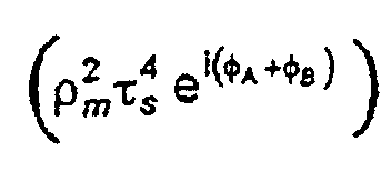 and third
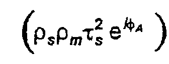 components interfere on detection throughout a full range of practical bend curvatures.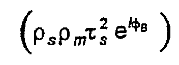
- The fibre optic linked
spectrometer 27a incorporates an array of pixel detector elements. The coherence length (Icl ) of radiation incident on the ith pixel is given bywhere OPL is the optical path length and subscripts SA and SB refer to propagation through the
sensor length 34 ininput 62c andoutput 66c cores respectively. In the embodiment herein described, this condition is satisfied by the commercially available Ocean Optics PC1000 fibre-linked spectrometer. - Only one interference pattern is generated in an embodiment of the invention which satisfies the condition of Equation (3) above. The intensity pattern across such an interferogram is represented by:

- This can be written in terms of the transmittance (T = τ2) and reflectance (R = ρ2) of the
splice 36 and mirrored end 38:
- The R and T values of the
splice 36 and mirroredend 38 in the embodiment described are Rs = 1/3, Ts = 2/3 and Rm = 1. These values maximise the depth of the [1 + cos (A - B)] modulation. In this embodiment therefore, the interferogram intensity variation is given by - Substituting Equation (1) for the values of A and B, the effect of fibre bending on Φ can be written:

- Second order terms in ε are at least four orders of magnitude less than first order terms and, to a very good approximation, can be neglected. The resultant phase difference arising from a bend curvature κ is thus:and the generated interferogram has intensity variation

- The slightly different doping levels in the
input 62c andoutput 66c cores enables the direction of bend curvature within this plane, i.e. whetherinput core 62c is compressed or extended, to be determined. Different doping levels ensure that η A (λ) ≠ η B (λ), Φ(Ls ,κ,λ) ≠ - Φ(Ls ,-κ,λ) and so Iout (Ls ,κ,λ) ≠ Iout (Ls ,-κ,λ). If ηA > η B , a positive curvature (κ) will result in an expanded fringe system in comparison with a negative curvature. Thesystem 10 is calibrated initially over a range of both positive and negative bend curvatures and it may become apparent at this stage that the frequency ranges of cosine fringes in the two regimes do not overlap. - The
superiuminescent diodes system 10 and broadband interferograms are generated. These interferograms are detected using the fibre optic linkedspectrometers core pair BMM fibre assembly 26 is dispersed and focused by thespectrometer 27a onto a linear detector array as a channelled spectrum. In this way one point (constant optical path difference) of the interferogram is sampled over a range of wavelengths. Another sampling technique which provides alternative embodiments of the invention derives from scanning the sensor length Ls . However scanning sensor length presents additional considerations which may not be acceptable in some applications. Practically it is not possible to change the length of thesensor length 34, as used in the specific embodiment employing wavelength scanning. An additional optical path element of variable length, such as that provided by a Michelson interferometer, must be included in the system as an external compensation for the optical path difference introduced by the bend. Interferograms may be produced either spatially or temporally. Spatial multiplexing of an interferogram allows for the possibility of fringe tracking. This involves continuous monitoring of a portion of the interferogram the motion of which is attributable to changes in the bend curvature of a sensing element. This constitutes a convenient monitoring technique which presents readily interpretable results, without the need for complex signal processing. - In the specific embodiment presented herein, the interferogram is sampled as a function of λ by the
spectrometer 27a. The sampling is discrete (at the position of each pixel of the detector) and results in a series of interferogram intensities measured at each pixel position. The detector has substantially identical pixels whose positions in the array increment linearly with wavelength. The measured channelled spectrum function is termed I(pi ) where pi represents the position of the ith pixel. A Fourier transform of this function is calculated to give the function I(qi ), where qi represents inverse pixel position (spatial frequency). Noise within the system appears at the high frequency end of this I(qi ) spectrum. DC background bias and source spectral profile give rise to a large peaks at the low frequency end. A bandpass filter is therefore applied to I(qi) to select an intermediate range which contains usable information I'(qi ). An analytical representation of the interferogram is then derived from I'(qi ) by taking the inverse Fourier transform to Re [I'(pi )], the real part of the representation, and then the Hilbert transform of this to Im [I'(pi )], the imaginary part. The analytical representation is thus: - For each component sampled along the detector array a value of (pi ) is calculated from the argument of the analytic signal I'(pi ). The phase is unwrapped to remove 2π discontinuities and a series of phase values across pixel positions are obtained. In this embodiment of the invention the wavelength variation across the broadband source output is approximately from 810nm to 840nm i.e. ~ 3.64%. The inverse wavelength range is therefore to a first order approximation, also broadly linear and no significant error will arise in taking pixel position to represent inverse wavelength. In fact this error is reduced still further by the bandpass filter which removes higher order components of the expansion. Thus unwrapped phase variation with inverse wavelength is effectively obtained by this signal processing technique. This phase variation can then be fitted to a polynomial. For the purpose of bend curvature a first order least-squares fit will generally be sufficient.
- The bend curvature (κ x ) may be extracted from the phase variation with inverse wavelength using Equation (4) above. The other parameters of Equation (4): η A (λ), η B (λ), r, K, and Ls can be used directly if their values are known but generally it will be more accurate to allow for system errors and irregularities and pre-calibrate the measurements for a range of known bend curvatures.
- By an analogous route the value of κy is extracted from interferometric measurement of radiation input to and output from the second
opposite core pair - Further information than solely bend curvature may be extracted from the phase variation with inverse wavelength if a higher order polynomial fit is made. For example, the second order coefficient may be used to discriminate between temperature variation and strain as known in the prior art and described in patent application PCT/GB94/01388.
- It is not necessary to use a 4-core BMM fibre in the
assembly 26. The fibre may contain any arrangement of core pairs which enables bend components to be measured in each core-pair plane. Neither is it necessary to have a symmetrical arrangement of cores. An alternative embodiment of the invention provides for a 6-core photonic crystal fibre to replace theBMM fibre 26. Such fibres are manufactured by close packing of cylindrical units and therefore have 6-fold symmetry at the fibre entry/exit faces. Multiple cores are defined by fabricating waveguides at appropriately positioned cylindrical units. Waveguide core positions must be well separated to reduce crosstalk and well cladded. In a 6-core symmetric embodiment components of bend curvature are measured in three planes of opposite core pairs. Three bend components provide for more accurate measurement of vector strain. In a 3-core embodiment three core-pairs in three planes are again available but cores must provide for simultaneous operation as both input and output cores or application is limited to bends which vary slowly with time. - Photonic fibres allow for waveguide cores to be more closely spaced before cross-coupling effects occur in comparison with the BMM fibres described herein. This allows the overall diameter of the fibre to be reduced, lowering further the disruption caused by sensor intrusion.
- The embodiment described illustrates an application of the invention to strain measurement. However, as noted above, temperature has a similar effect to strain on light propagating within a fibre. These multicored fibres can thus be used, in an analogous fashion, to measure temperature gradient. Such a measurement assumes that the optical path difference between two cores of a pair arises entirely from the temperature difference in the environments of each core. Note that as the cores in both BMM fibres and photonic crystals are very closely spaced, these fibres are primarily applicable to measurement of large temperature gradients.
- Another adaptation provides capability for simultaneous measurement of bend and temperature. In this embodiment, the cores of the BMM fibre exhibit high, stress-induced birefringence (HiBi cores), This provides a means, as described in patent application GB9606785.5, for sensitive discrimination between the effects of strain and temperature on fibre optical properties. A change in temperature modifies induced stresses in a HiBi core and so affects its birefringence. However, high birefringence shields the core from transverse stresses and so is substantially unaffected by stress. Thus both bending and temperature modify the length of the cores whereas only temperature affects the birefringence. Determination of these unequally-affected parameters allows discrimination between the effects of temperature and strain. The optical configuration and interrogation schemes are unchanged from those illustrated in Figure 1. Radiation is coupled into the HiBi cores in such a way as to equally populate both polarisation eigenmodes. Each physical
optical path
Claims (24)
- A bend sensor (10) incorporating a multicore fibre assembly (26) having first and second component cores (62, 66) and being arranged to convey radiation to and from a sensor length (34) comprising a bend sensing region of the fibre assembly (26) and thereafter to analysing means (27a, 27b) arranged to analyse radiation output from the fibre assembly (26), characterised in that the fibre assembly (26) incorporates coupling means (28) for coupling radiation propagating from the sensor length (34) in the first core (62b) to the second core (66b) for return to the sensor length (34), and reflecting means (36, 38) arranged to define the sensor length (34) by at least partial reflection of radiation thereat in both cores (62c, 66c), wherein the reflecting means (36, 38) and coupling means (28) are arranged to define first and second optical paths (122, 124) each of which traverses the sensor length (34) in a respective one of the cores (62c or 66c) but not the other (66c or 62c), and the analysing means (27a, 27b) is arranged to disperse interferograms formed between radiation contributions which have traversed the optical paths (122, 124).
- A bend sensor (10) according to Claim 1 characterised in that the first and second cores constitute a core pair (62, 66), component cores (62 to 68) of the multicore fibre (32 to 36) comprise a plurality such core pairs, and the coupling means is arranged to couple and reflect a portion of radiation propagating in each first core (62b or 64b) to a respective second core (66b or 68b) of the relevant pair (62/66, 64/68).
- A bend sensor (10) according to Claim 2 characterised in that it includes signal processing means arranged to derive interferogram phase variation from dispersed interferograms and to calculate bend curvature (κ) of the sensor length (34) from the phase variation.
- A bend sensor (10) according to Claim 3 characterised in that it is arranged to generate respective interferograms from radiation propagating within each core pair (62/66, 64/68), each interferogram arising from differences between respective first and second optical path lengths; and to calculate the resultant bend curvature (κ) as that component of bend curvature (κx, κy) in a plane containing the sensor length (34) of the respective core pair (62c, 66c).
- A bend sensor (10) according to Claim 4 characterised in that the multicore fibre (30 to 34) comprises at least two core pairs (62/66, 64/68) contained in non-coincident planes, the sensor (10) being arranged to calculate absolute bend magnitude and orientation from corresponding in-plane components of bend curvature.
- A bend sensor (10) according to Claim 5 characterised in that the two non-coplanar core pairs (62/66, 64/68) are contained in orthogonal planes.
- A bend sensor (10) according to Claim 5 or 6 characterised in that cores of each core pair (62/66, 64/68) have unequal effective refractive indices as appropriate to provide for curvature of one sign to result in an expanded fringe system compared to curvature of the opposite sign.
- A bend sensor (10) according to Claim 1 characterised in that the multicore fibre (30 to 34) is a bunched multiple monomode (BMM) fibre.
- A bend sensor (10) according to Claim 1 characterised in that the component cores are stress-induced highly birefringent (HiBi) cores.
- A bend sensor (10) according to Claim 1 characterised in that the multicored fibre (30, 32, 34) is a photonic crystal fibre.
- A bend sensor (10) according to Claim 1 characterised in that the fibre assembly (26) is arranged to receive incident broadband radiation and the analysing means (27a, 27b) is arranged to form a channelled spectrum by dispersing interferograms formed between radiation propagating in the first and second optical paths (122, 124) as a function of wavelength.
- A bend sensor (10) according to Claim 11 characterised in that it includes a superluminescent diode (12, 14) to provide the broadband radiation.
- A bend sensor (10) according to Claim 11 characterised in that broadband radiation propagating within the fibre (30, 32, 34) is provided by an Erbium Doped Fibre Amplifier.
- A bend sensor (10) according to Claim 11 characterised in that broadband radiation propagating within the fibre (30, 32, 34) is provided by a Praseodymium light source.
- A bend sensor (10) according to Claim 1 characterised in that it includes a scanning interferometer arranged to scan optical path lengths and whereby interferometer optical path differences compensate for the optical path difference between first and second optical paths (122, 124) and the analysing means (27a, 27b) is arranged to disperse interferograms formed between radiation propagating in the first and second optical paths (122, 124) as a function of the interferometer scan.
- A bend sensor (10) according to Claim 15 characterised in that the interferometer is arranged to perform a spatial scan.
- A bend sensor (10) according to Claim 15 characterised in that the interferometer is arranged to perform a temporal scan.
- A bend sensor (10) according to Claim 1 characterised in that the component cores (62, 64, 66, 68) are distributed in a symmetrical arrangement within the multicore fibre (30, 32, 34).
- A bend sensor (10) according to Claim 1 characterised in that the optical fibre (30, 32, 34) is less than 130µm in diameter.
- A bend sensor (10) according to Claim 1 characterised in that the coupling means (28) is a tandem coupler.
- A bend sensor (10) according to Claim 20 characterised in that the first and second cores constitute a core pair (62, 66), component cores (62 to 68) of the multicore fibre (32 to 36) comprise a plurality such core pairs, and the tandem coupler (28) incorporates a beamsplitter (88) comprising a base (114) and non-coplanar therewith respective pairs of planar reflecting faces for each core pair (62, 66) each extending from the base (114) towards an apex (116) and faces of each pair are disposed at least approximately at right angles to one another.
- A bend sensor (10) according to Claim 21 characterised in that the multicored fibre (30, 32, 34) has four symmetrically oriented component cores (62, 64, 66, 68) and the beamsplitter (88) comprises a square base (114), four triangular faces and an apex (116) wherein each triangular face extends from one side of the base (114) to the apex (116) and the perpendicular distance from the apex (116) to the base (114) is one half of the length of one side of the base (114).
- A bend sensor (10) according to Claim 21 or 22 characterised in that within the tandem coupler (28) the beamsplitter (88) is located intermediate to first and second planar microlens arrays (84, 86) wherein each microlens array (86) includes a respective microlens (92, 110, 96, 112) located a focal distance away from each component core (62, 64, 66, 68) and wherein the microlenses of each array are arranged in a common plane and the common planes of each lens array are mutually parallel and parallel to the base (114) of the beamsplitter (88).
- A temperature sensor (10) incorporating a multicore fibre assembly (26) having first and second component cores (62, 66) and being arranged to convey radiation to and from a sensor length (34) comprising a bend sensing region of the fibre assembly (26) and thereafter to analysing means (27a, 27b) arranged to analyse radiation output from the fibre assembly (26), characterised in that the fibre assembly (26) incorporates coupling means (28) for coupling radiation propagating from the sensor length (34) in the first core (62b) to the second core (66b) for return to the sensor length (34), and reflecting means (36, 38) arranged to define the sensor length (34) by at least partial reflection of radiation thereat in both cores (62c, 66c), wherein the reflecting means (36, 38) and coupling means (28) are arranged to define first and second optical paths (122, 124) each of which traverses the sensor length (34) in a respective one of the cores (62c or 66c) but not the other (66c or 62c), and the analysing means (27a, 27b) is arranged to disperse interferograms formed between radiation contributions which have traversed the optical paths (122, 124).
Priority Applications (1)
| Application Number | Priority Date | Filing Date | Title |
|---|---|---|---|
| EP01201885A EP1134556A3 (en) | 1997-06-20 | 1998-06-17 | Optical fibre bend sensor |
Applications Claiming Priority (3)
| Application Number | Priority Date | Filing Date | Title |
|---|---|---|---|
| GBGB9713018.1A GB9713018D0 (en) | 1997-06-20 | 1997-06-20 | Optical fibre bend sensor |
| GB9713018 | 1997-06-20 | ||
| PCT/GB1998/001780 WO1998059219A2 (en) | 1997-06-20 | 1998-06-17 | Optical fibre bend sensor |
Related Child Applications (1)
| Application Number | Title | Priority Date | Filing Date |
|---|---|---|---|
| EP01201885A Division EP1134556A3 (en) | 1997-06-20 | 1998-06-17 | Optical fibre bend sensor |
Publications (2)
| Publication Number | Publication Date |
|---|---|
| EP0990124A1 EP0990124A1 (en) | 2000-04-05 |
| EP0990124B1 true EP0990124B1 (en) | 2002-09-11 |
Family
ID=10814625
Family Applications (2)
| Application Number | Title | Priority Date | Filing Date |
|---|---|---|---|
| EP98930883A Expired - Lifetime EP0990124B1 (en) | 1997-06-20 | 1998-06-17 | Optical fibre bend sensor |
| EP01201885A Withdrawn EP1134556A3 (en) | 1997-06-20 | 1998-06-17 | Optical fibre bend sensor |
Family Applications After (1)
| Application Number | Title | Priority Date | Filing Date |
|---|---|---|---|
| EP01201885A Withdrawn EP1134556A3 (en) | 1997-06-20 | 1998-06-17 | Optical fibre bend sensor |
Country Status (8)
| Country | Link |
|---|---|
| US (2) | US6389187B1 (en) |
| EP (2) | EP0990124B1 (en) |
| JP (1) | JP2001525070A (en) |
| KR (1) | KR20010013998A (en) |
| CA (1) | CA2294150A1 (en) |
| DE (1) | DE69807875T2 (en) |
| GB (2) | GB9713018D0 (en) |
| WO (1) | WO1998059219A2 (en) |
Families Citing this family (296)
| Publication number | Priority date | Publication date | Assignee | Title |
|---|---|---|---|---|
| EP1026475A1 (en) * | 1999-02-05 | 2000-08-09 | Fujikura Ltd. | Optical fiber curvature measuring apparatus and correction method thereof |
| JP4619507B2 (en) * | 2000-09-26 | 2011-01-26 | 浜松ホトニクス株式会社 | Optical fiber coupling device, wavelength tunable device, pressure sensor, acceleration sensor, and optical device |
| JP2002098916A (en) * | 2000-09-26 | 2002-04-05 | Hamamatsu Photonics Kk | Optical device |
| JP4627362B2 (en) * | 2000-09-26 | 2011-02-09 | 浜松ホトニクス株式会社 | Tunable light source |
| JP2003043295A (en) * | 2001-07-31 | 2003-02-13 | Nippon Sheet Glass Co Ltd | Optical module unit and optical module using the same |
| US20040061863A1 (en) * | 2002-08-20 | 2004-04-01 | Digonnet Michel J.F. | Fiber optic sensors with reduced noise |
| US7738109B2 (en) * | 2002-08-20 | 2010-06-15 | The Board Of Trustees Of The Leland Stanford Junior University | Fiber optic sensor using a Bragg fiber |
| US20040187864A1 (en) * | 2003-03-24 | 2004-09-30 | Cindet, Llc | Inhalation device and method |
| US7027699B2 (en) * | 2003-05-21 | 2006-04-11 | The Hong Kong Polytechnic University | Optical fiber and optical fiber sensors |
| US7955357B2 (en) | 2004-07-02 | 2011-06-07 | Ellipse Technologies, Inc. | Expandable rod system to treat scoliosis and method of using the same |
| US7772541B2 (en) * | 2004-07-16 | 2010-08-10 | Luna Innnovations Incorporated | Fiber optic position and/or shape sensing based on rayleigh scatter |
| US20060013523A1 (en) * | 2004-07-16 | 2006-01-19 | Luna Innovations Incorporated | Fiber optic position and shape sensing device and method relating thereto |
| US7781724B2 (en) * | 2004-07-16 | 2010-08-24 | Luna Innovations Incorporated | Fiber optic position and shape sensing device and method relating thereto |
| FR2873505B1 (en) * | 2004-08-03 | 2007-05-25 | Orep Sarl Sarl | PERIMETER DETECTION SYSTEM BY INTERFEROMETRIC ANALYSIS |
| JP2007139698A (en) * | 2005-11-22 | 2007-06-07 | Mitsubishi Heavy Ind Ltd | Strain sensing-use optical fiber |
| US7790770B2 (en) | 2005-11-23 | 2010-09-07 | Bristol-Myers Squibb Company | Heterocyclic CETP inhibitors |
| US9962066B2 (en) | 2005-12-30 | 2018-05-08 | Intuitive Surgical Operations, Inc. | Methods and apparatus to shape flexible entry guides for minimally invasive surgery |
| US7930065B2 (en) | 2005-12-30 | 2011-04-19 | Intuitive Surgical Operations, Inc. | Robotic surgery system including position sensors using fiber bragg gratings |
| RU2008131050A (en) * | 2006-02-01 | 2010-03-10 | Афл Телекомьюникэйшнс Ллс (Us) | SENSOR AND METHOD OF VOLTAGE MEASUREMENT |
| US20070201793A1 (en) * | 2006-02-17 | 2007-08-30 | Charles Askins | Multi-core optical fiber and method of making and using same |
| US8989528B2 (en) | 2006-02-22 | 2015-03-24 | Hansen Medical, Inc. | Optical fiber grating sensors and methods of manufacture |
| US20070265503A1 (en) * | 2006-03-22 | 2007-11-15 | Hansen Medical, Inc. | Fiber optic instrument sensing system |
| US7768700B1 (en) | 2006-11-30 | 2010-08-03 | Lockheed Martin Corporation | Method and apparatus for optical gain fiber having segments of differing core sizes |
| US20080019704A1 (en) * | 2006-05-31 | 2008-01-24 | Campillo Anthony L | Interferometer-based chromatic dispersion monitor |
| US7664347B2 (en) * | 2006-06-07 | 2010-02-16 | Baker Hughes Incorporated | Multi-core optical fiber sensor |
| US7379631B2 (en) * | 2006-06-12 | 2008-05-27 | Baker Hughes Incorporated | Multi-core distributed temperature sensing fiber |
| CN104688327B (en) | 2006-06-13 | 2017-06-09 | 直观外科手术操作公司 | Minimally Invasive Surgical System |
| US7619743B2 (en) * | 2006-06-29 | 2009-11-17 | The Board Of Trustees Of The Leland Stanford Junior University | Optical sensor utilizing hollow-core photonic bandgap fiber with low phase thermal constant |
| US7512292B2 (en) | 2006-09-12 | 2009-03-31 | Weatherford/Lamb, Inc. | Multi-core strain compensated optical fiber temperature sensor |
| DE102006046778A1 (en) * | 2006-09-29 | 2008-04-03 | Siemens Ag | Fiber-optic sensor device, has mechanism in form of mode filter component and mode mixer arranged in or on optical fiber for producing balancing operation in fiber, and arranged close to coupling area between light source and fiber |
| DE102006048316A1 (en) * | 2006-10-12 | 2008-04-17 | Robert Bosch Gmbh | Optical fiber probe for interferometric measuring instrument, has reflection zone arranged in fiber for partial reflection of light rays guided in fiber, where reflection zone is arranged in fiber end piece |
| US7862502B2 (en) | 2006-10-20 | 2011-01-04 | Ellipse Technologies, Inc. | Method and apparatus for adjusting a gastrointestinal restriction device |
| US7941213B2 (en) * | 2006-12-28 | 2011-05-10 | Medtronic, Inc. | System and method to evaluate electrode position and spacing |
| EP3542701B1 (en) * | 2007-01-29 | 2021-03-10 | Intuitive Surgical Operations Inc. | System for controlling an instrument using shape sensors |
| US20090036900A1 (en) * | 2007-02-02 | 2009-02-05 | Hansen Medical, Inc. | Surgery methods using a robotic instrument system |
| US7324714B1 (en) | 2007-04-11 | 2008-01-29 | The United States Of America As Represented By The Secretary Of The Navy | Multicore fiber curvature sensor |
| CN101711125B (en) | 2007-04-18 | 2016-03-16 | 美敦力公司 | Long-term implantable active fixed medical electronic leads for non-fluoroscopy implants |
| US8050523B2 (en) * | 2007-04-20 | 2011-11-01 | Koninklijke Philips Electronics N.V. | Optical fiber shape sensing systems |
| US7876495B1 (en) * | 2007-07-31 | 2011-01-25 | Lockheed Martin Corporation | Apparatus and method for compensating for and using mode-profile distortions caused by bending optical fibers |
| US7924500B1 (en) | 2007-07-21 | 2011-04-12 | Lockheed Martin Corporation | Micro-structured fiber profiles for mitigation of bend-loss and/or mode distortion in LMA fiber amplifiers, including dual-core embodiments |
| WO2009023801A1 (en) | 2007-08-14 | 2009-02-19 | Hansen Medical, Inc. | Robotic instrument systems and methods utilizing optical fiber sensor |
| US8065085B2 (en) * | 2007-10-02 | 2011-11-22 | Gyrodata, Incorporated | System and method for measuring depth and velocity of instrumentation within a wellbore using a bendable tool |
| US20090112263A1 (en) | 2007-10-30 | 2009-04-30 | Scott Pool | Skeletal manipulation system |
| US11202707B2 (en) | 2008-03-25 | 2021-12-21 | Nuvasive Specialized Orthopedics, Inc. | Adjustable implant system |
| US8839798B2 (en) * | 2008-04-18 | 2014-09-23 | Medtronic, Inc. | System and method for determining sheath location |
| US8260395B2 (en) | 2008-04-18 | 2012-09-04 | Medtronic, Inc. | Method and apparatus for mapping a structure |
| US8494608B2 (en) * | 2008-04-18 | 2013-07-23 | Medtronic, Inc. | Method and apparatus for mapping a structure |
| US8532734B2 (en) | 2008-04-18 | 2013-09-10 | Regents Of The University Of Minnesota | Method and apparatus for mapping a structure |
| US8663120B2 (en) * | 2008-04-18 | 2014-03-04 | Regents Of The University Of Minnesota | Method and apparatus for mapping a structure |
| US8340751B2 (en) * | 2008-04-18 | 2012-12-25 | Medtronic, Inc. | Method and apparatus for determining tracking a virtual point defined relative to a tracked member |
| US7815376B2 (en) * | 2008-06-30 | 2010-10-19 | Intuitive Surgical Operations, Inc. | Fixture for shape-sensing optical fiber in a kinematic chain |
| US7720322B2 (en) * | 2008-06-30 | 2010-05-18 | Intuitive Surgical, Inc. | Fiber optic shape sensor |
| US20100030063A1 (en) * | 2008-07-31 | 2010-02-04 | Medtronic, Inc. | System and method for tracking an instrument |
| US11241257B2 (en) | 2008-10-13 | 2022-02-08 | Nuvasive Specialized Orthopedics, Inc. | Spinal distraction system |
| US8095317B2 (en) | 2008-10-22 | 2012-01-10 | Gyrodata, Incorporated | Downhole surveying utilizing multiple measurements |
| US8185312B2 (en) | 2008-10-22 | 2012-05-22 | Gyrodata, Incorporated | Downhole surveying utilizing multiple measurements |
| US8382756B2 (en) | 2008-11-10 | 2013-02-26 | Ellipse Technologies, Inc. | External adjustment device for distraction device |
| US8175681B2 (en) | 2008-12-16 | 2012-05-08 | Medtronic Navigation Inc. | Combination of electromagnetic and electropotential localization |
| US8065087B2 (en) | 2009-01-30 | 2011-11-22 | Gyrodata, Incorporated | Reducing error contributions to gyroscopic measurements from a wellbore survey system |
| US8197490B2 (en) | 2009-02-23 | 2012-06-12 | Ellipse Technologies, Inc. | Non-invasive adjustable distraction system |
| US9622792B2 (en) | 2009-04-29 | 2017-04-18 | Nuvasive Specialized Orthopedics, Inc. | Interspinous process device and method |
| US8087477B2 (en) * | 2009-05-05 | 2012-01-03 | Baker Hughes Incorporated | Methods and apparatuses for measuring drill bit conditions |
| US8780339B2 (en) | 2009-07-15 | 2014-07-15 | Koninklijke Philips N.V. | Fiber shape sensing systems and methods |
| US8494613B2 (en) | 2009-08-31 | 2013-07-23 | Medtronic, Inc. | Combination localization system |
| US8494614B2 (en) | 2009-08-31 | 2013-07-23 | Regents Of The University Of Minnesota | Combination localization system |
| EP2473116B1 (en) | 2009-09-04 | 2019-12-04 | NuVasive Specialized Orthopedics, Inc. | Bone growth device |
| US8773650B2 (en) | 2009-09-18 | 2014-07-08 | Intuitive Surgical Operations, Inc. | Optical position and/or shape sensing |
| US8355774B2 (en) * | 2009-10-30 | 2013-01-15 | Medtronic, Inc. | System and method to evaluate electrode position and spacing |
| US8183520B2 (en) | 2009-11-13 | 2012-05-22 | Intuitive Surgical Operations, Inc. | Optical fiber shape sensor calibration |
| US8488130B2 (en) | 2009-11-13 | 2013-07-16 | Intuitive Surgical Operations, Inc. | Method and system to sense relative partial-pose information using a shape sensor |
| US8957367B2 (en) | 2009-11-13 | 2015-02-17 | Intuitive Surgical Operations, Inc. | Shape sensor contained in a link of a kinematic chain with at least one pre-set perturbation and method to sense relative partial-pose information using the shape sensor |
| US8923678B2 (en) * | 2009-12-02 | 2014-12-30 | Ofs Fitel, Llc | Techniques for manipulating crosstalk in multicore fibers |
| US9285246B2 (en) | 2010-02-12 | 2016-03-15 | Intuitive Surgical Operations, Inc. | Method and system for absolute three-dimensional measurements using a twist-insensitive shape sensor |
| US20110282357A1 (en) | 2010-05-14 | 2011-11-17 | Intuitive Surgical Operations, Inc. | Surgical system architecture |
| WO2011153018A2 (en) | 2010-06-01 | 2011-12-08 | Luna Innovations Incorporated | Interferometric measurement with crosstalk suppression |
| US9248043B2 (en) | 2010-06-30 | 2016-02-02 | Ellipse Technologies, Inc. | External adjustment device for distraction device |
| EP2600768A2 (en) * | 2010-08-05 | 2013-06-12 | The UAB Research Foundation | Apparatuses and methods for evaluating a patient |
| WO2012021378A2 (en) | 2010-08-09 | 2012-02-16 | Ellipse Technologies, Inc. | Maintenance feature in magnetic implant |
| EP2616783B1 (en) * | 2010-09-17 | 2021-01-27 | Intuitive Surgical Operations Inc. | Interferometric measurement system and method for compensating for non-ideal multi-core optical fiber structure |
| US8827948B2 (en) | 2010-09-17 | 2014-09-09 | Hansen Medical, Inc. | Steerable catheters |
| US20120191083A1 (en) | 2011-01-20 | 2012-07-26 | Hansen Medical, Inc. | System and method for endoluminal and translumenal therapy |
| CN103327892B (en) * | 2011-01-27 | 2017-02-15 | 皇家飞利浦电子股份有限公司 | Shape sensing device-specific information storage and retrieval |
| WO2012112396A2 (en) | 2011-02-14 | 2012-08-23 | Ellipse Technologies, Inc. | Device and method for treating fractured bones |
| EP2721434B1 (en) * | 2011-06-14 | 2021-05-05 | Intuitive Surgical Operations, Inc. | Co-registration of cores in multicore optical fiber sensing systems |
| US20130030363A1 (en) | 2011-07-29 | 2013-01-31 | Hansen Medical, Inc. | Systems and methods utilizing shape sensing fibers |
| US10743794B2 (en) | 2011-10-04 | 2020-08-18 | Nuvasive Specialized Orthopedics, Inc. | Devices and methods for non-invasive implant length sensing |
| US20130303944A1 (en) | 2012-05-14 | 2013-11-14 | Intuitive Surgical Operations, Inc. | Off-axis electromagnetic sensor |
| US9452276B2 (en) | 2011-10-14 | 2016-09-27 | Intuitive Surgical Operations, Inc. | Catheter with removable vision probe |
| US10238837B2 (en) | 2011-10-14 | 2019-03-26 | Intuitive Surgical Operations, Inc. | Catheters with control modes for interchangeable probes |
| US9387048B2 (en) | 2011-10-14 | 2016-07-12 | Intuitive Surgical Operations, Inc. | Catheter sensor systems |
| US10016220B2 (en) | 2011-11-01 | 2018-07-10 | Nuvasive Specialized Orthopedics, Inc. | Adjustable magnetic devices and methods of using same |
| CN103134533B (en) * | 2011-12-02 | 2017-08-22 | 西安金和光学科技有限公司 | Based on twin-channel distribution type optical fiber sensing equipment and its operation method |
| EP2809249B1 (en) | 2012-02-03 | 2018-12-26 | Intuitive Surgical Operations, Inc. | Steerable flexible needle with embedded shape sensing |
| JPWO2013141112A1 (en) * | 2012-03-23 | 2015-08-03 | 住友電気工業株式会社 | Interference measurement device |
| US10039473B2 (en) | 2012-05-14 | 2018-08-07 | Intuitive Surgical Operations, Inc. | Systems and methods for navigation based on ordered sensor records |
| KR102171520B1 (en) | 2012-05-14 | 2020-10-29 | 인튜어티브 서지컬 오퍼레이션즈 인코포레이티드 | Systems and methods for deformation compensation using shape sensing |
| EP2849668B1 (en) | 2012-05-14 | 2018-11-14 | Intuitive Surgical Operations Inc. | Systems and methods for registration of a medical device using rapid pose search |
| EP3524184B1 (en) | 2012-05-14 | 2021-02-24 | Intuitive Surgical Operations Inc. | Systems for registration of a medical device using a reduced search space |
| US9588582B2 (en) | 2013-09-17 | 2017-03-07 | Medibotics Llc | Motion recognition clothing (TM) with two different sets of tubes spanning a body joint |
| US10321873B2 (en) | 2013-09-17 | 2019-06-18 | Medibotics Llc | Smart clothing for ambulatory human motion capture |
| US9582072B2 (en) | 2013-09-17 | 2017-02-28 | Medibotics Llc | Motion recognition clothing [TM] with flexible electromagnetic, light, or sonic energy pathways |
| US10602965B2 (en) | 2013-09-17 | 2020-03-31 | Medibotics | Wearable deformable conductive sensors for human motion capture including trans-joint pitch, yaw, and roll |
| US10716510B2 (en) | 2013-09-17 | 2020-07-21 | Medibotics | Smart clothing with converging/diverging bend or stretch sensors for measuring body motion or configuration |
| US20130338714A1 (en) | 2012-06-15 | 2013-12-19 | Arvin Chang | Magnetic implants with improved anatomical compatibility |
| US9429696B2 (en) | 2012-06-25 | 2016-08-30 | Intuitive Surgical Operations, Inc. | Systems and methods for reducing measurement error in optical fiber shape sensors |
| US9574911B2 (en) * | 2012-08-09 | 2017-02-21 | Corning Incorporated | Two-core optical fibers for distributed fiber sensors and systems |
| CN106562757B (en) | 2012-08-14 | 2019-05-14 | 直观外科手术操作公司 | The system and method for registration for multiple vision systems |
| CN107280671B (en) | 2012-08-14 | 2020-04-17 | 直观外科手术操作公司 | System and method for configuring components in minimally invasive instruments |
| KR101960839B1 (en) * | 2012-09-04 | 2019-03-22 | 삼성전자주식회사 | Force sensing apparatus and method of operating force sensing apparatus |
| US9044281B2 (en) | 2012-10-18 | 2015-06-02 | Ellipse Technologies, Inc. | Intramedullary implants for replacing lost bone |
| CN104902854B (en) | 2012-10-29 | 2017-10-03 | 诺威适骨科专科公司 | Adjustable device for knee arthritis |
| US20140188440A1 (en) | 2012-12-31 | 2014-07-03 | Intuitive Surgical Operations, Inc. | Systems And Methods For Interventional Procedure Planning |
| US9839481B2 (en) | 2013-03-07 | 2017-12-12 | Intuitive Surgical Operations, Inc. | Hybrid manual and robotic interventional instruments and methods of use |
| US9179938B2 (en) | 2013-03-08 | 2015-11-10 | Ellipse Technologies, Inc. | Distraction devices and method of assembling the same |
| JP6363165B2 (en) | 2013-03-15 | 2018-07-25 | インテュイティブ サージカル オペレーションズ, インコーポレイテッド | Shape sensor system for tracking interventional instruments and method of using the system |
| US10206747B2 (en) | 2013-05-15 | 2019-02-19 | Intuitive Surgical Operations, Inc. | Guide apparatus for delivery of a flexible instrument and methods of use |
| US9592095B2 (en) | 2013-05-16 | 2017-03-14 | Intuitive Surgical Operations, Inc. | Systems and methods for robotic medical system integration with external imaging |
| SE537516C2 (en) * | 2013-07-29 | 2015-05-26 | Niklas Salomonsson | Method and sensor for positioning a flexible element |
| CN114343608B (en) | 2013-07-29 | 2024-07-26 | 直观外科手术操作公司 | Shape sensor system with redundant sensing |
| US10226242B2 (en) | 2013-07-31 | 2019-03-12 | Nuvasive Specialized Orthopedics, Inc. | Noninvasively adjustable suture anchors |
| US9801734B1 (en) | 2013-08-09 | 2017-10-31 | Nuvasive, Inc. | Lordotic expandable interbody implant |
| CN105473098B (en) | 2013-08-15 | 2019-03-26 | 直观外科手术操作公司 | System and method for medical procedure validation |
| KR102356881B1 (en) | 2013-08-15 | 2022-02-03 | 인튜어티브 서지컬 오퍼레이션즈 인코포레이티드 | Graphical user interface for catheter positioning and insertion |
| US8941392B1 (en) * | 2013-08-17 | 2015-01-27 | Bend Labs, Inc. | Angular displacement sensor of compliant material |
| JP6567532B2 (en) | 2013-09-12 | 2019-08-28 | インテュイティブ サージカル オペレーションズ, インコーポレイテッド | Shape sensor system for locally movable targets |
| US10751094B2 (en) | 2013-10-10 | 2020-08-25 | Nuvasive Specialized Orthopedics, Inc. | Adjustable spinal implant |
| KR102313708B1 (en) | 2013-10-25 | 2021-10-19 | 인튜어티브 서지컬 오퍼레이션즈 인코포레이티드 | Flexible instrument with embedded actuation conduits |
| WO2015061674A1 (en) | 2013-10-25 | 2015-04-30 | Intuitive Surgical Operations, Inc. | Flexible instrument with grooved steerable tube |
| KR102337440B1 (en) | 2013-12-09 | 2021-12-10 | 인튜어티브 서지컬 오퍼레이션즈 인코포레이티드 | Systems and methods for device-aware flexible tool registration |
| CN114366181B (en) | 2013-12-13 | 2024-08-02 | 直观外科手术操作公司 | Telescopic biopsy needle |
| CN106170265B (en) | 2014-02-04 | 2020-06-30 | 直观外科手术操作公司 | System and method for non-rigid deformation of tissue for virtual navigation of interventional tools |
| US10912523B2 (en) | 2014-03-24 | 2021-02-09 | Intuitive Surgical Operations, Inc. | Systems and methods for anatomic motion compensation |
| CN111345867A (en) | 2014-04-28 | 2020-06-30 | 诺威适骨科专科公司 | remote control |
| GB201409230D0 (en) * | 2014-05-23 | 2014-07-09 | Qinetiq Ltd | Improvements to sensors |
| US9562844B2 (en) | 2014-06-30 | 2017-02-07 | Baker Hughes Incorporated | Systems and devices for sensing corrosion and deposition for oil and gas applications |
| EP3174490B1 (en) | 2014-07-28 | 2020-04-15 | Intuitive Surgical Operations, Inc. | Systems and methods for planning multiple interventional procedures |
| KR20220065894A (en) | 2014-07-28 | 2022-05-20 | 인튜어티브 서지컬 오퍼레이션즈 인코포레이티드 | Systems and methods for intraoperative segmentation |
| WO2016028858A1 (en) | 2014-08-22 | 2016-02-25 | Intuitive Surgical Operations, Inc. | Systems and methods for adaptive input mapping |
| US11033296B2 (en) | 2014-08-23 | 2021-06-15 | Intuitive Surgical Operations, Inc. | Systems and methods for dynamic trajectory control |
| KR102542848B1 (en) | 2014-08-23 | 2023-06-14 | 인튜어티브 서지컬 오퍼레이션즈 인코포레이티드 | Systems and methods for display of pathological data in an image guided procedure |
| WO2016032902A1 (en) | 2014-08-25 | 2016-03-03 | Intuitive Surgical Operations, Inc. | Systems and methods for medical instrument force sensing |
| US11273290B2 (en) | 2014-09-10 | 2022-03-15 | Intuitive Surgical Operations, Inc. | Flexible instrument with nested conduits |
| US10373719B2 (en) | 2014-09-10 | 2019-08-06 | Intuitive Surgical Operations, Inc. | Systems and methods for pre-operative modeling |
| US10314513B2 (en) | 2014-10-10 | 2019-06-11 | Intuitive Surgical Operations, Inc. | Systems and methods for reducing measurement error using optical fiber shape sensors |
| EP3206556B1 (en) | 2014-10-17 | 2026-03-25 | Intuitive Surgical Operations, Inc. | Systems and methods for reducing measurement error using optical fiber shape sensors |
| KR102588501B1 (en) | 2014-10-23 | 2023-10-11 | 누베이시브 스페셜라이즈드 오소페딕스, 인크. | Remotely adjustable interactive bone reshaping implant |
| CN107111684A (en) | 2014-11-13 | 2017-08-29 | 直观外科手术操作公司 | System and method for filtering localization data |
| US9927286B2 (en) | 2014-12-15 | 2018-03-27 | Schlumberger Technology Corporation | Seismic sensing with optical fiber |
| US10072497B2 (en) | 2014-12-15 | 2018-09-11 | Schlumberger Technology Corporation | Downhole acoustic wave sensing with optical fiber |
| EP4005515B1 (en) | 2014-12-26 | 2024-07-24 | NuVasive Specialized Orthopedics, Inc. | Systems for distraction |
| SE538575C2 (en) | 2015-01-22 | 2016-09-27 | Salomonsson Niklas | Sensor and method enabling the determination of the positionand orientation of a flexible element |
| US10238427B2 (en) | 2015-02-19 | 2019-03-26 | Nuvasive Specialized Orthopedics, Inc. | Systems and methods for vertebral adjustment |
| US9857245B2 (en) | 2015-03-09 | 2018-01-02 | Worcester Polytechnic Institute | Soft-body deformation and force sensing |
| EP3280312A4 (en) | 2015-04-06 | 2019-02-20 | Intuitive Surgical Operations Inc. | SYSTEMS AND METHODS FOR IMAGE-GUIDED SURGICAL RECORDING COMPENSATION |
| US9612102B2 (en) | 2015-04-17 | 2017-04-04 | Bend Labs, Inc | Compliant multi-region angular displacement and strain sensors |
| CN107660134B (en) | 2015-05-22 | 2021-06-29 | 直观外科手术操作公司 | System and method for image-guided surgical recording |
| WO2017030913A2 (en) | 2015-08-14 | 2017-02-23 | Intuitive Surgical Operations, Inc. | Systems and methods of registration for image-guided surgery |
| WO2017030915A1 (en) | 2015-08-14 | 2017-02-23 | Intuitive Surgical Operations, Inc. | Systems and methods of registration for image-guided surgery |
| CN108024693B (en) | 2015-09-10 | 2021-07-09 | 直观外科手术操作公司 | Systems and methods for utilizing tracking in image-guided medical procedures |
| WO2017066774A1 (en) | 2015-10-16 | 2017-04-20 | Nuvasive Specialized Orthopedics, Inc. | Adjustable devices for treating arthritis of the knee |
| JP6953409B2 (en) | 2015-12-10 | 2021-10-27 | ニューベイシブ スペシャライズド オーソペディックス,インコーポレイテッド | External adjustment device for extension device |
| DK3407812T3 (en) | 2016-01-28 | 2020-09-21 | Nuvasive Specialized Orthopedics Inc | Bone transport system |
| WO2017139548A1 (en) | 2016-02-10 | 2017-08-17 | Nuvasive Specialized Orthopedics, Inc. | Systems and methods for controlling multiple surgical variables |
| US10896506B2 (en) | 2016-02-12 | 2021-01-19 | Intuitive Surgical Operations, Inc | Systems and methods for using registered fluoroscopic images in image-guided surgery |
| US11399895B2 (en) | 2016-02-12 | 2022-08-02 | Intuitive Surgical Operations, Inc. | Systems and methods of pose estimation and calibration of perspective imaging system in image guided surgery |
| US10959644B2 (en) | 2016-03-24 | 2021-03-30 | Bend Labs Inc. | Compliant sensors for force sensing |
| KR20240035639A (en) | 2016-05-11 | 2024-03-15 | 인튜어티브 서지컬 오퍼레이션즈 인코포레이티드 | Redundant core in multicore optical fiber for safety |
| CN108135583B (en) | 2016-05-31 | 2022-07-15 | 直观外科手术操作公司 | Compliant Biopsy Needle System |
| EP4238490B1 (en) | 2016-06-30 | 2025-09-17 | Intuitive Surgical Operations, Inc. | Graphical user interface for displaying guidance information during an image-guided procedure |
| KR20190015581A (en) | 2016-06-30 | 2019-02-13 | 인튜어티브 서지컬 오퍼레이션즈 인코포레이티드 | System and method for fault reaction mechanism of medical robotic system |
| CN114886484A (en) | 2016-06-30 | 2022-08-12 | 直观外科手术操作公司 | Systems and methods for steerable elongated devices |
| EP4374768B1 (en) | 2016-06-30 | 2026-03-25 | Intuitive Surgical Operations, Inc. | Graphical user interface for displaying guidance information in a plurality of modes during an image-guided procedure |
| CN109310287B (en) | 2016-07-01 | 2023-01-03 | 直观外科手术操作公司 | Computer-aided medical system and control method thereof |
| CN109475721B (en) | 2016-07-08 | 2021-06-08 | 直观外科手术操作公司 | Guide device and method of use for conveying elongated equipment |
| CN109561934B (en) | 2016-08-23 | 2022-03-08 | 直观外科手术操作公司 | System and method for monitoring patient movement during medical procedure |
| US10729886B2 (en) | 2016-08-24 | 2020-08-04 | Intuitive Surgical Operations, Inc. | Axial support structure for a flexible elongate device |
| US10881385B2 (en) | 2016-09-13 | 2021-01-05 | Intuitive Surgical Operations, Inc. | Radial telescoping guide apparatus for delivery of a flexible instrument and methods of use |
| EP4623797A3 (en) | 2016-09-21 | 2025-12-03 | Intuitive Surgical Operations, Inc. | System for instrument buckling detection |
| US10682192B2 (en) | 2016-09-30 | 2020-06-16 | Intuitive Surgical Operations, Inc. | Variable-length guide apparatus for delivery of a flexible instrument and methods of use |
| WO2018064566A1 (en) | 2016-09-30 | 2018-04-05 | Intuitive Surgical Operations, Inc. | Systems and methods for entry point localization |
| EP3534818B1 (en) | 2016-11-02 | 2023-09-20 | Intuitive Surgical Operations, Inc. | Systems for continuous registration for image-guided surgery |
| WO2018106950A1 (en) | 2016-12-08 | 2018-06-14 | Intuitive Surgical Operations, Inc. | Systems and methods for navigation in image-guided medical procedures |
| JP7097883B2 (en) | 2016-12-09 | 2022-07-08 | インテュイティブ サージカル オペレーションズ, インコーポレイテッド | Systems and methods for sensing heat flux distribution in body tissues |
| WO2018122946A1 (en) * | 2016-12-27 | 2018-07-05 | オリンパス株式会社 | Shape acquisition method and control method for medical manipulator |
| CN110087576B (en) | 2017-01-09 | 2023-03-17 | 直观外科手术操作公司 | System and method for registering an elongated device to a three-dimensional image in an image-guided procedure |
| WO2018144698A1 (en) | 2017-02-01 | 2018-08-09 | Intuitive Surgical Operations, Inc. | Systems and methods of registration for image-guided procedures |
| CN110234262B (en) | 2017-02-06 | 2022-10-18 | 直观外科手术操作公司 | System and method for coupling components of a medical system |
| EP3595517B1 (en) | 2017-03-13 | 2024-11-20 | Intuitive Surgical Operations, Inc. | Systems and methods for medical procedures using optical coherence tomography sensing |
| EP3600112A4 (en) | 2017-03-22 | 2020-10-28 | Intuitive Surgical Operations Inc. | SYSTEMS AND PROCEDURES FOR INTELLIGENT SEEDING A REGISTRATION |
| RU176124U1 (en) * | 2017-04-12 | 2018-01-09 | Федеральное государственное унитарное предприятие "Всероссийский научно-исследовательский институт автоматики им. Н.Л. Духова" (ФГУП "ВНИИА") | Laser Focusing Unit |
| EP4539056A3 (en) | 2017-04-18 | 2025-06-25 | Intuitive Surgical Operations, Inc. | Graphical user interface for planning a procedure |
| US11937880B2 (en) | 2017-04-18 | 2024-03-26 | Intuitive Surgical Operations, Inc. | Graphical user interface for monitoring an image-guided procedure |
| WO2018237187A2 (en) | 2017-06-23 | 2018-12-27 | Intuitive Surgical Operations, Inc. | SYSTEMS AND METHODS FOR NAVIGATING A TARGET LOCATION DURING A MEDICAL ACT |
| EP4596017A3 (en) | 2017-07-21 | 2025-10-22 | Intuitive Surgical Operations, Inc. | Flexible elongate device systems and methods |
| JP7241061B2 (en) | 2017-07-31 | 2023-03-16 | インテュイティブ サージカル オペレーションズ, インコーポレイテッド | Systems and methods for safe operation of equipment |
| US10512515B2 (en) | 2017-07-31 | 2019-12-24 | Intuitive Surgical Operations, Inc. | Systems and methods for steerable elongate device |
| US12004830B2 (en) | 2017-08-16 | 2024-06-11 | Intuitive Surgical Operations , Inc. | Systems and methods for monitoring patient motion during a medical procedure |
| WO2019094099A1 (en) | 2017-11-10 | 2019-05-16 | Intuitive Surgical Operations, Inc. | Tension control in actuation of jointed instruments |
| WO2019099396A2 (en) | 2017-11-14 | 2019-05-23 | Intuitive Surgical Operations, Inc. | Systems and methods for cleaning endoscopic instruments |
| CN118161116A (en) | 2017-12-19 | 2024-06-11 | 直观外科手术操作公司 | Imaging system and method of use |
| EP4458306A3 (en) | 2018-03-29 | 2025-01-01 | Intuitive Surgical Operations, Inc. | Systems for flexible antennas |
| US12569300B2 (en) | 2018-04-25 | 2026-03-10 | Intuitive Surgical Operations, Inc. | Systems and methods related to elongate devices |
| CN112074867B (en) | 2018-05-11 | 2025-05-02 | 直观外科手术操作公司 | Systems and methods related to registration for image-guided surgery |
| US12048817B2 (en) | 2018-05-15 | 2024-07-30 | Intuitive Surgical Operations, Inc. | Backend mechanism of a catheter control system |
| WO2019241242A1 (en) | 2018-06-13 | 2019-12-19 | Intuitive Surgical Operations, Inc. | Systems and methods for powering an antenna |
| WO2019246240A1 (en) | 2018-06-19 | 2019-12-26 | Intuitive Surgical Operations, Inc. | Systems and methods for holding a flexible elongate device in a pose |
| WO2019245818A1 (en) | 2018-06-19 | 2019-12-26 | Intuitive Surgical Operations, Inc. | Systems and methods related to registration for image guided surgery |
| CN112601485B (en) | 2018-07-10 | 2024-10-29 | 直观外科手术操作公司 | System and method for orientation detection and tool installation |
| US12324560B2 (en) | 2018-07-10 | 2025-06-10 | Intuitive Surgical Operations, Inc. | Systems and methods for detecting an orientation of medical instruments |
| EP3821444A1 (en) | 2018-07-10 | 2021-05-19 | Intuitive Surgical Operations, Inc. | Systems and methods for tool detection and associated control modes |
| KR20210031924A (en) | 2018-07-10 | 2021-03-23 | 인튜어티브 서지컬 오퍼레이션즈 인코포레이티드 | Systems and methods for detecting the presence of medical tools |
| US11678788B2 (en) | 2018-07-25 | 2023-06-20 | Intuitive Surgical Operations, Inc. | Systems and methods for use of a variable stiffness flexible elongate device |
| US11080902B2 (en) | 2018-08-03 | 2021-08-03 | Intuitive Surgical Operations, Inc. | Systems and methods for generating anatomical tree structures |
| WO2020033318A1 (en) | 2018-08-07 | 2020-02-13 | Auris Health, Inc. | Combining strain-based shape sensing with catheter control |
| US11896316B2 (en) | 2018-08-23 | 2024-02-13 | Intuitive Surgical Operations, Inc. | Systems and methods for generating anatomic tree structures using backward pathway growth |
| US20210401508A1 (en) | 2018-10-04 | 2021-12-30 | Intuitive Surgical Operations, Inc. | Graphical user interface for defining an anatomical boundary |
| DE112019005020T5 (en) | 2018-10-04 | 2021-06-17 | Intuitive Surgical Operations, Inc. | Systems and methods for controlling steerable devices |
| EP3860497A1 (en) * | 2018-10-04 | 2021-08-11 | Intuitive Surgical Operations, Inc. | Systems and methods for device verification and sensor calibration |
| CN112804931B (en) | 2018-10-04 | 2024-11-22 | 直观外科手术操作公司 | System and method for motion control of a steerable device |
| US11737823B2 (en) | 2018-10-31 | 2023-08-29 | Intuitive Surgical Operations, Inc. | Antenna systems and methods of use |
| US11280863B2 (en) | 2018-11-02 | 2022-03-22 | Intuitive Surgical Operations, Inc. | Coiled antenna with fluid cooling |
| US11637378B2 (en) | 2018-11-02 | 2023-04-25 | Intuitive Surgical Operations, Inc. | Coiled dipole antenna |
| US11730537B2 (en) | 2018-11-13 | 2023-08-22 | Intuitive Surgical Operations, Inc. | Cooled chokes for ablation systems and methods of use |
| WO2020150165A1 (en) | 2019-01-14 | 2020-07-23 | Intuitive Surgical Operations, Inc. | System and method for automated docking |
| EP3922039A1 (en) | 2019-02-07 | 2021-12-15 | NuVasive Specialized Orthopedics, Inc. | Ultrasonic communication in medical devices |
| US11589901B2 (en) | 2019-02-08 | 2023-02-28 | Nuvasive Specialized Orthopedics, Inc. | External adjustment device |
| EP4663093A3 (en) | 2019-02-26 | 2026-01-21 | Intuitive Surgical Operations, Inc. | Systems for registration of patient anatomy |
| EP3705020A1 (en) * | 2019-03-05 | 2020-09-09 | FBGS Technologies GmbH | Methods and systems for shape sensing |
| CN113710145A (en) | 2019-03-15 | 2021-11-26 | 直观外科手术操作公司 | System for enhanced registration of patient anatomy |
| CN113766868A (en) | 2019-03-15 | 2021-12-07 | 直观外科手术操作公司 | System for determining bends and patient movement during medical procedures |
| WO2021045946A1 (en) | 2019-09-03 | 2021-03-11 | Nuvasive Specialized Orthopedics, Inc. | Acoustic reporting for dynamic implants |
| WO2021062253A1 (en) | 2019-09-26 | 2021-04-01 | Intuitive Surgical Operations, Inc. | Method and system for controlling flexible devices in presence of abnormal sensor signals |
| US12188760B2 (en) | 2019-10-31 | 2025-01-07 | Optonics Co., Ltd | Special optical fiber for measuring 3D curved shape, manufacturing method thereof, and system for measuring 3D curved shape by using special optical fiber |
| US12144564B2 (en) * | 2019-11-08 | 2024-11-19 | Intuitive Surgical Operations, Inc. | Systems and methods for registering an instrument to an image using change in instrument position data |
| CN114787868A (en) | 2019-11-08 | 2022-07-22 | 直观外科手术操作公司 | System and method for registering an instrument to an image using point cloud data |
| CN114867425B (en) | 2019-12-20 | 2026-02-03 | 直观外科手术操作公司 | System for progressive registration |
| US12383341B2 (en) | 2019-12-30 | 2025-08-12 | Intuitive Surgical Operations, Inc. | Systems and methods for automatically generating an anatomical boundary |
| CN115023194B (en) | 2019-12-30 | 2026-05-01 | 直观外科手术操作公司 | System and method for indicating proximity to anatomical boundaries |
| EP4106658A1 (en) | 2020-02-21 | 2022-12-28 | Intuitive Surgical Operations, Inc. | Systems and methods for delivering targeted therapy |
| WO2021183689A1 (en) | 2020-03-13 | 2021-09-16 | Intuitive Surgical Operations, Inc. | Alignment of a connector interface |
| CN115243637A (en) | 2020-03-24 | 2022-10-25 | 直观外科手术操作公司 | System and method for registering an instrument to an image using point cloud data and endoscopic image data |
| WO2021194850A1 (en) | 2020-03-27 | 2021-09-30 | Intuitive Surgical Operations, Inc. | Mitigation of registration data oversampling |
| WO2021207264A2 (en) | 2020-04-10 | 2021-10-14 | Intuitive Surgical Operations, Inc. | Flexible instruments with patterned antenna assemblies having variable recoverable flexibility |
| WO2022005621A1 (en) | 2020-06-30 | 2022-01-06 | Intuitive Surgical Operations, Inc. | Systems for evaluating registerability of anatomic models and associated methods |
| US12605192B2 (en) | 2020-07-15 | 2026-04-21 | Globus Medical, Inc. | Ultrasonic communication in adjustable implants |
| CN116368573A (en) | 2020-08-10 | 2023-06-30 | 直观外科手术操作公司 | Conversion and transmission of real-time volumetric image data for medical devices |
| WO2022035709A1 (en) | 2020-08-11 | 2022-02-17 | Intuitive Surgical Operations, Inc. | Systems for planning and performing biopsy procedures and associated methods |
| CN116322555A (en) | 2020-08-13 | 2023-06-23 | 直观外科手术操作公司 | Alerts and mitigates deviations in anatomical feature orientation from previous images to real-time interrogation |
| US12213708B2 (en) | 2020-09-08 | 2025-02-04 | Nuvasive Specialized Orthopedics, Inc. | Remote control module for adjustable implants |
| RU2765631C1 (en) * | 2020-09-28 | 2022-02-01 | Акционерное Общество "Институт "Оргэнергострой" | Fence with a linear part with an open interferometer with two arms |
| WO2022094874A1 (en) * | 2020-11-05 | 2022-05-12 | Leoni Kabel Gmbh | Sensing device |
| CN116472003A (en) | 2020-11-11 | 2023-07-21 | 直观外科手术操作公司 | Tension Control of Asymmetric Flexible Devices |
| WO2022115877A1 (en) | 2020-11-30 | 2022-06-02 | Intuitive Surgical Operations, Inc. | Systems for retracting and adjusting elongate flexible devices and associated methods |
| EP4271310B1 (en) | 2020-12-30 | 2026-04-29 | Intuitive Surgical Operations, Inc. | Systems for integrating intraoperative image data with minimally invasive medical techniques |
| WO2022146996A1 (en) | 2020-12-30 | 2022-07-07 | Intuitive Surgical Operations, Inc. | Systems for updating a graphical user interface based upon intraoperative imaging |
| CN116916847A (en) | 2021-01-04 | 2023-10-20 | 直观外科手术操作公司 | Systems for image-based registration and related methods |
| CN116940297A (en) | 2021-01-04 | 2023-10-24 | 直观外科手术操作公司 | Dynamic image-based positioning system |
| US11806054B2 (en) | 2021-02-23 | 2023-11-07 | Nuvasive Specialized Orthopedics, Inc. | Adjustable implant, system and methods |
| EP4304484B1 (en) | 2021-03-10 | 2025-02-26 | Intuitive Surgical Operations, Inc. | Systems and methods for registering intraoperative image data |
| DE112022002005T8 (en) | 2021-04-07 | 2024-02-22 | Intuitive Surgical Operations, Inc. | Systems, methods and medium containing instructions for connecting model structures representing anatomical pathways |
| CN117396915A (en) | 2021-04-08 | 2024-01-12 | 直观外科手术操作公司 | Systems and associated methods for image resampling |
| US20240238049A1 (en) | 2021-05-11 | 2024-07-18 | Intuitive Surgical Operations, Inc. | Medical instrument guidance systems and associated methods |
| US11737787B1 (en) | 2021-05-27 | 2023-08-29 | Nuvasive, Inc. | Bone elongating devices and methods of use |
| CN113375592B (en) * | 2021-06-04 | 2022-09-02 | 哈尔滨工程大学 | Bending measurement device based on optical fiber mode dispersion |
| AU2022325024A1 (en) | 2021-08-03 | 2024-02-22 | Nuvasive Specialized Orthopedics, Inc. | Adjustable implant |
| US12345924B2 (en) | 2021-08-18 | 2025-07-01 | Intuitive Surgical Operations, Inc. | Systems and methods for optical fiber alignment |
| EP4710861A3 (en) | 2021-09-03 | 2026-05-20 | Intuitive Surgical Operations | Elongated ultrasonic instrument systems and methods |
| CN118318255A (en) | 2021-09-28 | 2024-07-09 | 直观外科手术操作公司 | System and method for target nodule identification |
| EP4408327A1 (en) | 2021-09-28 | 2024-08-07 | Intuitive Surgical Operations, Inc. | Navigation assistance for an instrument |
| US12307581B2 (en) | 2021-09-28 | 2025-05-20 | Intuitive Surgical Operations, Inc. | Elongate device references for image-guided procedures |
| CN118302127A (en) | 2021-10-08 | 2024-07-05 | 直观外科手术操作公司 | Medical instrument guidance system including a guidance system for percutaneous nephrolithotomy procedures, and associated devices and methods |
| US20250049423A1 (en) | 2021-11-12 | 2025-02-13 | Intuitive Surgical Operations, Inc. | Biopsy tool |
| WO2023129934A1 (en) | 2021-12-31 | 2023-07-06 | Intuitive Surgical Operations, Inc. | Systems and methods for integrating intra-operative image data with minimally invasive medical techniques |
| US20250268677A1 (en) | 2022-04-20 | 2025-08-28 | Intuitive Surgical Operations, Inc. | Systems and methods for positioning medical instruments |
| WO2023220391A1 (en) | 2022-05-13 | 2023-11-16 | Intuitive Surgical Operations, Inc. | Systems and methods for lymph node assessment |
| WO2023225052A1 (en) | 2022-05-18 | 2023-11-23 | Intuitive Surgical Operations, Inc. | Medical procedures and systems using active implants |
| US12551240B2 (en) | 2022-06-13 | 2026-02-17 | Nuvasive Inc. | Distraction loss magnet on-off mechanism |
| EP4547137A1 (en) | 2022-06-29 | 2025-05-07 | Intuitive Surgical Operations, Inc. | Systems and methods for determining a deployment location of a medical instrument |
| US12458417B2 (en) | 2022-08-15 | 2025-11-04 | Nuvasive Specialized Orthopedics Inc. | Intermedullary lengthening implant with integrated load sensor |
| US20260097185A1 (en) | 2022-09-19 | 2026-04-09 | Intuitive Surgical Operations, Inc. | Systems and methods for varying bending stiffness of a flexible elongate device |
| WO2024064861A1 (en) | 2022-09-23 | 2024-03-28 | Intuitive Surgical Operations, Inc. | Imaging orientation planning for external imaging devices |
| US12508058B2 (en) | 2022-10-07 | 2025-12-30 | Nuvasive Specialized Orthopedics, Inc. | Adjustable tether implant |
| WO2024192012A1 (en) | 2023-03-13 | 2024-09-19 | Intuitive Surgical Operations, Inc. | Systems and methods for milestone detection with a spatial context |
| WO2024206553A1 (en) | 2023-03-31 | 2024-10-03 | Intuitive Surgical Operations, Inc. | Systems and methods for providing navigation guidance for an elongate device |
| EP4694796A1 (en) | 2023-04-11 | 2026-02-18 | Intuitive Surgical Operations, Inc. | Surgical stapling instruments and control systems for such instruments |
| US12558133B2 (en) | 2023-04-25 | 2026-02-24 | Nuvasive, Inc. | Flat plate mechanisms for bone lengthening |
| US12533164B2 (en) | 2023-05-03 | 2026-01-27 | Nuvasive Specialized Orthopedics, Inc. | Adjustable implant |
| EP4709312A1 (en) | 2023-05-08 | 2026-03-18 | Intuitive Surgical Operations, Inc. | Systems and methods for intraoperatively updating a graphical user interface based on intraoperative imaging data |
| WO2024249986A1 (en) | 2023-06-02 | 2024-12-05 | Intuitive Surgical Operations, Inc. | Surgical clip applier instruments with articulating jaws |
| WO2025064464A1 (en) | 2023-09-21 | 2025-03-27 | Intuitive Surgical Operations, Inc. | Medical tool with signal window and methods of use |
| WO2025155653A1 (en) | 2024-01-16 | 2025-07-24 | Intuitive Surgical Operations, Inc. | Collapsible circular staplers |
| WO2025155666A1 (en) | 2024-01-16 | 2025-07-24 | Intuitive Surgical Operations, Inc. | Circular stapling instrument |
| WO2025155694A1 (en) | 2024-01-16 | 2025-07-24 | Intuitive Surgical Operations, Inc. | Circular stapling systems and instruments |
| WO2025155683A1 (en) | 2024-01-16 | 2025-07-24 | Intuitive Surgical Operations, Inc. | Circular stapling instrument |
| WO2026019776A1 (en) | 2024-07-16 | 2026-01-22 | Intuitive Surgical Operations, Inc. | Atraumatic circular stapling instrument |
| WO2026030351A1 (en) | 2024-07-30 | 2026-02-05 | Intuitive Surgical Operations, Inc. | Systems and methods for reducing fogging of an optical surface of an imaging device |
Family Cites Families (10)
| Publication number | Priority date | Publication date | Assignee | Title |
|---|---|---|---|---|
| DE3019956A1 (en) * | 1980-05-24 | 1981-12-03 | Ibm Deutschland Gmbh, 7000 Stuttgart | MODULAR, FIBER OPTICAL COMMUNICATION SYSTEM |
| JPS59226832A (en) * | 1983-06-07 | 1984-12-20 | Yokogawa Hokushin Electric Corp | Optical ic sensor |
| US5221998A (en) * | 1989-10-24 | 1993-06-22 | Asahi Kogaku Kogyo Kabushiki Kaisha | Joined prism assembly and method and apparatus for manufacturing same |
| JPH04269701A (en) * | 1991-02-25 | 1992-09-25 | Ando Electric Co Ltd | Band pass filter module for light signal |
| US5355249A (en) * | 1992-04-21 | 1994-10-11 | Matsushita Electric Industrial Co., Ltd. | Optical passive components |
| US5420688A (en) * | 1992-12-14 | 1995-05-30 | Farah; John | Interferometric fiber optic displacement sensor |
| US5367583A (en) | 1994-02-09 | 1994-11-22 | University Of Maryland | Fiber optic stress-corrosion sensor and system |
| AUPM804394A0 (en) * | 1994-09-13 | 1994-10-06 | Future Fibre Technologies Pty Ltd | Method for producing fibre optic modalmetric sensors and applications thereof |
| US5566196A (en) * | 1994-10-27 | 1996-10-15 | Sdl, Inc. | Multiple core fiber laser and optical amplifier |
| US5563967A (en) * | 1995-06-07 | 1996-10-08 | Mcdonnell Douglas Corporation | Fiber optic sensor having a multicore optical fiber and an associated sensing method |
-
1997
- 1997-06-20 GB GBGB9713018.1A patent/GB9713018D0/en not_active Ceased
-
1998
- 1998-06-17 WO PCT/GB1998/001780 patent/WO1998059219A2/en not_active Ceased
- 1998-06-17 EP EP98930883A patent/EP0990124B1/en not_active Expired - Lifetime
- 1998-06-17 US US09/446,325 patent/US6389187B1/en not_active Expired - Lifetime
- 1998-06-17 JP JP50398199A patent/JP2001525070A/en active Pending
- 1998-06-17 CA CA002294150A patent/CA2294150A1/en not_active Abandoned
- 1998-06-17 EP EP01201885A patent/EP1134556A3/en not_active Withdrawn
- 1998-06-17 GB GB9929023A patent/GB2341445B/en not_active Expired - Fee Related
- 1998-06-17 DE DE69807875T patent/DE69807875T2/en not_active Expired - Fee Related
- 1998-06-17 KR KR19997012026A patent/KR20010013998A/en not_active Ceased
-
2002
- 2002-01-24 US US10/053,900 patent/US6621956B2/en not_active Expired - Lifetime
Also Published As
| Publication number | Publication date |
|---|---|
| US6621956B2 (en) | 2003-09-16 |
| GB9713018D0 (en) | 1997-08-27 |
| GB2341445A (en) | 2000-03-15 |
| EP1134556A2 (en) | 2001-09-19 |
| US20020097960A1 (en) | 2002-07-25 |
| GB2341445B (en) | 2002-01-02 |
| EP1134556A3 (en) | 2002-04-10 |
| WO1998059219A2 (en) | 1998-12-30 |
| KR20010013998A (en) | 2001-02-26 |
| DE69807875D1 (en) | 2002-10-17 |
| CA2294150A1 (en) | 1998-12-30 |
| EP0990124A1 (en) | 2000-04-05 |
| WO1998059219A3 (en) | 1999-04-29 |
| GB9929023D0 (en) | 2000-02-02 |
| US6389187B1 (en) | 2002-05-14 |
| JP2001525070A (en) | 2001-12-04 |
| DE69807875T2 (en) | 2003-05-22 |
Similar Documents
| Publication | Publication Date | Title |
|---|---|---|
| US6389187B1 (en) | Optical fiber bend sensor | |
| US20240183691A1 (en) | Methods and apparatus for determining shape parameter(s) using a sensing fiber having a single core with multiple light propagating modes | |
| US4928005A (en) | Multiple-point temperature sensor using optic fibers | |
| EP0890081B1 (en) | Sensor system | |
| EP2721434B1 (en) | Co-registration of cores in multicore optical fiber sensing systems | |
| Gander et al. | Two-axis bend measurement using multicore optical fibre | |
| WO2007003876A1 (en) | Fiber optic temperature and pressure sensor and system incorporating same | |
| JP7600257B2 (en) | A system for measuring microbends and arbitrary small deformations along three-dimensional space | |
| Yao et al. | 7-core fiber-based high-resolution omnidirectional vector bending sensor enabled by microwave photonics filter | |
| CN109374028B (en) | A Distributed Multiplexing Demodulation System Based on Cascaded Long Period Fiber Bragg Gratings | |
| Obaton et al. | Tilted fibre Bragg gratings and phase sensitive-optical low coherence interferometry for refractometry and liquid level sensing | |
| Kashen et al. | The influence of no-core fibre length on the sensitivity Optical fibre Humidity sensor | |
| CN113167566A (en) | High-Resolution Distributed Sensor Using Offset-Core Fibers | |
| Cumunel et al. | Long-gage optical fiber extensometers for dynamic evaluation of structures | |
| Gander et al. | Bend measurement using multicore optical fiber | |
| Li et al. | Vector bending sensor based on low-cost single-channel measurement and highly reliable three-peak reconstruction algorithm | |
| CN112859237B (en) | Composite detection device based on multi-core optical fiber sensor | |
| Burnett et al. | Optical Fibre‐based Vectoral Shape Sensor | |
| CN111220187B (en) | Cascaded long-period fiber grating multiplexing demodulation device based on low-coherence interference principle | |
| Yuan | Recent progress of multi-core fiber based integrated interferometers | |
| Yuan | Recent progress of in-fiber integrated interferometers | |
| Jahed et al. | Enhanced resolution fiber optic strain sensor based on mach-zehnder interferometer and displacement sensing principles | |
| Oriana | 3D reconstruction of the shape of optical fibers subjected to mechanical deformations | |
| Shih | Concentric-core optical fiber sensors | |
| Dokulilová et al. | Strain sensor with low-temperature sensitivity based on a weakly multimode optical fibre using coherence multiplexing |
Legal Events
| Date | Code | Title | Description |
|---|---|---|---|
| PUAI | Public reference made under article 153(3) epc to a published international application that has entered the european phase |
Free format text: ORIGINAL CODE: 0009012 |
|
| 17P | Request for examination filed |
Effective date: 19991210 |
|
| AK | Designated contracting states |
Kind code of ref document: A1 Designated state(s): DE FR GB IT NL |
|
| 17Q | First examination report despatched |
Effective date: 20010220 |
|
| RAP1 | Party data changed (applicant data changed or rights of an application transferred) |
Owner name: QINETIQ LIMITED |
|
| GRAG | Despatch of communication of intention to grant |
Free format text: ORIGINAL CODE: EPIDOS AGRA |
|
| GRAG | Despatch of communication of intention to grant |
Free format text: ORIGINAL CODE: EPIDOS AGRA |
|
| GRAH | Despatch of communication of intention to grant a patent |
Free format text: ORIGINAL CODE: EPIDOS IGRA |
|
| RBV | Designated contracting states (corrected) |
Designated state(s): DE FR GB IT NL |
|
| GRAH | Despatch of communication of intention to grant a patent |
Free format text: ORIGINAL CODE: EPIDOS IGRA |
|
| GRAA | (expected) grant |
Free format text: ORIGINAL CODE: 0009210 |
|
| AK | Designated contracting states |
Kind code of ref document: B1 Designated state(s): DE FR GB IT NL |
|
| REG | Reference to a national code |
Ref country code: GB Ref legal event code: FG4D |
|
| REF | Corresponds to: |
Ref document number: 69807875 Country of ref document: DE Date of ref document: 20021017 |
|
| ET | Fr: translation filed | ||
| PGFP | Annual fee paid to national office [announced via postgrant information from national office to epo] |
Ref country code: NL Payment date: 20030522 Year of fee payment: 6 |
|
| PG25 | Lapsed in a contracting state [announced via postgrant information from national office to epo] |
Ref country code: GB Free format text: LAPSE BECAUSE OF NON-PAYMENT OF DUE FEES Effective date: 20030617 |
|
| PLBE | No opposition filed within time limit |
Free format text: ORIGINAL CODE: 0009261 |
|
| STAA | Information on the status of an ep patent application or granted ep patent |
Free format text: STATUS: NO OPPOSITION FILED WITHIN TIME LIMIT |
|
| 26N | No opposition filed |
Effective date: 20030612 |
|
| GBPC | Gb: european patent ceased through non-payment of renewal fee |
Effective date: 20030617 |
|
| PG25 | Lapsed in a contracting state [announced via postgrant information from national office to epo] |
Ref country code: NL Free format text: LAPSE BECAUSE OF NON-PAYMENT OF DUE FEES Effective date: 20050101 |
|
| NLV4 | Nl: lapsed or anulled due to non-payment of the annual fee |
Effective date: 20050101 |
|
| PGFP | Annual fee paid to national office [announced via postgrant information from national office to epo] |
Ref country code: FR Payment date: 20090615 Year of fee payment: 12 |
|
| PGFP | Annual fee paid to national office [announced via postgrant information from national office to epo] |
Ref country code: DE Payment date: 20090622 Year of fee payment: 12 |
|
| PGFP | Annual fee paid to national office [announced via postgrant information from national office to epo] |
Ref country code: IT Payment date: 20090627 Year of fee payment: 12 |
|
| REG | Reference to a national code |
Ref country code: FR Ref legal event code: ST Effective date: 20110228 |
|
| PG25 | Lapsed in a contracting state [announced via postgrant information from national office to epo] |
Ref country code: IT Free format text: LAPSE BECAUSE OF NON-PAYMENT OF DUE FEES Effective date: 20100617 |
|
| PG25 | Lapsed in a contracting state [announced via postgrant information from national office to epo] |
Ref country code: DE Free format text: LAPSE BECAUSE OF NON-PAYMENT OF DUE FEES Effective date: 20110101 |
|
| PG25 | Lapsed in a contracting state [announced via postgrant information from national office to epo] |
Ref country code: FR Free format text: LAPSE BECAUSE OF NON-PAYMENT OF DUE FEES Effective date: 20100630 |