EP0990100B1 - Schnellkupplung mit schnappverriegelungshalter zur verbesserten befestigung - Google Patents
Schnellkupplung mit schnappverriegelungshalter zur verbesserten befestigung Download PDFInfo
- Publication number
- EP0990100B1 EP0990100B1 EP98919855A EP98919855A EP0990100B1 EP 0990100 B1 EP0990100 B1 EP 0990100B1 EP 98919855 A EP98919855 A EP 98919855A EP 98919855 A EP98919855 A EP 98919855A EP 0990100 B1 EP0990100 B1 EP 0990100B1
- Authority
- EP
- European Patent Office
- Prior art keywords
- housing
- retainer
- legs
- male
- quick connector
- Prior art date
- Legal status (The legal status is an assumption and is not a legal conclusion. Google has not performed a legal analysis and makes no representation as to the accuracy of the status listed.)
- Expired - Lifetime
Links
- 238000003780 insertion Methods 0.000 claims description 9
- 230000037431 insertion Effects 0.000 claims description 9
- 230000001154 acute effect Effects 0.000 claims description 4
- 238000004891 communication Methods 0.000 claims description 3
- 230000013011 mating Effects 0.000 claims description 2
- 230000008878 coupling Effects 0.000 description 17
- 238000010168 coupling process Methods 0.000 description 17
- 238000005859 coupling reaction Methods 0.000 description 17
- 230000000694 effects Effects 0.000 description 7
- 230000000007 visual effect Effects 0.000 description 5
- 239000012530 fluid Substances 0.000 description 2
- 238000000926 separation method Methods 0.000 description 2
- 230000004323 axial length Effects 0.000 description 1
- 239000011324 bead Substances 0.000 description 1
- 230000002093 peripheral effect Effects 0.000 description 1
- 229920001470 polyketone Polymers 0.000 description 1
- 125000006850 spacer group Chemical group 0.000 description 1
- 238000012795 verification Methods 0.000 description 1
Images


Classifications
-
- F—MECHANICAL ENGINEERING; LIGHTING; HEATING; WEAPONS; BLASTING
- F16—ENGINEERING ELEMENTS AND UNITS; GENERAL MEASURES FOR PRODUCING AND MAINTAINING EFFECTIVE FUNCTIONING OF MACHINES OR INSTALLATIONS; THERMAL INSULATION IN GENERAL
- F16L—PIPES; JOINTS OR FITTINGS FOR PIPES; SUPPORTS FOR PIPES, CABLES OR PROTECTIVE TUBING; MEANS FOR THERMAL INSULATION IN GENERAL
- F16L37/00—Couplings of the quick-acting type
- F16L37/08—Couplings of the quick-acting type in which the connection between abutting or axially overlapping ends is maintained by locking members
- F16L37/12—Couplings of the quick-acting type in which the connection between abutting or axially overlapping ends is maintained by locking members using hooks, pawls, or other movable or insertable locking members
- F16L37/14—Joints secured by inserting between mating surfaces an element, e.g. a piece of wire, a pin, a chain
- F16L37/142—Joints secured by inserting between mating surfaces an element, e.g. a piece of wire, a pin, a chain where the securing element is inserted tangentially
- F16L37/144—Joints secured by inserting between mating surfaces an element, e.g. a piece of wire, a pin, a chain where the securing element is inserted tangentially the securing element being U-shaped
-
- F—MECHANICAL ENGINEERING; LIGHTING; HEATING; WEAPONS; BLASTING
- F16—ENGINEERING ELEMENTS AND UNITS; GENERAL MEASURES FOR PRODUCING AND MAINTAINING EFFECTIVE FUNCTIONING OF MACHINES OR INSTALLATIONS; THERMAL INSULATION IN GENERAL
- F16L—PIPES; JOINTS OR FITTINGS FOR PIPES; SUPPORTS FOR PIPES, CABLES OR PROTECTIVE TUBING; MEANS FOR THERMAL INSULATION IN GENERAL
- F16L2201/00—Special arrangements for pipe couplings
- F16L2201/10—Indicators for correct coupling
-
- Y—GENERAL TAGGING OF NEW TECHNOLOGICAL DEVELOPMENTS; GENERAL TAGGING OF CROSS-SECTIONAL TECHNOLOGIES SPANNING OVER SEVERAL SECTIONS OF THE IPC; TECHNICAL SUBJECTS COVERED BY FORMER USPC CROSS-REFERENCE ART COLLECTIONS [XRACs] AND DIGESTS
- Y10—TECHNICAL SUBJECTS COVERED BY FORMER USPC
- Y10S—TECHNICAL SUBJECTS COVERED BY FORMER USPC CROSS-REFERENCE ART COLLECTIONS [XRACs] AND DIGESTS
- Y10S285/00—Pipe joints or couplings
- Y10S285/921—Snap-fit
Definitions
- Snap-fit or quick connectors are employed in a wide range of applications, particularly, for joining fluid carrying conduits in automotive and industrial application.
- a retainer is fixedly mounted within a bore in a housing of a female connector component or element.
- the retainer has a plurality of radially extending legs which extend inwardly toward the axial center line of the bore in the housing.
- a tube or fitting to be sealingly mounted in the bore in the female component includes a radially upset portion or flange which abuts an inner peripheral surface of the retainer legs.
- Seal and spacer members as well as a bearing or top head are typically mounted in the bore ahead of the retainer to form a seal between the housing and the male fitting when the male fitting is lockingly engaged with the retainer legs.
- the male fitting may be partially, but not fully seated or coupled to the internal seal elements in the bore of the female component and not fully locked in position by the retainer legs. In this partially engaged position, the male fitting may work itself free of the housing thereby leading to leaks in the fluid delivery system.
- the installed coupling may be difficult to see and inspect closely.
- the inability to see the elongated members from a distance or from an awkward position will not result in a high degree of confidence that the coupling has in fact fully taken place.
- the quick connect insertion indicator clip disclosed in U.S. Patent No. 5,152,555, and assigned to the assignee of the present invention, was devised.
- This indicator clip includes a flag portion positioned externally of the quick connector and has members extending from the flag portion to embrace the female element of the quick connector. Engagement tabs extending from the members through registering apertures in the female element will contact an abutment surface formed on the male element upon fully coupling of the male and female components to enable removal of the indicator device as verification of complete or full coupling. When coupling is incomplete or not fully effected, the indicator device cannot be removed from the female component.
- U.S. Patent No. 5,102,313 discloses a retainer clip having a centrally located slot for envelopingly engaging the radial flange on a male conduit when the male conduit is fully inserted into the female portion of a coupler.
- the length of the male conduit between the flange and the forward tip end of the male conduit is sufficient to at least partially engage a seal mounted in the female housing. This could cause a subsequent leak since the male conduit, while appearing to be fully inserted into the female housing, is only partially engaged with the seal and, further, is not locked in a fixed portion in the female housing by the retainer clip.
- U.S. Patent No. 5,542,716 a quick connector with a snap-on retainer disclosed in U.S. Patent No. 5,542,716 was developed.
- This retainer is releasibly insertible into a transverse bore formed in female housing and includes an internal recess engageable with the radial flange on the male component only when the male component is fully coupled in an axial bore in the female component.
- the engagement between the recess and the radial flange permits full insertion of the retainer into the transverse bore and locks the male component and the female component together.
- the female component has opposed interior surfaces spaced sufficiently apart to permit the deflectable legs on the retainer to flex apart while they are being slidingly urged over the male component and to snap over the male component in the locked position.
- the opposed surfaces block full insertion of the retainer into the female component when the male component is not fully seated in the component.
- Lock projections on the retainer releasibly lock the retainer in a partially inserted, shipping position in the transverse bore in the female component.
- This quick connector as well as its subsequent improved counterparts, referenced above, meet the required functions of providing a visual indication of a sealed and locked connection between the male and female components, providing an "avalanche effect" retainer clip, releasible without special tools, and insures that the male component be fully inserted into the female component before the retainer can be urged into the latched position.
- a retainer for a quick connector which performs the functions of lockingly engaging the female and male connector components, provides a visual indication of a sealed and locked coupling between the male and female components, is releasible without special tools, requires that the male component be fully inserted before the retainer can be pushed into the latched position on the female component, and provides an "avalanche effect" retainer clip. It would also be desirable to provide a retainer for a quick connector which can be installed in a temporary engaged position on the female component of the quick connector for shipment and subsequent use. Finally, it would be desirable to provide a retainer and quick connector which has enhanced engagement features which resists separation.
- the present invention is a quick connector with a snap-on retainer means which provides releasible locking engagement of male and female components of the quick connector.
- the present quick connector includes mating male and female components.
- the female component includes a housing having an axially extending bore terminating at an open end of the housing for receiving the male element therein.
- a transverse bore formed by opposed apertures extends through the housing in communication with the axially extending bore.
- the male component has a radially enlarged portion spaced from one end.
- a retainer means is completely slidable through the transverse bore in the housing only when the male component is fully coupled to the female component for releasably locking the male and female components together.
- the retainer means includes a body having an end wall and first and second spaced legs extending from the end wall. Means are formed on the body for releasably locking the body in a partially inserted position in the transverse bore in the housing.
- the releasably locking means comprises a projection formed on at least one and preferably both of the first and second legs. The projection engages a groove formed on an inner surface of the axial bore in the housing. The projection is also positioned to engage an outer surface of the housing after the ends of the legs of the retainer have passed completely through the transverse bore in the housing.
- the projection on the legs of the retainer have a hook-like angular tip extending angularly outward and upward from a lower portion of the legs at an acute angle with respect to each leg of the retainer.
- the grooves formed in the housing have a complimentary shaped recessed portion which receives the tip of the projection in a registered fit.
- the outer surface of the housing adjacent the edges of one of the apertures forming the transverse bore in the housing may also have a shape complimentary to the hook-like shape of the tip of the ends of the legs to engage the legs and provide a high pull out force resistance.
- the snap-on retainer and quick connector of the present invention provide several advantages over previously devised retainers and quick connectors.
- the retainer serves the multiple functions of lockingly engaging the male and female components of the quick connector, and providing a visual indication of complete and locked coupling of the male and female components.
- the present retainer may be mounted in a partially inserted position on the female component of the quick connector for shipment and for ease of use after the male component has been inserted into the female component. Further, the present retainer requires that the male component be. fully inserted into the female component before the retainer can be pushed into the fully latched position on the female component.
- the hook shaped tips of the legs of the retainer body and the complimentary shaped recessed portion of the grooves in the housing provide an interlocking effect which increases the pull out force resistance of the retainer from the housing.
- the angular extent of the hook shaped tips of the legs forces the ends of the legs laterally inward as the retainer is inserted into the housing. This creates a distinct "avalanche effect" as the hook shaped tips of the legs snap into the grooves in the housing or move laterally outward as the tips of the legs exit the transverse bore in the housing. This provides a tactile feel to the installer that the retainer is in the partially inserted or fully inserted position thereby insuring a complete lock of the retainer in the housing and the male component to the female component.
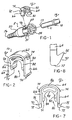
- a snap-on retainer 10 which lockingly couples female and male components 12 and 14, respectively, of a quick connector 16.
- female connector component or element 12 is by way of example only as the female connector component 12 may have any suitable shape typically found in quick connectors.
- a top hat or bearing 34 is mounted in the second stepped bore portion 23 immediately adjacent the end of the first bore portion 21.
- a seal means 30 is also mounted in the second stepped bore portion 23 between one end of the top hat 34 and the third stepped bore portion 25.
- the inner diameter of the first stepped bore portion 21 is sized to slidably receive the outer diameter of the radially enlarged flange or upset bead 18 formed on the male component or fitting 14. Further, the inner diameters of the seal means 30 and the top hat 34 are sized to sealingly engage the outer diameter of the end portion 11 of the male component 14 extending from the radially enlarged flange 18 to the tip end 13 of the male component 14.
- the third stepped bore portion 25 has an inner diameter sized to snugly engage the outer diameter of the end portion 11 of the male component 14 when the male component 14 is fully inserted into the stepped bore 22 as described hereafter.
- the first end 24 of the housing 12 is formed with a pair of opposed, exterior flats 40 and 42.
- the flats 40 and 42 are diametrically opposed on the first end 24 and may be centrally located on each diametrical side of the first end 24.
- the adjacent surfaces of the housing 20 form an opposed pairs of lock surfaces or flats, such as a first flat 44 and a second flat 46.
- a second pair of flats 47 and 49 are formed on the other side of the flats 44 and 46.
- the flats 44 and 46 extend axially a short distance along the first end 24 of the housing 20.
- the opposed surfaces 48 and 50 of the first end 24 of the housing 20 between the flats 44 and 46 and the flats 47 and 48 have a generally arcuate shape as shown in Figs. 3 and 4.
- Apertures 49 and 51 are formed respectively in each surface 48 and 50.
- the apertures 49 and 51 are aligned to form a transverse bore extending through the first end 24 of the housing 20 which is disposed in communication with the first bore portion 21 in the housing 20.
- the retainer 10 shown in Figs. 1, 2-5, and 7-9, is formed of a one-piece body of a suitable plastic, such as polyketone, for example, and has an end wall 62 formed of a generally curved or arcuate shape, by way of example only, and first and second spaced side legs 64 and 66.
- the side legs 64 and 66 extend generally parallel to each other from opposite ends of the end wall 62. Further, each side leg 64 and 66 has an outer end 72, although it is possible to connect the side legs 64 and 66 at a lower portion by an arcuate member.
- a pair of projections 70 extend along the length of the retainer 10 between opposed side edges of the side legs 64 and 66, respectively.
- the projections 70 are located adjacent the outer end 72 of each leg 64 and, by example only 66.
- the projections 70 engage surfaces on the housing 12 to position the retainer 10 in the shipping position shown in Fig. 3, or in the fully inserted, latched position shown in Figs. 4 and 5.
- a pair of outward extending lock tabs or edges 74 are formed adjacent the end wall 62 on each side leg 64 and 66.
- the lock tabs 74 engage notches 76 in the first end 24 the housing 12 when the retainer 10 is fully inserted in the housing 12.
- the lock tabs 74 are offset from the center of the length of each of the side legs 62 and 64 so as to be located generally closer to one side end of the retainer 10 than the opposed side end.
- the retainer 10 includes a radially flange receiving means 80 which is preferably carried as an integral, one-piece part of the retainer 10.
- the radial flange receiving means 80 includes first and second depending arms 82 and 84 which extend from a boss or enlargement 86 integrally formed on the inner surface of the end wall 62 of the retainer 10.
- An inverted, U-shaped slot 88 is formed on the inner surfaces of the arms 82 and 84 and the boss 86 which is sized to snugly conform to the outer diameter of the tubular portion 11 of the male component 14.
- the outer ends 91 of each of the arms 82 and 84 are angled or tapered to act as a guide surface to assist in sliding movement of the arms 82 and 84 over the tubular end 11 of the male component 14.
- each of the arms 82 and 84 extends from one side end contiguous with a first side end 90 of the retainer 10 to an opposed side end which is spaced from a second side end 92 of the retainer 10.
- the recess 94 is positioned to receive the annular flange 18 on the male component 14 only when the male component 14 is fully inserted into the female component or housing 12. This insures a fully seated, sealed connection between the male component 14 and the female component 12 while completely locking the male component 14 in the housing 12.
- the projections 70 on the legs 64 and 66 of the retainer 10 are uniquely formed with an angled hook-like shape terminating in a tip 95.
- the tip 95 is disposed at an acute, upturned angle with respect to the corresponding legs 64 or 66.
- the outer surface of the housing 12 adjacent the first end 24 is formed with a pair of flats 44 and 46 which are disposed at an angle complimentary to the acute angle of the tips 95 on the legs 64 and 66 of the retainer 10. This interlock of the tips 95 with the flats 44 and 46 resists pull out of the retainer 10 from the housing 12.
- the hook shaped tips 95 on the legs 64 and 66 of the retainer 10 in conjunction with the grooves 40' and 42' in the housing 12 also provide, a distinct, "avalanche effect" snap action of the retainer 10 in the housing 12 as shown in Fig. 9.
- the grooves 40' and 42' in the housing 12 are formed in generally planar flat surfaces 100 and 102, respectively. The surfaces 100 and 102 force the ends 72 of the legs 64 and 66 laterally inward toward each other when the retainer 10 is inserted into the housing 12.
- the legs 64 and 66 spring laterally outward in a distinct "avalanche effect" manner.
- the lower ends of the grooves 40' and 42' are angled inward to enable the tips 95 to slide out of the grooves 40' and 42'.
- the retainer 10 can be first be installed on the housing 12 in a shipping or storage position as shown in Fig. 3. In this position, the projections 70 on the side legs 64 and 66 of the retainer 10 snap into and engage the longitudinally extending groves 40' and 42'.
- the annular flange 18 on the male component 14 will not be properly situated within the transverse bore in the housing 12 to slidably receive the recess 94 in the retainer 10. If the annular flange 18 on the male component 14 is at any position other than shown in phantom in Fig. 5, the arms 82 and 84 on the retainer 10 will contact the annular flange 18. Since the spacing between the inner surfaces of the legs 82 and 84 is less than the outer diameter of the annular flange 18, the retainer 10 cannot be moved to the fully inserted position thereby providing an indication of an incomplete seating or mounting of the tip 11 of the male component 14 in the housing 12.
- the snap-on retainer of the present invention also provides a visible indication of a sealed and locked connection between the male and female connector components and insures that the male component is fully inserted into the female component before the retainer can be urged into the fully latched position.
Landscapes
- Engineering & Computer Science (AREA)
- General Engineering & Computer Science (AREA)
- Mechanical Engineering (AREA)
- Quick-Acting Or Multi-Walled Pipe Joints (AREA)
Claims (8)
- Schnellkupplung, die folgendes aufweist:zusammenpassende männliche und weibliche Komponenten (14, 12);wobei die männliche Komponente (14) einen ersten Endteil (11), der in einem Kegel-Ende (13) endet, und einen radial vergrößerten ringförmigen Flansch (18), der von dem Kegel-Ende beabstandet ist, aufweist; die weibliche Komponente (12) folgendes enthält:ein Gehäuse (20) mit einem Durchgangsloch (21), das aus mindestens einem ersten axial verlaufenden Lochteil gebildet ist, der einem offenen ersten Ende (24) des Gehäuses zur Aufnahme der männlichen Komponente darin gegenüber liegt;erste und zweite gegenüberliegende, ausgerichtete Öffnungen (49, 51), die in dem Gehäuse in Querverbindung mit dem ersten Lochteil (23) ausgebildet sind und ein Querloch bilden, das durch das Gehäuse verläuft; undeine Halteeinrichtung (10), die durch die erste und zweite Öffnung (49, 51) in dem Gehäuse zur lösbaren Verriegelung der männlichen und weiblichen Komponenten hindurchschiebbar ist,wobei die Halteeinrichtung einen Körper mit einer Endwand (62) und ersten und zweiten beabstandeten Schenkeln (64, 66), die sich von der Endwand aus erstrecken und durch die Öffnungen (49, 51) hindurchschiebbar sind, aufweist, wobei der erste und zweite Schenkel jeweils gegenüberliegende erste und zweite Seitenkanten aufweisen, gekennzeichnet durch:erste und zweite Arme (82, 84), die an dem Körper innerhalb des ersten bzw. zweiten Schenkels ausgebildet sind, wobei der erste und zweite Arm voneinander um einen Abstand beabstandet sind, der kleiner ist als ein Außendurchmesser des ringförmigen Flansches (18) der männlichen Komponente;wobei sich der erste und zweite Arm (82, 84) zwischen der ersten und zweiten Seitenkante des ersten und zweiten Schenkels (65, 65) auf einer Distanz erstrecken, die kleiner ist als eine Länge des ersten und zweiten Schenkels zwischen der ersten und zweiten Seitenkante des ersten und zweiten Schenkels, unter Bildung einer Aussparung innerhalb des ersten und zweiten Schenkels zur Aufnahme des ringförmigen Flansches an der männlichen Komponente, nur wenn die männliche Komponente in der weiblichen Komponente vollkommen fest sitzt; undVorsprünge (70), die an dem ersten und zweiten Schenkel in Form von nach außen gewinkelten Haken (95) ausgebildet und lösbar in eine Außenfläche (44, 46) des Gehäuses einrastbar sind, nachdem der Halter vollständig in das Querloch in dem Gehäuse eingeschoben ist und die Enden der Schenkel durch eine der ersten und zweiten Öffnungen in dem Gehäuse nach außen ragen.
- Schnellkupplung nach Anspruch 1, wobei: die Haken (95) aus einem Endteil (72) geformt sind; und eine Spitze (95) vom Endteil gewinkelt nach außen verläuft.
- Schnellkupplung nach Anspruch 2, wobei die Spitze (95) zu dem gegenüberliegenden Schenkel des ersten und zweiten Schenkels in einem spitzen Winkel liegt.
- Schnellkupplung nach Anspruch 3, die außerdem folgendes aufweist mindestens eine Flachstelle (44, 46), die an dem Gehäuse ausgebildet ist und in einem zu dem Winkel der Spitze an einem der ersten und zweiten Schenkel des Halters komplementären Winkel liegt.
- Schnellkupplung nach Anspruch 3, die außerdem folgendes aufweist:wobei die Nuten eine Aussparung (96) aufweisen, in die die Haken unter Verriegelung des Halters in einer teilweise in das Gehäuse eingeschobenen Position einrastbar sind.ein Paar von Nuten (40', 42'), die in dem ersten Lochteil des Gehäuses ausgebildet sind, wobei die Nuten von dem ersten offenen Ende des Gehäuses axial verlaufen;
- Schnellkupplung nach Anspruch 5, wobei:jede Aussparung (40', 42') eine Innenkante in einem Winkel komplementär zu dem Winkel an der Spitze der Haken aufweist.
- Schnellkupplung nach Anspruch 1, die außerdem folgendes aufweist:wobei die Kerbe innerhalb der einen der Öffnungen in dem Gehäuse zur Aufnahme der Nase an dem Halter in nur einer Orientierung des Halters in dem Querloch in dem Gehäuse mittelpunktsverschoben ist.mindestens eine Nase (74), die von einem der ersten und der zweiten Schenkel des Körpers seitlich nach außen verläuft;eine Kerbe (76), die im ersten Ende des Gehäuses gegenüber einer der Öffnungen in dem ersten Ende des Gehäuses zur Aufnahme der Nase ausgebildet ist; und
- Schnellkupplung nach Anspruch 1, die außerdem folgendes aufweist:eine von dem ersten und zweiten Schenkel des Körpers und zwischen einer der Seitenkanten des ersten und zweiten Schenkels und des ersten und zweiten Arms an dem Körper materiell gebildete Aussparung, wobei die Aussparung und eine Endfläche des ersten und zweiten Arms eine Radialflansch-Einrastfläche zur Aufnahme des ringförmigen Flansches an der männlichen Komponente bilden und einen vollständigen Einschub des Halters in das Querloch in dem Gehäuse nur zulassen, wenn die männliche Komponente vollständig in den in dem Gehäuse axial verlaufenden Lochteil eingeschoben ist.
Applications Claiming Priority (3)
| Application Number | Priority Date | Filing Date | Title |
|---|---|---|---|
| US08/839,155 US5951063A (en) | 1995-06-07 | 1997-04-23 | Quick connector with snap-on retainer having enhanced engagement |
| US839155 | 1997-04-23 | ||
| PCT/US1998/008179 WO1998048209A1 (en) | 1997-04-23 | 1998-04-23 | Quick connector with snap-on retainer having enhanced engagement |
Publications (2)
| Publication Number | Publication Date |
|---|---|
| EP0990100A1 EP0990100A1 (de) | 2000-04-05 |
| EP0990100B1 true EP0990100B1 (de) | 2002-07-10 |
Family
ID=25278992
Family Applications (1)
| Application Number | Title | Priority Date | Filing Date |
|---|---|---|---|
| EP98919855A Expired - Lifetime EP0990100B1 (de) | 1997-04-23 | 1998-04-23 | Schnellkupplung mit schnappverriegelungshalter zur verbesserten befestigung |
Country Status (4)
| Country | Link |
|---|---|
| US (1) | US5951063A (de) |
| EP (1) | EP0990100B1 (de) |
| DE (1) | DE69806482T2 (de) |
| WO (1) | WO1998048209A1 (de) |
Families Citing this family (60)
| Publication number | Priority date | Publication date | Assignee | Title |
|---|---|---|---|---|
| JP4462671B2 (ja) * | 1998-09-17 | 2010-05-12 | 株式会社東郷製作所 | 管継手 |
| DE29916385U1 (de) * | 1999-09-17 | 1999-12-23 | Alfred Kärcher GmbH & Co, 71364 Winnenden | Handspritzpistole für ein Hochdruckreinigungsgerät |
| DE19946260C1 (de) * | 1999-09-27 | 2001-01-11 | Itt Mfg Enterprises Inc | Schnellkupplung für Schläuche oder Rohrleitungen in Kraftfahrzeugen |
| DE19963368A1 (de) * | 1999-12-28 | 2001-07-12 | Itt Mfg Enterprises Inc | Schnellkupplung für Schläuche oder Rohrleitungen mit erhöhtem Diffusionswiderstand |
| US6371529B1 (en) | 1999-12-28 | 2002-04-16 | Itt Manufacturing Enterprises, Inc. | Quick connector with swivelable retainer housing |
| US6612622B2 (en) | 2000-04-06 | 2003-09-02 | Itt Manufacturing Enterprises, Inc. | Rotatable quick connector |
| DE10024303B4 (de) * | 2000-05-17 | 2005-09-08 | Rasmussen Gmbh | Aufnahme-Kupplungsvorrichtung einer Steckkupplung und Steckkupplung mit der Aufnahme-Kupplungsvorrichtung |
| US6520546B2 (en) | 2000-12-27 | 2003-02-18 | Itt Manufacturing Enterprises, Inc. | Quick connector release tool |
| US6557903B2 (en) | 2000-12-27 | 2003-05-06 | Itt Manufacturing Enterprises, Inc. | Twist lock high pressure quick connector |
| US20030137148A1 (en) * | 2000-12-27 | 2003-07-24 | Andre Michael J. | Fluid quick connector with non-rotation conduit engaging ribs |
| US6431612B1 (en) * | 2000-12-28 | 2002-08-13 | Itt Manufacturing Enterprises, Inc. | Air flow conduit quick connector |
| JP3871885B2 (ja) * | 2001-01-09 | 2007-01-24 | 三桜工業株式会社 | 配管用継手 |
| JP3958028B2 (ja) * | 2001-01-15 | 2007-08-15 | 三桜工業株式会社 | 配管用継手 |
| US6641060B2 (en) * | 2001-06-28 | 2003-11-04 | Moen Incorporated | Modular kitchen deck side spray |
| US6550815B2 (en) | 2001-08-14 | 2003-04-22 | Itt Manufacturing Enterprises, Inc. | Coaxial quick connector |
| US20050179257A1 (en) * | 2001-10-10 | 2005-08-18 | Flex Technologies, Inc. | Connector and method of manufacture |
| US6637779B2 (en) * | 2001-10-18 | 2003-10-28 | Itt Manufacturing Enterprises, Inc. | Fluid quick connector with grooved endform |
| US6755675B2 (en) | 2001-11-12 | 2004-06-29 | Itt Manufacturing Enterprises, Inc. | Fluid quick connector with secure electrical ground contact |
| US6805383B2 (en) | 2001-11-12 | 2004-10-19 | Itt Manufacturing Enterprises, Inc. | Fluid quick connector with secure electrical contact |
| US6892871B2 (en) * | 2002-03-11 | 2005-05-17 | Cummins-Allison Corp. | Sensor and method for discriminating coins of varied composition, thickness, and diameter |
| US7029036B2 (en) * | 2004-03-09 | 2006-04-18 | Itt Manufacturing Enterprises, Inc. | Rotatable two part quick connection |
| US8113547B2 (en) * | 2002-03-22 | 2012-02-14 | Cooper Standard Automotive Inc. | Snap mount fluid quick connector |
| US6905143B2 (en) * | 2002-03-22 | 2005-06-14 | Itt Manufacturing Enterprises, Inc. | Fluid conduit quick connector and stuffer pack |
| US6634679B1 (en) * | 2002-04-17 | 2003-10-21 | Itt Manufacturing Enterprises, Inc. | Fluid quick connector with retention clip for flangeless endforms |
| KR20040008386A (ko) * | 2002-07-18 | 2004-01-31 | 한라공조주식회사 | 퀵커플러 |
| US6637781B1 (en) * | 2002-10-07 | 2003-10-28 | International Engine Intellectual Property Company, L.L.C. | Coupling |
| US6866303B2 (en) * | 2002-10-16 | 2005-03-15 | Itt Manufacturing Enterprises, Inc. | Low profile fluid quick connector |
| US6757950B2 (en) | 2002-11-15 | 2004-07-06 | Itt Manufacturing Enterprises, Inc. | Rotatable quick connector stuffer pin |
| JP4198487B2 (ja) * | 2003-02-20 | 2008-12-17 | 三桜工業株式会社 | クイックコネクタの防塵キャップ |
| JP4271516B2 (ja) * | 2003-07-10 | 2009-06-03 | 三桜工業株式会社 | クイックコネクター |
| US6832785B1 (en) | 2003-07-21 | 2004-12-21 | Itt Manufacturing Enterprises, Inc. | Spin welded fluid coupling |
| DE602004030527D1 (de) * | 2003-10-22 | 2011-01-27 | Togo Seisakusho Kk | Rohrverbindung |
| US7055869B2 (en) * | 2004-01-27 | 2006-06-06 | Itt Manufacturing Enterprises, Inc. | False insertion protection top hat for fluid quick connectors |
| DE102004020505B4 (de) * | 2004-04-22 | 2009-05-28 | A. Raymond Et Cie | Kupplung für ein Fluidleitungssystem |
| US7314209B2 (en) | 2004-08-06 | 2008-01-01 | Cooper Standard Automotive, Inc. | Stub out fluid quick connector with shut off valve interface |
| US7121592B2 (en) | 2004-09-10 | 2006-10-17 | Itt Manufacturing Enterprises, Inc. | Fluid quick connect with adjustable flow control valve |
| DE102004062887B3 (de) * | 2004-12-27 | 2005-10-13 | A. Raymond & Cie | Kupplung |
| US20060146877A1 (en) * | 2004-12-31 | 2006-07-06 | Bea Systems, Inc. | Multipool using automatically maintained active connection pool list |
| JP4623371B2 (ja) * | 2005-05-13 | 2011-02-02 | 東海ゴム工業株式会社 | クイックコネクタ |
| US7118403B1 (en) * | 2005-10-31 | 2006-10-10 | International Engine Intellectual Property Company, Llc | Connector clip and method |
| US20070222214A1 (en) * | 2006-03-24 | 2007-09-27 | Gary Klinger | Spin weld water attachments |
| US20070241560A1 (en) * | 2006-04-18 | 2007-10-18 | Malone David S | Coaxial quick connector |
| FR2903164B1 (fr) * | 2006-06-30 | 2008-09-26 | Tokai Rubber Ind Ltd | Raccord rapide |
| DE102006047267B4 (de) * | 2006-10-04 | 2010-02-04 | A. Raymond Et Cie | Kupplungsteil für eine Fluidleitungskupplung |
| DE102007028061A1 (de) * | 2007-06-19 | 2008-12-24 | Fränkische Rohrwerke Gebr. Kirchner GmbH + Co. KG | Kupplungssystem |
| US8869820B2 (en) * | 2007-11-14 | 2014-10-28 | The Ames Companies, Inc. | Poly-metal hose reel water system |
| DE102008019979B3 (de) * | 2008-04-21 | 2009-10-01 | Futuree Fuel Cell Solutions Gmbh | Energieversorgungsmodul und Stromschrank |
| DK2243505T3 (en) * | 2009-04-23 | 2018-04-30 | Bayer Healthcare Llc | Spraying devices and methods of producing spraying devices |
| CH704182A2 (de) * | 2010-12-01 | 2012-06-15 | Agro Ag | Haltevorrichtung zum halten eines kabels. |
| AT511045A1 (de) * | 2011-01-28 | 2012-08-15 | Blum Gmbh Julius | Möbelteil mit einer drehmomentübertragenden welle |
| JP5901184B2 (ja) * | 2011-09-02 | 2016-04-06 | 株式会社ニフコ | コネクタ用プラグ |
| US8371620B1 (en) | 2011-09-22 | 2013-02-12 | Tsai-Chen Yang | Quick connector |
| US9022433B2 (en) | 2012-03-21 | 2015-05-05 | Tsai-Chen Yang | Quick connector adapted for a male adapter to connect thereto |
| US8764068B2 (en) | 2012-05-10 | 2014-07-01 | Moen Incorporated | Quick connect coupling with retention feature |
| EP2796758B1 (de) * | 2013-04-23 | 2016-12-07 | TI Automotive (Fuldabrück) GmbH | Kupplung |
| US11187360B2 (en) | 2014-10-23 | 2021-11-30 | Idex Health & Science Llc | Fluidic connector assembly for quick connect/disconnect |
| DE102016109051A1 (de) * | 2015-10-21 | 2017-04-27 | Voss Automotive Gmbh | Steckverbinder für Medienleitungen |
| JP7035030B2 (ja) | 2016-06-13 | 2022-03-14 | アイデックス ヘルス アンド サイエンス エルエルシー | 迅速接続/接続解除のための流体接続アセンブリ |
| DK180026B1 (en) * | 2018-03-12 | 2020-01-24 | Mbh-International A/S | A flexible double lumen tube and a tube coupling system for same |
| US20240124264A1 (en) | 2022-10-13 | 2024-04-18 | Nickolas Brands, Llc | Hose reel enclosure system |
Family Cites Families (55)
| Publication number | Priority date | Publication date | Assignee | Title |
|---|---|---|---|---|
| US1298878A (en) * | 1917-03-01 | 1919-04-01 | Harold P Brown | Conduit. |
| US1893979A (en) * | 1932-02-12 | 1933-01-10 | John P Barrere | Cleaning device for waste or drain pipes |
| US2021241A (en) * | 1934-12-24 | 1935-11-19 | Mall Arthur William | Quick detachable coupling |
| US2423726A (en) * | 1945-06-07 | 1947-07-08 | Prata Joe | Quick breaking union for pipe ends |
| US3245702A (en) * | 1965-08-05 | 1966-04-12 | James M Smith | Leakproof joint |
| US3560027A (en) * | 1967-02-20 | 1971-02-02 | Gra Tec Inc | Coupling assembly |
| US3794057A (en) * | 1972-06-26 | 1974-02-26 | Textron Inc | Safety breakaway fluid coupling |
| US4244608A (en) * | 1979-03-05 | 1981-01-13 | The Gates Rubber Company | Female coupling with staple lock |
| US4524995A (en) * | 1980-10-29 | 1985-06-25 | Proprietary Technology, Inc. | Swivelable quick connector assembly |
| US4936544A (en) * | 1980-10-29 | 1990-06-26 | Proprietary Technology, Inc. | Swivelable quick connector assembly |
| US4423892A (en) * | 1980-10-29 | 1984-01-03 | Bartholomew Donald D | Swivelable quick connector assembly |
| US4948175A (en) * | 1980-10-29 | 1990-08-14 | Proprietary Technology, Inc. | Swivelable quick connector assembly |
| US4526411A (en) * | 1980-10-29 | 1985-07-02 | Proprietary Technology, Inc. | Swivelable quick connector assembly |
| US4431218A (en) * | 1982-02-05 | 1984-02-14 | Dayco Corporation | Fluid coupling and method of making same |
| US4433861A (en) * | 1982-02-16 | 1984-02-28 | Stefan Kreczik | Arrangement for connecting two pipe ends |
| US4561682A (en) * | 1982-09-03 | 1985-12-31 | Rain Bird Consumer Products Mfg. Corp. | Quick connect coupling |
| US4591192A (en) * | 1984-03-15 | 1986-05-27 | Rain Bird Consumer Products Mfg. Corp. | Quick connect coupling |
| US4650221A (en) * | 1985-02-14 | 1987-03-17 | Caillouet Jr Stanford J | Quick connect coupling safety clamp system |
| SU1404747A1 (ru) * | 1985-03-20 | 1988-06-23 | Предприятие П/Я Р-6500 | Быстроразъемное соединение трубопроводов |
| SU1317266A1 (ru) * | 1986-01-02 | 1987-06-15 | Владимирский Научно-Исследовательский Конструкторско-Технологический Институт Тракторных И Комбайновых Двигателей | Приспособление дл тарировки электрического торсиографа |
| US4874174A (en) * | 1987-03-05 | 1989-10-17 | Aisin Seiki Kabushiki Kaisha | Tube connecting unit |
| US4792163A (en) * | 1987-05-13 | 1988-12-20 | Baxter Travenol Laboratories, Inc. | Secondary lock for medical tube coupling |
| US4787770A (en) * | 1987-07-07 | 1988-11-29 | Buford Lewis | Locking device for air hose coupling devices of tractor trailers |
| DE3739745C1 (en) * | 1987-11-24 | 1988-11-24 | Helmut Schuchardt | Connecting and joining sleeve for flexible tubes |
| JP2691550B2 (ja) * | 1988-03-01 | 1997-12-17 | 臼井国際産業株式会社 | 細径配管接続用コネクター |
| JPH0538317Y2 (de) * | 1988-03-03 | 1993-09-28 | ||
| US4869534A (en) * | 1988-09-26 | 1989-09-26 | Huron Products Corporation | Swivelable quick connector |
| US4925217A (en) * | 1988-10-24 | 1990-05-15 | Huron Products Corporation | Quick connector with visual checking method |
| FR2649182B1 (fr) * | 1989-07-03 | 1991-10-11 | Chaffoteaux Et Maury | Perfectionnements aux raccords de tuyauteries |
| US5069424A (en) * | 1990-10-17 | 1991-12-03 | Itt Corporation | Quick connector |
| US5102313A (en) * | 1990-11-16 | 1992-04-07 | Alfred Teves Gmbh | Coupler particularly suitable for use as a fuel sender coupling device |
| FR2669709B1 (fr) * | 1990-11-27 | 1993-02-19 | Hutchinson Sa | Dispositif de raccord, notamment pour l'assemblage d'une durite a un echangeur de chaleur de vehicule automobile. |
| US5211427A (en) * | 1990-12-22 | 1993-05-18 | Usui Kokusai Sangyo Kaisha Ltd. | Piping connector |
| US5152555A (en) * | 1991-03-26 | 1992-10-06 | Itt Corporation | Quick connect insertion indicator clip |
| US5226679A (en) * | 1991-05-16 | 1993-07-13 | Itt Corporation | Quick connect insertion indicator |
| US5178424A (en) * | 1991-07-01 | 1993-01-12 | Itt Corporation | Pop-off quick connect indicator |
| US5213376A (en) * | 1991-09-03 | 1993-05-25 | Itt Corporation | Squeeze-to-release quick connector |
| US5277402A (en) * | 1991-10-08 | 1994-01-11 | Itt Corporation | Quick connect fluid coupling with check valve |
| US5297818A (en) * | 1991-12-18 | 1994-03-29 | Itt Corporation | Retainer for pop-top indicator |
| WO1993014341A1 (en) * | 1992-01-17 | 1993-07-22 | Huron Products Industries Inc. | Tubing connector |
| US5423577A (en) * | 1992-01-17 | 1995-06-13 | Bundy Corporation | Tubing connector |
| US5275443A (en) * | 1992-09-15 | 1994-01-04 | Itt Corporation | Sliding collar quick connect |
| US5354102A (en) * | 1993-02-03 | 1994-10-11 | Itt Corporation | Quick connector |
| US5360237A (en) * | 1993-03-23 | 1994-11-01 | Itt Corporation | Quick connector |
| US5401063A (en) * | 1993-07-19 | 1995-03-28 | Enhanced Applications, L.C. | Primary/secondary retainer for beaded/flared tubing |
| US5405175A (en) * | 1993-09-24 | 1995-04-11 | Siemens Automotive L.P. | Clip attachment of fuel tube to fuel rail |
| US5348353A (en) * | 1993-12-02 | 1994-09-20 | Chrysler Corporation | Positive quick-connect tube locking construction with preassembly retention of spring keeper |
| US5452924A (en) * | 1994-06-20 | 1995-09-26 | Bundy Corporation | Manually operable release mechanism for quick connector |
| US5730481A (en) * | 1994-11-04 | 1998-03-24 | Itt Automotive, Inc. | Quick connector with snap-on retainer |
| US5542716A (en) * | 1994-11-04 | 1996-08-06 | Itt Corporation | Quick connector with snap-on retainer |
| US5799986A (en) * | 1994-12-21 | 1998-09-01 | Flex Technologies, Inc. | Connector assembly and method of manufacture |
| US5586792A (en) * | 1995-02-21 | 1996-12-24 | Bundy Corporation | Quick connector with integral release mechanism |
| US5683117A (en) * | 1995-12-14 | 1997-11-04 | Flex Technologies, Inc. | Retainer clip for a connector |
| US5782502A (en) * | 1995-12-29 | 1998-07-21 | Itt Automotive, Inc. | Radial-release quick connector |
| US5863077A (en) * | 1996-12-20 | 1999-01-26 | Itt Automotive, Inc. | Quick connector with snap-on frangible retainer |
-
1997
- 1997-04-23 US US08/839,155 patent/US5951063A/en not_active Expired - Lifetime
-
1998
- 1998-04-23 EP EP98919855A patent/EP0990100B1/de not_active Expired - Lifetime
- 1998-04-23 WO PCT/US1998/008179 patent/WO1998048209A1/en not_active Ceased
- 1998-04-23 DE DE69806482T patent/DE69806482T2/de not_active Expired - Lifetime
Also Published As
| Publication number | Publication date |
|---|---|
| US5951063A (en) | 1999-09-14 |
| DE69806482D1 (de) | 2002-08-14 |
| WO1998048209A1 (en) | 1998-10-29 |
| EP0990100A1 (de) | 2000-04-05 |
| DE69806482T2 (de) | 2003-03-06 |
Similar Documents
| Publication | Publication Date | Title |
|---|---|---|
| EP0990100B1 (de) | Schnellkupplung mit schnappverriegelungshalter zur verbesserten befestigung | |
| EP0944797B1 (de) | Schnellkupplung mit abbrechbaren schnappverriegelungshalter | |
| US6293596B1 (en) | Quick connector with after incident indicator clip | |
| US5730481A (en) | Quick connector with snap-on retainer | |
| US5542716A (en) | Quick connector with snap-on retainer | |
| US6520546B2 (en) | Quick connector release tool | |
| US6634679B1 (en) | Fluid quick connector with retention clip for flangeless endforms | |
| US7390029B2 (en) | Quick connector | |
| EP1304521B1 (de) | Schnellverbindung für Flüssigkeiten mit einem in radialer Richtung bewegbaren Verriegelungselement | |
| US5395140A (en) | Secondary latch and indicator for fluid coupling | |
| US4979765A (en) | Swivelable quick connector assembly | |
| EP0795101B1 (de) | Schnellkupplung mit positiver verriegelung | |
| EP1272789B1 (de) | Drehbare schnellkupplung | |
| EP0788590B1 (de) | Entriegelungselement für schnellkupplungen | |
| US6757950B2 (en) | Rotatable quick connector stuffer pin | |
| EP1495252A1 (de) | Fluidleitungsschnellverbinder und stopfpackung | |
| US6805383B2 (en) | Fluid quick connector with secure electrical contact | |
| EP1559945B1 (de) | Lagerbuchse zum Schutz vor falschem Einstecken für Fluid-Schnellverbinder | |
| US6802491B1 (en) | Fluid shut off valve cartridge with quick connection | |
| EP1310722A2 (de) | Schnellverbindung für Flüssigkeiten mit sicherem, elektrischem Erdungskontakt | |
| US5797634A (en) | Quick connect fluid coupling having attachment | |
| EP1724511B1 (de) | Schnellverbinder mit Halteelement | |
| EP0824646A1 (de) | Schnellkupplung mit ring zur sicherung der korrekten verbindung |
Legal Events
| Date | Code | Title | Description |
|---|---|---|---|
| PUAI | Public reference made under article 153(3) epc to a published international application that has entered the european phase |
Free format text: ORIGINAL CODE: 0009012 |
|
| 17P | Request for examination filed |
Effective date: 19991123 |
|
| AK | Designated contracting states |
Kind code of ref document: A1 Designated state(s): DE ES FR GB IT NL SE |
|
| 17Q | First examination report despatched |
Effective date: 20001212 |
|
| GRAG | Despatch of communication of intention to grant |
Free format text: ORIGINAL CODE: EPIDOS AGRA |
|
| GRAG | Despatch of communication of intention to grant |
Free format text: ORIGINAL CODE: EPIDOS AGRA |
|
| GRAH | Despatch of communication of intention to grant a patent |
Free format text: ORIGINAL CODE: EPIDOS IGRA |
|
| GRAH | Despatch of communication of intention to grant a patent |
Free format text: ORIGINAL CODE: EPIDOS IGRA |
|
| GRAA | (expected) grant |
Free format text: ORIGINAL CODE: 0009210 |
|
| AK | Designated contracting states |
Kind code of ref document: B1 Designated state(s): DE ES FR GB IT NL SE |
|
| PG25 | Lapsed in a contracting state [announced via postgrant information from national office to epo] |
Ref country code: NL Free format text: LAPSE BECAUSE OF FAILURE TO SUBMIT A TRANSLATION OF THE DESCRIPTION OR TO PAY THE FEE WITHIN THE PRESCRIBED TIME-LIMIT Effective date: 20020710 Ref country code: IT Free format text: LAPSE BECAUSE OF FAILURE TO SUBMIT A TRANSLATION OF THE DESCRIPTION OR TO PAY THE FEE WITHIN THE PRESCRIBED TIME-LIMIT;WARNING: LAPSES OF ITALIAN PATENTS WITH EFFECTIVE DATE BEFORE 2007 MAY HAVE OCCURRED AT ANY TIME BEFORE 2007. THE CORRECT EFFECTIVE DATE MAY BE DIFFERENT FROM THE ONE RECORDED. Effective date: 20020710 |
|
| REG | Reference to a national code |
Ref country code: GB Ref legal event code: FG4D |
|
| REF | Corresponds to: |
Ref document number: 69806482 Country of ref document: DE Date of ref document: 20020814 |
|
| PG25 | Lapsed in a contracting state [announced via postgrant information from national office to epo] |
Ref country code: SE Free format text: LAPSE BECAUSE OF FAILURE TO SUBMIT A TRANSLATION OF THE DESCRIPTION OR TO PAY THE FEE WITHIN THE PRESCRIBED TIME-LIMIT Effective date: 20021010 |
|
| ET | Fr: translation filed | ||
| NLV1 | Nl: lapsed or annulled due to failure to fulfill the requirements of art. 29p and 29m of the patents act | ||
| PG25 | Lapsed in a contracting state [announced via postgrant information from national office to epo] |
Ref country code: ES Free format text: LAPSE BECAUSE OF FAILURE TO SUBMIT A TRANSLATION OF THE DESCRIPTION OR TO PAY THE FEE WITHIN THE PRESCRIBED TIME-LIMIT Effective date: 20030130 |
|
| PLBE | No opposition filed within time limit |
Free format text: ORIGINAL CODE: 0009261 |
|
| STAA | Information on the status of an ep patent application or granted ep patent |
Free format text: STATUS: NO OPPOSITION FILED WITHIN TIME LIMIT |
|
| 26N | No opposition filed |
Effective date: 20030411 |
|
| REG | Reference to a national code |
Ref country code: FR Ref legal event code: PLFP Year of fee payment: 18 |
|
| REG | Reference to a national code |
Ref country code: FR Ref legal event code: PLFP Year of fee payment: 19 |
|
| REG | Reference to a national code |
Ref country code: FR Ref legal event code: PLFP Year of fee payment: 20 |
|
| PGFP | Annual fee paid to national office [announced via postgrant information from national office to epo] |
Ref country code: FR Payment date: 20170313 Year of fee payment: 20 |
|
| PGFP | Annual fee paid to national office [announced via postgrant information from national office to epo] |
Ref country code: DE Payment date: 20170420 Year of fee payment: 20 Ref country code: GB Payment date: 20170419 Year of fee payment: 20 |
|
| REG | Reference to a national code |
Ref country code: DE Ref legal event code: R071 Ref document number: 69806482 Country of ref document: DE |
|
| REG | Reference to a national code |
Ref country code: GB Ref legal event code: PE20 Expiry date: 20180422 |
|
| PG25 | Lapsed in a contracting state [announced via postgrant information from national office to epo] |
Ref country code: GB Free format text: LAPSE BECAUSE OF EXPIRATION OF PROTECTION Effective date: 20180422 |