EP0989943B1 - Paper sack - Google Patents
Paper sack Download PDFInfo
- Publication number
- EP0989943B1 EP0989943B1 EP98930874A EP98930874A EP0989943B1 EP 0989943 B1 EP0989943 B1 EP 0989943B1 EP 98930874 A EP98930874 A EP 98930874A EP 98930874 A EP98930874 A EP 98930874A EP 0989943 B1 EP0989943 B1 EP 0989943B1
- Authority
- EP
- European Patent Office
- Prior art keywords
- sack
- perforations
- wall
- paper
- vapour barrier
- Prior art date
- Legal status (The legal status is an assumption and is not a legal conclusion. Google has not performed a legal analysis and makes no representation as to the accuracy of the status listed.)
- Expired - Lifetime
Links
- 230000004888 barrier function Effects 0.000 claims description 37
- 239000011505 plaster Substances 0.000 claims description 21
- 239000000843 powder Substances 0.000 claims description 17
- 239000011248 coating agent Substances 0.000 claims description 7
- 238000000576 coating method Methods 0.000 claims description 7
- 238000000034 method Methods 0.000 claims description 4
- 238000004806 packaging method and process Methods 0.000 claims description 2
- 239000000123 paper Substances 0.000 description 34
- 238000003860 storage Methods 0.000 description 11
- 239000004698 Polyethylene Substances 0.000 description 6
- 239000010410 layer Substances 0.000 description 6
- -1 polyethylene Polymers 0.000 description 6
- 229920000573 polyethylene Polymers 0.000 description 6
- 230000000052 comparative effect Effects 0.000 description 5
- 238000012360 testing method Methods 0.000 description 5
- XLYOFNOQVPJJNP-UHFFFAOYSA-N water Substances O XLYOFNOQVPJJNP-UHFFFAOYSA-N 0.000 description 5
- 239000002655 kraft paper Substances 0.000 description 4
- 238000013022 venting Methods 0.000 description 4
- 238000004519 manufacturing process Methods 0.000 description 3
- 239000002356 single layer Substances 0.000 description 3
- 238000004026 adhesive bonding Methods 0.000 description 2
- 230000006866 deterioration Effects 0.000 description 2
- 239000000428 dust Substances 0.000 description 2
- 230000015572 biosynthetic process Effects 0.000 description 1
- 230000009172 bursting Effects 0.000 description 1
- 239000004568 cement Substances 0.000 description 1
- 239000002131 composite material Substances 0.000 description 1
- 238000005520 cutting process Methods 0.000 description 1
- 238000011161 development Methods 0.000 description 1
- 230000002708 enhancing effect Effects 0.000 description 1
- 239000010419 fine particle Substances 0.000 description 1
- 239000000463 material Substances 0.000 description 1
- 239000002245 particle Substances 0.000 description 1
- 229920000642 polymer Polymers 0.000 description 1
- 238000004321 preservation Methods 0.000 description 1
- 230000000750 progressive effect Effects 0.000 description 1
- 238000010561 standard procedure Methods 0.000 description 1
- 238000010998 test method Methods 0.000 description 1
Images

Classifications
-
- B—PERFORMING OPERATIONS; TRANSPORTING
- B65—CONVEYING; PACKING; STORING; HANDLING THIN OR FILAMENTARY MATERIAL
- B65D—CONTAINERS FOR STORAGE OR TRANSPORT OF ARTICLES OR MATERIALS, e.g. BAGS, BARRELS, BOTTLES, BOXES, CANS, CARTONS, CRATES, DRUMS, JARS, TANKS, HOPPERS, FORWARDING CONTAINERS; ACCESSORIES, CLOSURES, OR FITTINGS THEREFOR; PACKAGING ELEMENTS; PACKAGES
- B65D31/00—Bags or like containers made of paper and having structural provision for thickness of contents
- B65D31/04—Bags or like containers made of paper and having structural provision for thickness of contents with multiple walls
-
- B—PERFORMING OPERATIONS; TRANSPORTING
- B65—CONVEYING; PACKING; STORING; HANDLING THIN OR FILAMENTARY MATERIAL
- B65D—CONTAINERS FOR STORAGE OR TRANSPORT OF ARTICLES OR MATERIALS, e.g. BAGS, BARRELS, BOTTLES, BOXES, CANS, CARTONS, CRATES, DRUMS, JARS, TANKS, HOPPERS, FORWARDING CONTAINERS; ACCESSORIES, CLOSURES, OR FITTINGS THEREFOR; PACKAGING ELEMENTS; PACKAGES
- B65D33/00—Details of, or accessories for, sacks or bags
- B65D33/01—Ventilation or drainage of bags
Definitions
- This invention relates to multi-wall paper sacks, and to powder products packaged in such sacks.
- Some powder products notably plaster and cement, react with water when used, and require protection from atmospheric moisture during storage.
- a vapour barrier between the walls of the sack for instance a coating of polyethylene on the outer surface of an inner wall or on the inner surface of an outer wall.
- US 2,340,546 describes a multi-wall paper sack for a powder product shaped to provide front and back faces joined at the sides of the sack and joined by binding strips at the top and bottom ends of the sack.
- One or more walls of this multi-wall paper sack is formed from paper which has been water-proofed and thereby rendered impervious to air but which has been perforated with small holes which allow the passage of air.
- the present invention provides a multi-wall paper sack for a powder product shaped to provide a pair of broad faces, i.e front and back faces, joined by side faces which are narrower than the front and back and also joined at top and bottom ends, which sack has a paper inner wall, which is porous, surrounded by a vapour barrier which is separate from the paper inner wall, and a paper outer wall, on either or both of the front and back faces there being perforations through the vapour barrier with an average density of perforation over the said face of at least 0.3 holes per cm 2 , better at least 0.5 or 0.7 holes per cm 2 , wherein the number of perforations (if any) through the vapour barrier at each side face of the sack is sufficiently small that the average density thereof over the side faces is less than 0.1 holes per cm 2 .
- the total number of perforations through the vapour barrier on the front or back face of the sack will usually exceed 500 and may exceed 1000.
- the vapour barrier could be provided by means of a separate layer in between the innermost paper wall and the paper outer wall. More conveniently however it is provided as a coating on the inside surface of the paper outer wall and the perforations through the vapour barrier are perforations through the outer paper wall and the vapour barrier.
- porous paper innermost wall appears to provide effective passage of air venting from the interior of the bag, yet is a barrier to dust, allowing the perforations through the outer wall to remain open.
- Sacks in accordance with this invention may be utilised when filling of the sacks takes place through a nozzle inserted into an aperture provided at an otherwise closed end of a sack, and the filling of a sack is carried out in less than 12 seconds, and possibly in shorter times such as less than 10 or less than 8 seconds.
- this invention provides a method of packaging a powder product, which comprises providing sacks as set forth above which include a filling aperture, inserting a filling nozzle into that aperture of a sack, and filling the sack.
- the time for filling does not exceed 12 seconds.
- the total number of perforations through the vapour barrier at each side wall is not greater than 50 at most. Because perforation of the side walls is kept to a low level most of the filled sacks in a stack will have the perforations through the front and back faces blocked by other sacks above and below them in the stack. For the same reason, it is preferred that on each perforated face of the sack, the perforations are confined to a band which is spaced inwardly from the side edges.
- perforations are substantially confined to the front face or the back face of the sack, but not both of them. It is then possible to stack the filled sacks so that every sack in the stack has its single perforated face lying against another sack. Alternatively a vapour barrier can be provided at the face of the stack where perforations would otherwise be exposed.
- this invention provides the use of a sack as above to protect a powder product from moisture, thus enhancing the storage stability of a moisture-sensitive powder product packaged therein.
- the inner wall of a sack must be porous. Almost any paper which does not carry a vapour barrier is porous to some extent. Preferably however, the paper has an air resistance (Gurley) of not more than 15 seconds better not more than 10 seconds.
- Gurley air resistance
- the Gurley method for testing the air permeance of paper is a standard method in which a test piece of paper blocks the flow of air from a cylinder as a second cylinder slides within it. The time for a standard volume of air to flow through the paper is observed. The test method is set out in British standard 6538 part 3 (1987) which corresponds to ISO5636/5.
- the inner wall preferably has a weight in the range from 50 or 60 up to 120 g per m 2 . Paper with a weight exceeding 60g per m 2 and an air resistance below 10 seconds is commercially available. Suppliers include Korsnas (R) in Sweden and UPM-Kymmene (R) in Finland. It is envisaged that the inner wall will have few, if any perforations through it. For instance, the density of perforations (if any) through the inner wall, averaged over its whole area, may be less than 0.1 holes per cm 2 .
- the outer wall is preferably paper with a weight in the range from 60 or 80 up to 130g per m 2 .
- the vapour barrier is conveniently provided as a polymer coating, for instance a polyethylene coating, on this paper.
- the sack prefferably has more than two walls.
- the vapour barrier could for example be provided on a middle wall, in which case the outer wall might have fewer perforations than the vapour barrier.
- Sacks according to this invention will usually have a cuboidal shape when filled.
- the length from end to end may lie in the range from 25 or 30cm up to 80cm, width in the range from 15 or 20cm up to 70cm and thickness from front to back in a range from 7, better 9cm up to 15, 20 or even 25cm.
- Individual perforations can be small holes, with a diameter less than 2mm and usually with a diameter less than 1mm.
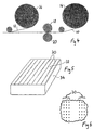
- the paper web 10 forms the outer wall of the bags while the paper web 12 forms the inner wall.
- the web 12 consists of kraft paper only. In this example embodiment it has a porosity such that its air resistance (Gurley) is approximately 5 seconds.
- the weight of the paper is 80gm/m 2 .
- the web 10 which provides the outer wall of the sacks is kraft paper with a weight of 95g/m 2 coated on one surface (which becomes the interior of the outer wall) with 15g/m 2 of polyethylene providing a vapour barrier.
- the two webs are drawn off from supply rollers 14 and 16 and brought together. Before the two webs are brought together the web 10 is passed between a roller 18 bearing an array of needles and a counter roller 20 with a soft surface.
- the needles on roller 18 make bands of perforations in the web 10.
- the two webs are formed in known manner into a continuous flattened tube as shown in Fig.2 in which the overlapping side edge portions of web 12 are glued together at 22 and overlapping side edge portions of web 10 are glued together at 24 so that the tube has an inner wall formed from the web 12 and an outer wall formed form the web 10.
- This tube is cut into lengths and in a subsequent operation each of the cut-off lengths is cut, folded and glued at its ends, so as to form a flattened sack as illustrated by Fig.3.
- the folded over portions of the walls which form the sack bottom are covered over by a strip of paper glued onto them.
- the needle roller 18 which perforates the web 10 has the needles in groups positioned on the roller so as to form bands 30 of perforations which are confined to those portions of the web 10 which become the front and back faces of the finished sack.
- bands 30 of perforations on the front face 32 of the sack, but there are none on the side faces 34.
- the bands on the front face 32 are spaced inwardly from the side edges by about 4cm.
- the bands of perforations are again spaced from the side edges of that face.
- the bands of perforations extend onto the flaps which form the ends of the sack, they are here covered by the glued-on cover strips and by gluing together of the inner and outer walls at the ends.
- each band 30 of perforations contains three lines of perforations, 0.5cm apart, with the perforations in each line spaced 0.6cm apart.
- Each band of perforations therefore contains 5 holes per centimetre along its length.
- the centre lines of the bands of perforations are spaced 3cm apart. This pattern of perforations is illustrated by the detail view at Fig. 6. Of course other patterns of perforations could be used.
- the sack is 31cm wide, 51cm high (i.e length between the top and bottom ends) and 11cm thick when filled.
- the front and back faces each have an area of approximately 1600 cm 2 . Since each band 30 of perforations contains 5 holes per linear centimetre, the total number of holes through each of the front and back faces exceeds 1000 and indeed is in the region of 1500. The density of perforation exceeds 0.8 holes per cm 2 .
- a sheet of vapour barrier material may be laid on a pallet before sacks are stacked onto that pallet.
- a sheet could be a sheet of polyethylene film or, more conveniently, could be a sheet cut from a web 10 but without any perforations.
- a similar sheet can be laid across the sacks at the top of the pallet before securing the entire stack of sacks onto the pallet.
- a number of sacks generally as described above were manufactured. Eight bands 30 of perforations were provided on each of the broad faces, giving an average density of perforation on these faces of approximately 1.2 holes per cm 2 . These sacks were filled with plaster on a high speed filling machine having a plurality of filling nozzles, operating such that an individual sack is filled with 25kg of plaster in a time of approximately 7 seconds. (Even faster times, less than 5 seconds, are possible)
- the plaster is a powder with particle size less than 3000 micrometres, and with a substantial proportion of fine particles with a size less than 250 micrometres.
- the machine was used to fill double wall sacks of the same size, where the vapour barrier was provided as an outer coating on the inner wall, the outer wall was uncoated kraft paper with an air resistance (Gurley) of approximately 16 seconds and the vapour barrier and inner wall were perforated over their side faces and much of their front and back faces with approximately 1.5 holes per cm 2 .
- the vapour barrier was provided as an outer coating on the inner wall
- the outer wall was uncoated kraft paper with an air resistance (Gurley) of approximately 16 seconds and the vapour barrier and inner wall were perforated over their side faces and much of their front and back faces with approximately 1.5 holes per cm 2 .
- the sacks embodying the invention were observed to fill easily, and did not become distended with trapped air. Less plaster dust escaped during filling and the bursting of sacks during filling and subsequent handling was reduced.
- Filled sacks of each kind were stacked horizontally on pallets. Some sacks were laid as single layers on separate pallets, to represent a top layer. At intervals sacks from within the stacks were taken out, and the plaster in them was tested. Sample sacks from the single layers were also tested. The tests on the plaster measured trowelling times and water gauge.
- plaster in sacks embodying this invention and plaster in the comparison sacks underwent a progressive change in properties during a period of 80 days.
- the changes were substantially equal in magnitude with both kinds of sack.
- plaster in sacks from within the stacks i.e. not from the top-layer
- plaster in the sacks embodying the invention showed less change in properties during the storage period than plaster in the comparison sacks.
- the number of perforations through faces of the sack required to give sufficient venting of air during filling can vary from one filling machine to another and can be determined by experimental trials. For example, after trial of the sacks in this example it was found possible to reduce the number of bands of perforations in the back faces of the sacks from eight bands to seven. In further trials with a different filling machine it was found possible to reduce the number of bands of perforation to only four bands on each of the front and back faces.
- the first type of sack was similar to those described in Example 1 with a variation that the web 10, which provides the outer wall of the sacks was kraft paper with a weight of 80 g/m 2 coated on one surface, which again became the interior of the outer wall, with 14 g/m 2 of polyethylene as the vapour barrier.
- the second category of sacks made and tested was the same as the first category except that the perforations through the outer web were confined to only one of the broad faces of the sacks (approximately halving the total number of perforations)
- the third group of sacks which were made and filled were the same as those used as a comparison in the previous example.
Landscapes
- Engineering & Computer Science (AREA)
- Mechanical Engineering (AREA)
- Packages (AREA)
- Bag Frames (AREA)
Description
| Water Gauge (%) - Sacks on Pallet | |||
| Storage time (days) | Comparative | Perforations on both faces | Perforations on one face |
| 5 | 48.1 | 47.7 | 48.6 |
| 21 | 48.1 | 48.4 | 49.2 |
| 34 | 47.7 | 47.8 | 49.0 |
| 47 | 46.9 | 47.4 | 48.7 |
| 61 | 46.9 | 47.1 | 48.9 |
| 83 | 46.0 | 46.6 | 47.3 |
| 110 | 46.2 | 45.9 | 48.5 |
| 138 | 43.6 | 43.1 | 44.4 |
| Trowelling times to final polish (min) - Sacks on Pallets | |||
| Storage time (days) | Comparative | Perforations on both faces | Perforations on one face |
| 5 | 95 | 90 | 85 |
| 21 | 105 | 95 | 90 |
| 34 | 110 | 100 | 100 |
| 47 | 105 | 95 | 95 |
| 61 | 110 | 100 | 100 |
| 83 | 110 | 105 | 100 |
| 110 | 105 | 95 | 90 |
| 138 | 135 | 135 | 120 |
| 185 | - | - | 125 |
| Water Gauge (%) - Bags Stored Separately | |||
| Storage time (days) | Comparative | Perforations on both faces | Perforations on one face |
| 5 | 48.1 | 47.7 | 48.6 |
| 21 | 46.0 | 46.2 | 48.6 |
| 34 | 44.3 | 44.9 | 47.6 |
| 47 | 43.9 | 43.8 | 46.6 |
| 61 | 43.0 | 42.7 | 45.7 |
| 83 | 42.3 | 42.6 | 44.6 |
| Trowelling times to final polish (min) Bags Stored Separately | |||
| Storage time (days) | Comparative | Perforations on both faces | Perforations on one face |
| 5 | 95 | 90 | 85 |
| 21 | 115 | 105 | 105 |
| 34 | 140 | 120 | 110 |
| 47 | 145 | 125 | 110 |
| 61 | 145 | 130 | 110 |
| 83 | 115 | 130 | 115 |
| 110 | - | 125 | 120 |
Claims (14)
- A multi-wall paper sack for a moisture-sensitive powder product, the sack being shaped to provide a pair of opposite broad faces (32) joined by side faces (34) which are narrower than the broad faces (32) and also joined at top and bottom ends, which sack has a paper inner wall (12), which is porous, surrounded by a vapour barrier which is separate from the paper inner wall (12), and a paper outer wall (10), on either or both of the broad faces (32) there being perforations (30) through the vapour barrier with an average density of perforation over the said face (32) exceeding 0.3 holes per cm2, characterised in that the number of perforations (if any) through the vapour barrier at each side face (34) of the sack is sufficiently small that the average density thereof over the side faces (34) is less than 0.1 holes per cm2.
- A sack according to claim 1 wherein the said perforations (30) are provided over one broad face (32) only.
- A sack according to claim 1 or claim 2 wherein the average density of perforation through a broad face (32) exceeds 0.7 holes per cm2.
- A sack according to claim 1, claim 2 or claim 3 wherein the total number of perforations (30) through the vapour barrier on a broad face (32) of the sack exceeds 500.
- A sack according to any one of the preceding claims wherein the vapour barrier is provided as a coating on the inside surface of the paper outer wall (10) and the perforations (30) through the vapour barrier are perforations through the outer paper wall (10) and the vapour barrier.
- A sack according to any one of the preceding claims wherein the total number of perforations through the vapour barrier at each side face (34) is not greater than 50.
- A sack according to any one of the preceding claims wherein the inner layer (12) is sufficiently porous that it has an air resistance (Gurley) of not more than 10 seconds.
- A sack according to any one of the preceding claims wherein the number of perforations (if any) through the inner wall (12) of the sack is sufficiently small that the average density thereof is less than 0.1 holes per cm2.
- A sack according to any one of the preceding claims having a length in the range from 30 to 80 cm, a width in the range from 20 to 70 cm and a thickness in the range from 7 to 20 cm where at least one broad face (32) of the sack has at least 500 perforations (30) through the vapour barrier while on each side face (34) of the sack there are no more than 50 perforations through each wall.
- A sack according to any one of the preceding claims containing a moisture-sensitive powder product.
- Use of a sack as defined in any one of claims 1 to 9 to protect a powder product from moisture.
- Use according to claim 11 wherein the powder product is plaster.
- A method of packaging a powder product, comprising providing a sack according to any one of claims 1 to 9, the sack having a filling aperture, inserting a filling nozzle into the filling aperture of the sack, and filling the sack with the powder product through the filling nozzle.
- A method according to claim 13 in which the sack is filled in 12 seconds or less.
Applications Claiming Priority (3)
| Application Number | Priority Date | Filing Date | Title |
|---|---|---|---|
| GBGB9712819.3A GB9712819D0 (en) | 1997-06-18 | 1997-06-18 | Paper sack |
| GB9712819 | 1997-06-18 | ||
| PCT/GB1998/001766 WO1998057861A1 (en) | 1997-06-18 | 1998-06-17 | Paper sack |
Publications (2)
| Publication Number | Publication Date |
|---|---|
| EP0989943A1 EP0989943A1 (en) | 2000-04-05 |
| EP0989943B1 true EP0989943B1 (en) | 2002-09-18 |
Family
ID=10814491
Family Applications (1)
| Application Number | Title | Priority Date | Filing Date |
|---|---|---|---|
| EP98930874A Expired - Lifetime EP0989943B1 (en) | 1997-06-18 | 1998-06-17 | Paper sack |
Country Status (7)
| Country | Link |
|---|---|
| US (1) | US5988881A (en) |
| EP (1) | EP0989943B1 (en) |
| AU (1) | AU8116298A (en) |
| DE (1) | DE69808085T2 (en) |
| ES (1) | ES2184290T3 (en) |
| GB (1) | GB9712819D0 (en) |
| WO (1) | WO1998057861A1 (en) |
Families Citing this family (18)
| Publication number | Priority date | Publication date | Assignee | Title |
|---|---|---|---|---|
| CA2396362A1 (en) | 2000-01-05 | 2001-07-12 | Saint-Gobain Technical Fabrics Of America, Inc. | Smooth reinforced cementitious boards and methods of making same |
| AT413273B (en) * | 2000-11-21 | 2006-01-15 | Mondi Bags Austria Gmbh | Method of producing paper sack involves forming intermediate layer and paper layer with perforations or breaks |
| WO2002042060A1 (en) * | 2000-11-21 | 2002-05-30 | Frantschach Industrial Packaging Austria Gmbh | Method for producing a paper sack and a paper sack |
| CA2372052C (en) * | 2002-02-12 | 2007-01-09 | Hood Packaging Corporation | Multiwall paper bag |
| US7461234B2 (en) * | 2002-07-01 | 2008-12-02 | Panasonic Corporation | Loosely-biased heterogeneous reconfigurable arrays |
| FR2858302B1 (en) * | 2003-07-30 | 2006-05-26 | Nordson Corp | WATERPROOF AND AIR-PERMEABLE CONTAINER AND METHOD FOR MANUFACTURING THE SAME |
| DE202006020404U1 (en) | 2006-01-26 | 2008-07-31 | Mondi Ag | Multi-ply bag made of paper |
| ATE423868T1 (en) * | 2006-02-08 | 2009-03-15 | Mondi Frantschach Gmbh | WRAPPING PAPER AND PAPER SACK PRODUCED THEREFROM AND METHOD FOR PRODUCING THE WRAPPING PAPER |
| EP1820745A1 (en) | 2006-02-17 | 2007-08-22 | Mondi Packaging AG | Flexible package with vent valve means |
| US20080144979A1 (en) * | 2006-11-06 | 2008-06-19 | Marko I.R.D.C. | Plastic bag with improved air evacuation structure |
| EP2080615A1 (en) * | 2008-01-18 | 2009-07-22 | Dow Global Technologies Inc. | Coated substrates and packages prepared therefrom |
| ATE468276T1 (en) | 2008-03-10 | 2010-06-15 | Billeruds Ab | TWO-LAYER PAPER BAG |
| NZ598695A (en) * | 2011-03-28 | 2012-06-29 | O E & D R Pope Pty Ltd | A recyclable packaging container for dry based powders, grains, particulates and aggregates |
| EP2792609A1 (en) * | 2013-04-18 | 2014-10-22 | Nordfolien GmbH | Packaging container for bulk materials |
| JP5770356B1 (en) * | 2014-12-26 | 2015-08-26 | 株式会社Mib | Deaeration bag for food |
| EP3184694A1 (en) * | 2015-12-21 | 2017-06-28 | BillerudKorsnäs AB | Rainproof paper sack |
| CN107848659A (en) * | 2015-12-22 | 2018-03-27 | 维拉特·萨凡塔利达 | Hybrid construction bag and method for making hybrid construction bag |
| DE102016010858A1 (en) * | 2016-09-07 | 2018-03-08 | Dy-Pack Verpackungen Gustav Dyckerhoff Gmbh | Perforated bag and perforation process |
Family Cites Families (12)
| Publication number | Priority date | Publication date | Assignee | Title |
|---|---|---|---|---|
| US2046146A (en) * | 1935-04-22 | 1936-06-30 | Bemis Bro Bag Co | Bag |
| US2084296A (en) * | 1936-01-20 | 1937-06-15 | Union Bag & Paper Corp | Carbon black sack |
| FR862952A (en) * | 1939-01-23 | 1941-03-20 | Paper bag | |
| US2340546A (en) * | 1939-12-13 | 1944-02-01 | John W Meaker | Container |
| US2593328A (en) * | 1948-07-13 | 1952-04-15 | John W Meaker | Perforated multiple ply bag |
| US3248041A (en) * | 1964-10-21 | 1966-04-26 | Howe Richardson Scale Co | Multiwall bag |
| GB1462941A (en) * | 1974-01-02 | 1977-01-26 | Leer Koninklijke Emballage | Sack |
| DE3202032C2 (en) * | 1982-01-22 | 1985-10-10 | Reuther Verpackung GmbH, 5450 Neuwied | Multi-layer bag open on one side for holding powdery products |
| GB2116144B (en) * | 1982-03-05 | 1985-10-23 | Drg Uk Ltd | Bags or sacks |
| DE8322642U1 (en) * | 1983-08-05 | 1983-10-27 | Niedermayr Papierwarenfabrik Ag, 8200 Rosenheim | Sack with inner film sack |
| NZ209507A (en) * | 1983-10-06 | 1986-07-11 | Canadian Ind | Thermoplastic valve bag:perforated outer wall with mesh inner liner |
| DK166957B2 (en) * | 1992-03-03 | 1996-12-02 | Danapak | FILM FOR MAKING A PACKAGING, PROCEDURE FOR ITS PREPARATION AND APPLICATION OF THE FILM |
-
1997
- 1997-06-18 GB GBGB9712819.3A patent/GB9712819D0/en not_active Ceased
-
1998
- 1998-06-17 US US09/099,484 patent/US5988881A/en not_active Expired - Fee Related
- 1998-06-17 ES ES98930874T patent/ES2184290T3/en not_active Expired - Lifetime
- 1998-06-17 DE DE69808085T patent/DE69808085T2/en not_active Expired - Fee Related
- 1998-06-17 WO PCT/GB1998/001766 patent/WO1998057861A1/en not_active Ceased
- 1998-06-17 EP EP98930874A patent/EP0989943B1/en not_active Expired - Lifetime
- 1998-06-17 AU AU81162/98A patent/AU8116298A/en not_active Abandoned
Also Published As
| Publication number | Publication date |
|---|---|
| AU8116298A (en) | 1999-01-04 |
| WO1998057861A1 (en) | 1998-12-23 |
| DE69808085D1 (en) | 2002-10-24 |
| US5988881A (en) | 1999-11-23 |
| GB9712819D0 (en) | 1997-08-20 |
| ES2184290T3 (en) | 2003-04-01 |
| EP0989943A1 (en) | 2000-04-05 |
| DE69808085T2 (en) | 2003-05-28 |
Similar Documents
| Publication | Publication Date | Title |
|---|---|---|
| US5988881A (en) | Paper sack | |
| FI80651B (en) | PLASTIC PLASTIC SHEET, PLASTIC PLASTIC SHEET WITHOUT PLASTIC MATERIAL AND PLASTIC FOIL FOR SAILING PAOSE. | |
| EP0151489B1 (en) | Package containing quality-retaining agent | |
| US11426035B2 (en) | Film-packaged tissue, manufacturing method for film-packaged tissue, film-packaged tissue set package, and manufacturing method for film-packaged tissue set package | |
| US4270658A (en) | Breathable, sterilizable receptacles for storing articles in sterile condition | |
| US4402402A (en) | Barrier seal multiple-compartment package | |
| US5155973A (en) | Composite wrap and method for wrapping multi-page items | |
| CA2104944A1 (en) | Tubular sachet package | |
| WO1997035711A9 (en) | Thermoplastic bag structure | |
| WO1997035711A1 (en) | Thermoplastic bag structure | |
| PL193981B1 (en) | Soap wrapping | |
| KR100546957B1 (en) | Manufacturing process for individually dosed sheet-like administration forms arranged as a stack in a dispenser and device for inserting a plurality of segregated sheet-like administration forms into a dispenser | |
| EP0559598B1 (en) | Foil for the production of a pack, as well as the method of manufacture and use of such a foil | |
| US4320868A (en) | Envelope material for use in envelope producing machine | |
| US6926655B1 (en) | Method of packaging a web, and a package produced thereby | |
| CA2360653C (en) | Pre-opened resealable bags | |
| US4154390A (en) | Inner pack for multi-block cigarette packs | |
| CA1047451A (en) | Continuous multi-layered packaging assembly | |
| NZ264733A (en) | Bag openable from either end: one end temporarily closed by strip of adhesive tape when bag is filled | |
| US20080063323A1 (en) | Moisture-Repellent Receptacle and Method for the Production Thereof | |
| JPH0211313Y2 (en) | ||
| EP2805896A1 (en) | Reinforced sack | |
| WO2000075028A1 (en) | Filling valve for sacks | |
| JPS591954Y2 (en) | multilayer bag | |
| EP3566857B1 (en) | Bag wall, bag tube and bag produced therefrom and method for producing them |
Legal Events
| Date | Code | Title | Description |
|---|---|---|---|
| PUAI | Public reference made under article 153(3) epc to a published international application that has entered the european phase |
Free format text: ORIGINAL CODE: 0009012 |
|
| 17P | Request for examination filed |
Effective date: 20000107 |
|
| AK | Designated contracting states |
Kind code of ref document: A1 Designated state(s): DE ES FR GB IE |
|
| GRAG | Despatch of communication of intention to grant |
Free format text: ORIGINAL CODE: EPIDOS AGRA |
|
| 17Q | First examination report despatched |
Effective date: 20010523 |
|
| GRAG | Despatch of communication of intention to grant |
Free format text: ORIGINAL CODE: EPIDOS AGRA |
|
| GRAG | Despatch of communication of intention to grant |
Free format text: ORIGINAL CODE: EPIDOS AGRA |
|
| GRAH | Despatch of communication of intention to grant a patent |
Free format text: ORIGINAL CODE: EPIDOS IGRA |
|
| GRAH | Despatch of communication of intention to grant a patent |
Free format text: ORIGINAL CODE: EPIDOS IGRA |
|
| GRAA | (expected) grant |
Free format text: ORIGINAL CODE: 0009210 |
|
| AK | Designated contracting states |
Kind code of ref document: B1 Designated state(s): DE ES FR GB IE |
|
| REG | Reference to a national code |
Ref country code: GB Ref legal event code: FG4D |
|
| REG | Reference to a national code |
Ref country code: IE Ref legal event code: FG4D |
|
| REF | Corresponds to: |
Ref document number: 69808085 Country of ref document: DE Date of ref document: 20021024 |
|
| REG | Reference to a national code |
Ref country code: ES Ref legal event code: FG2A Ref document number: 2184290 Country of ref document: ES Kind code of ref document: T3 |
|
| ET | Fr: translation filed | ||
| PLBE | No opposition filed within time limit |
Free format text: ORIGINAL CODE: 0009261 |
|
| STAA | Information on the status of an ep patent application or granted ep patent |
Free format text: STATUS: NO OPPOSITION FILED WITHIN TIME LIMIT |
|
| 26N | No opposition filed |
Effective date: 20030619 |
|
| PG25 | Lapsed in a contracting state [announced via postgrant information from national office to epo] |
Ref country code: DE Free format text: LAPSE BECAUSE OF NON-PAYMENT OF DUE FEES Effective date: 20040101 |
|
| PGFP | Annual fee paid to national office [announced via postgrant information from national office to epo] |
Ref country code: FR Payment date: 20050608 Year of fee payment: 8 |
|
| PGFP | Annual fee paid to national office [announced via postgrant information from national office to epo] |
Ref country code: IE Payment date: 20050613 Year of fee payment: 8 |
|
| PGFP | Annual fee paid to national office [announced via postgrant information from national office to epo] |
Ref country code: GB Payment date: 20050615 Year of fee payment: 8 |
|
| PGFP | Annual fee paid to national office [announced via postgrant information from national office to epo] |
Ref country code: ES Payment date: 20050728 Year of fee payment: 8 |
|
| PG25 | Lapsed in a contracting state [announced via postgrant information from national office to epo] |
Ref country code: GB Free format text: LAPSE BECAUSE OF NON-PAYMENT OF DUE FEES Effective date: 20060617 |
|
| PG25 | Lapsed in a contracting state [announced via postgrant information from national office to epo] |
Ref country code: IE Free format text: LAPSE BECAUSE OF NON-PAYMENT OF DUE FEES Effective date: 20060619 Ref country code: ES Free format text: LAPSE BECAUSE OF NON-PAYMENT OF DUE FEES Effective date: 20060619 |
|
| GBPC | Gb: european patent ceased through non-payment of renewal fee |
Effective date: 20060617 |
|
| REG | Reference to a national code |
Ref country code: IE Ref legal event code: MM4A |
|
| REG | Reference to a national code |
Ref country code: FR Ref legal event code: ST Effective date: 20070228 |
|
| REG | Reference to a national code |
Ref country code: ES Ref legal event code: FD2A Effective date: 20060619 |
|
| PG25 | Lapsed in a contracting state [announced via postgrant information from national office to epo] |
Ref country code: FR Free format text: LAPSE BECAUSE OF NON-PAYMENT OF DUE FEES Effective date: 20060630 |