EP0989304B1 - Scroll fluid machinery - Google Patents
Scroll fluid machinery Download PDFInfo
- Publication number
- EP0989304B1 EP0989304B1 EP99909294A EP99909294A EP0989304B1 EP 0989304 B1 EP0989304 B1 EP 0989304B1 EP 99909294 A EP99909294 A EP 99909294A EP 99909294 A EP99909294 A EP 99909294A EP 0989304 B1 EP0989304 B1 EP 0989304B1
- Authority
- EP
- European Patent Office
- Prior art keywords
- spiral body
- refrigerant
- winding
- fluid machine
- compression chamber
- Prior art date
- Legal status (The legal status is an assumption and is not a legal conclusion. Google has not performed a legal analysis and makes no representation as to the accuracy of the status listed.)
- Expired - Lifetime
Links
- 239000012530 fluid Substances 0.000 title claims description 24
- 230000006835 compression Effects 0.000 claims description 48
- 238000007906 compression Methods 0.000 claims description 48
- 238000004804 winding Methods 0.000 claims description 46
- 239000003507 refrigerant Substances 0.000 claims description 37
- 230000007423 decrease Effects 0.000 claims description 4
- 238000007599 discharging Methods 0.000 claims description 3
- 230000003247 decreasing effect Effects 0.000 description 3
- 230000003111 delayed effect Effects 0.000 description 1
- 238000010438 heat treatment Methods 0.000 description 1
Images

Classifications
-
- F—MECHANICAL ENGINEERING; LIGHTING; HEATING; WEAPONS; BLASTING
- F04—POSITIVE - DISPLACEMENT MACHINES FOR LIQUIDS; PUMPS FOR LIQUIDS OR ELASTIC FLUIDS
- F04C—ROTARY-PISTON, OR OSCILLATING-PISTON, POSITIVE-DISPLACEMENT MACHINES FOR LIQUIDS; ROTARY-PISTON, OR OSCILLATING-PISTON, POSITIVE-DISPLACEMENT PUMPS
- F04C18/00—Rotary-piston pumps specially adapted for elastic fluids
- F04C18/02—Rotary-piston pumps specially adapted for elastic fluids of arcuate-engagement type, i.e. with circular translatory movement of co-operating members, each member having the same number of teeth or tooth-equivalents
-
- F—MECHANICAL ENGINEERING; LIGHTING; HEATING; WEAPONS; BLASTING
- F04—POSITIVE - DISPLACEMENT MACHINES FOR LIQUIDS; PUMPS FOR LIQUIDS OR ELASTIC FLUIDS
- F04C—ROTARY-PISTON, OR OSCILLATING-PISTON, POSITIVE-DISPLACEMENT MACHINES FOR LIQUIDS; ROTARY-PISTON, OR OSCILLATING-PISTON, POSITIVE-DISPLACEMENT PUMPS
- F04C18/00—Rotary-piston pumps specially adapted for elastic fluids
- F04C18/02—Rotary-piston pumps specially adapted for elastic fluids of arcuate-engagement type, i.e. with circular translatory movement of co-operating members, each member having the same number of teeth or tooth-equivalents
- F04C18/0207—Rotary-piston pumps specially adapted for elastic fluids of arcuate-engagement type, i.e. with circular translatory movement of co-operating members, each member having the same number of teeth or tooth-equivalents both members having co-operating elements in spiral form
- F04C18/0246—Details concerning the involute wraps or their base, e.g. geometry
- F04C18/0269—Details concerning the involute wraps
Definitions
- the present invention relates to a scroll fluid machine such as a scroll compressor and a scroll expansion device.
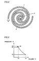
- Fig. 2 illustrates first and second spiral bodies 1 and 2 in a scroll fluid machine disclosed in Japanese Patent Laying-Open No. 60-252102.
- the first spiral body 1 corresponds to a fixed scroll and the second spiral body 2 corresponds to a movable scroll.
- a discharge port 3 is provided in the vicinity of winding starting ends of the first and second spiral bodies 1 and 2 in order to discharge compressed refrigerant.
- a thickness t4 of the first spiral body 1 located in the vicinity of discharge port 3 is defined to be larger than a thickness t5 of a winding finishing end of the first spiral body 1.
- the second spiral body 2 is similarly shaped.
- the increased thickness t4 of the winding starting ends of the first and second spiral bodies 1 and 2 in the vicinity of discharge port 3 can enhance the strength of the portion near the winding starting ends of the first and second spiral bodies 1 and 2, and prevent leakage of refrigerant occurring at the central portion.
- Fig. 3 shows a relation between pressure and volume in a compression chamber formed by the first and second spiral bodies 1 and 2, where P1 and P1' represent the pressure in the compression chamber when refrigerant is discharged, P2 represents the pressure in the compression chamber when the refrigerant is taken in, V1 represents the volume of the compression chamber when the refrigerant is taken in, and V2 represents the volume of the compression chamber when the refrigerant is discharged.
- An object of the invention is to prevent occurrence of the phenomenon of excessive compression in a scroll fluid machine having a pair of spiral bodies where the thickness thereof increases in a direction from winding finishing ends toward winding starting ends.
- a scroll fluid machine includes first and second spiral bodies having the thickness increasing in a direction from winding finishing ends toward winding starting ends, first and second compression chambers formed between the first and second spiral bodies and located an the innermost side the first compression chamber being formed by an inner surface of the first spiral body and an outer surface of the second spiral body and a discharge port discharging compressed refrigerant successively from the first and second compression chambers.
- the scroll fluid machine is provided with a refrigerant discharge timing advancing means for advancing the timing at which refrigerant is discharged from the first compression chamber relative to the refrigerant discharge timing of the second compression chamber.
- the refrigerant discharge timing advancing means thus provided allows the timing at which refrigerant is discharged from the first compression chamber to precede the refrigerant discharge timing of the second compression chamber. Discharge resistance of the refrigerant is accordingly reduced compared with the conventional machine to prevent the excessive compression from happening.
- the first spiral body has an extension which prolongs the winding finishing end of the first spiral body to a region near the winding finishing end of the second spiral body, and the discharge port has an opening advancing portion for opening the first compression chamber earlier.
- the refrigerant discharge timing advancing means includes the extension and the opening advancing portion.
- the extension thus provided to the first spiral body enables the pressure in the first compression chamber to rise to a desired pressure earlier than the second compression chamber, for example.
- the first compression chamber where the pressure attains the desired pressure can be opened relatively earlier to discharge the refrigerant, since the discharge port has the opening advancing portion. Accordingly, the timing at which the refrigerant is discharged from the first compression chamber can be made earlier than the refrigerant discharge timing of the second compression chamber, so that the discharge resistance of the refrigerant can be decreased.
- the opening advancing portion is preferably formed by expanding the discharge port toward the first compression chamber.
- the thickness of the winding finishing end of the first spiral body is preferably smaller than that of the winding finishing end of the second spiral body.
- the thickness of the extension gradually decreases toward the winding finishing end of the first spiral body.
- the scroll fluid machine according to the invention is preferably provided with one intake port for taking in the refrigerant.
- the scroll fluid machine includes a movable scroll and a fixed scroll, the first spiral body is provided at the fixed scroll, and the second spiral body is provided at the movable scroll.
- the thickness of the second spiral body in the vicinity of its winding starting end is preferably larger than that of the first spiral body in the vicinity of its winding starting end, and the opening advancing portion preferably has a shape which allows the opening advancing portion to be closed temporarily by a part near the winding starting end of the second spiral body.
- an opening advancing portion (3a) is temporarily closed by a part near a winding starting end (2a) of a second spiral body (2) immediately before the refrigerant is discharged from a first compression chamber (4).
- Fig. 1 is a plan view illustrating first and second spiral bodies according to the one embodiment of the invention.
- a scroll fluid machine includes a fixed scroll having the first spiral body 1, and a movable scroll having the second spiral body 2.
- the first spiral body 1 includes a winding starting end 1a, a winding finishing end 1b, and an extension 1c.
- a thickness t1 of winding starting end 1a is defined to be greater than a thickness t2 of winding finishing end 1b.
- the shape of the first spiral body 1 is selected such that the thickness of the spiral body gradually increases in a direction from winding finishing end 1b toward winding starting end 1a.
- Extension 1c is generated by extending winding finishing end 1b by approximately 180° as shown in Fig. 1. Such extension 1c enables pressure in the first compression chamber 4 to rise to a desired pressure earlier than the second compression chamber 5.
- the second spiral body 2 also includes a winding starting end 2a and a winding finishing end 2b, and the thickness thereof increases in a direction from winding finishing end 2b toward winding starting end 2a.
- Winding finishing end 2b is located in the vicinity of winding finishing end 1b, and the thickness t2 of winding finishing end 1b is smaller than a thickness t3 of winding finishing end 2b. The reason is that the first spiral body 1 has extension 1c and the thickness thereof gradually decreases toward winding finishing end 1b even at extension 1c.
- Discharge port 3 includes an opening advancing portion 3a for opening the first compression chamber 4 earlier.
- a boundary between discharge port 3 and opening advancing portion 3a is indicated by an imaginary line in Fig. 1 for convenience of description.
- the first compression chamber 4 is formed by an inner surface of the first spiral body 1 and an outer surface of the second spiral body 2, and the pressure therein increases to attain a desired pressure earlier than the second compression chamber 5 since the first spiral body 1 has extension 1c. Because opening advancing portion 3a is provided at discharge port 3, the first compression chamber 4 which has attained the desired pressure earlier than the second compression chamber 5 can be opened earlier. Accordingly, the timing at which the refrigerant is discharged from the second compression chamber 5 is delayed relative to the refrigerant discharge timing of the first compression chamber 4 , and the discharge resistance of the refrigerant can thus be decreased. As a result, occurrence of the excessive compression state can effectively be avoided to reduce loss of the scroll fluid machine.
- extension 1c and opening advancing portion 3a are provided as refrigerant discharge timing advancing means for advancing the timing at which refrigerant is discharged from the first compression chamber 4, another scheme may be employed for advancing the refrigerant discharge timing of the first compression chamber 4.
- Discharge port 3 can be produced with a sufficient margin in the central portion of the first spiral body 1 since the thickness of extension 1c can be made smaller than the thickness t3 of the winding finishing end 2b. Accordingly, the opening area of discharge port 3 can be increased to further decrease discharge resistance.
- extension 1c thus provided enables intake ports (not shown) for taking in the refrigerant to be integrated into one location, and the loss in inlet pressure and excessive inlet heating can be decreased.
- the present invention is advantageously applicable to a scroll fluid machine.
Landscapes
- Engineering & Computer Science (AREA)
- Mechanical Engineering (AREA)
- General Engineering & Computer Science (AREA)
- Rotary Pumps (AREA)
Description
- The present invention relates to a scroll fluid machine such as a scroll compressor and a scroll expansion device.
- Fig. 2 illustrates first and second
spiral bodies spiral body 1 corresponds to a fixed scroll and the secondspiral body 2 corresponds to a movable scroll. - As shown in Fig. 2, a
discharge port 3 is provided in the vicinity of winding starting ends of the first and secondspiral bodies spiral body 1 located in the vicinity ofdischarge port 3 is defined to be larger than a thickness t5 of a winding finishing end of the firstspiral body 1. The secondspiral body 2 is similarly shaped. - The increased thickness t4 of the winding starting ends of the first and second
spiral bodies discharge port 3 can enhance the strength of the portion near the winding starting ends of the first and secondspiral bodies - However, the increased thickness at the central portion of the spiral bodies causes a problem described below. Using Fig. 3, the problem is described. Fig. 3 shows a relation between pressure and volume in a compression chamber formed by the first and second
spiral bodies - Since the thickness t4 of the winding starting ends of the first and second
spiral bodies discharge port 3 is small unless the first and secondspiral bodies discharge port 3 accordingly increases to excessively raise the pressure in the compression chamber fromP 1 to P 1', for example, as shown in Fig. 3 when the refrigerant is discharged, which is referred to as phenomenon of excessive compression. As a result, an extra work W becomes necessary, leading to increase in loss.
Further scroll fluid machines are known from JP 08021381 and EP 0446635 A2. - The present invention is made to solve such a problem as described above. An object of the invention is to prevent occurrence of the phenomenon of excessive compression in a scroll fluid machine having a pair of spiral bodies where the thickness thereof increases in a direction from winding finishing ends toward winding starting ends.
- According to the invention, a scroll fluid machine includes first and second spiral bodies having the thickness increasing in a direction from winding finishing ends toward winding starting ends, first and second compression chambers formed between the first and second spiral bodies and located an the innermost side the first compression chamber being formed by an inner surface of the first spiral body and an outer surface of the second spiral body and a discharge port discharging compressed refrigerant successively from the first and second compression chambers. The scroll fluid machine is provided with a refrigerant discharge timing advancing means for advancing the timing at which refrigerant is discharged from the first compression chamber relative to the refrigerant discharge timing of the second compression chamber.
- The refrigerant discharge timing advancing means thus provided allows the timing at which refrigerant is discharged from the first compression chamber to precede the refrigerant discharge timing of the second compression chamber. Discharge resistance of the refrigerant is accordingly reduced compared with the conventional machine to prevent the excessive compression from happening.
- In the scroll fluid machine according to the invention, the first spiral body has an extension which prolongs the winding finishing end of the first spiral body to a region near the winding finishing end of the second spiral body, and the discharge port has an opening advancing portion for opening the first compression chamber earlier. The refrigerant discharge timing advancing means includes the extension and the opening advancing portion.
- The extension thus provided to the first spiral body enables the pressure in the first compression chamber to rise to a desired pressure earlier than the second compression chamber, for example. The first compression chamber where the pressure attains the desired pressure can be opened relatively earlier to discharge the refrigerant, since the discharge port has the opening advancing portion. Accordingly, the timing at which the refrigerant is discharged from the first compression chamber can be made earlier than the refrigerant discharge timing of the second compression chamber, so that the discharge resistance of the refrigerant can be decreased.
- The opening advancing portion is preferably formed by expanding the discharge port toward the first compression chamber.
- The thickness of the winding finishing end of the first spiral body is preferably smaller than that of the winding finishing end of the second spiral body.
- Preferably, the thickness of the extension gradually decreases toward the winding finishing end of the first spiral body.
- The scroll fluid machine according to the invention is preferably provided with one intake port for taking in the refrigerant.
- Further, the scroll fluid machine according to the invention includes a movable scroll and a fixed scroll, the first spiral body is provided at the fixed scroll, and the second spiral body is provided at the movable scroll.
- The thickness of the second spiral body in the vicinity of its winding starting end is preferably larger than that of the first spiral body in the vicinity of its winding starting end, and the opening advancing portion preferably has a shape which allows the opening advancing portion to be closed temporarily by a part near the winding starting end of the second spiral body. Referring to Fig. 1, for example, an opening advancing portion (3a) is temporarily closed by a part near a winding starting end (2a) of a second spiral body (2) immediately before the refrigerant is discharged from a first compression chamber (4).
-
- Fig. 1 is a plan view illustrating first and second spiral bodies of a scroll fluid machine according to one embodiment of the invention.
- Fig. 2 is a plan view illustrating first and second spiral bodies in a conventional scroll fluid machine.
- Fig. 3 illustrates a relation between pressure and volume in a compression chamber.
- One embodiment of the invention is hereinafter described using Fig. 1. Fig. 1 is a plan view illustrating first and second spiral bodies according to the one embodiment of the invention.
- Referring to Fig. 1, a scroll fluid machine according to the invention includes a fixed scroll having the first
spiral body 1, and a movable scroll having the secondspiral body 2. A plurality of compression chambers, represented by first andsecond compression chambers spiral bodies - The first
spiral body 1 includes awinding starting end 1a, awinding finishing end 1b, and anextension 1c. A thickness t1 of winding startingend 1a is defined to be greater than a thickness t2 of winding finishingend 1b. Specifically, the shape of the firstspiral body 1 is selected such that the thickness of the spiral body gradually increases in a direction from windingfinishing end 1b toward winding startingend 1a.Extension 1c is generated by extending windingfinishing end 1b by approximately 180° as shown in Fig. 1.Such extension 1c enables pressure in thefirst compression chamber 4 to rise to a desired pressure earlier than thesecond compression chamber 5. - The second
spiral body 2 also includes awinding starting end 2a and awinding finishing end 2b, and the thickness thereof increases in a direction from winding finishingend 2b toward winding startingend 2a. Winding finishingend 2b is located in the vicinity of winding finishingend 1b, and the thickness t2 of windingfinishing end 1b is smaller than a thickness t3 of winding finishingend 2b. The reason is that the firstspiral body 1 hasextension 1c and the thickness thereof gradually decreases toward windingfinishing end 1b even atextension 1c. - The fixed scroll located in the vicinity of winding starting
ends discharge port 3 for discharging compressed refrigerant.Discharge port 3 includes an opening advancingportion 3a for opening thefirst compression chamber 4 earlier. A boundary betweendischarge port 3 and opening advancingportion 3a is indicated by an imaginary line in Fig. 1 for convenience of description. - The
first compression chamber 4 is formed by an inner surface of the firstspiral body 1 and an outer surface of the secondspiral body 2, and the pressure therein increases to attain a desired pressure earlier than thesecond compression chamber 5 since the firstspiral body 1 hasextension 1c. Because opening advancingportion 3a is provided atdischarge port 3, thefirst compression chamber 4 which has attained the desired pressure earlier than thesecond compression chamber 5 can be opened earlier. Accordingly, the timing at which the refrigerant is discharged from thesecond compression chamber 5 is delayed relative to the refrigerant discharge timing of thefirst compression chamber 4 , and the discharge resistance of the refrigerant can thus be decreased. As a result, occurrence of the excessive compression state can effectively be avoided to reduce loss of the scroll fluid machine. - Although description of the embodiment above is presented for the case in which
extension 1c and opening advancingportion 3a are provided as refrigerant discharge timing advancing means for advancing the timing at which refrigerant is discharged from thefirst compression chamber 4, another scheme may be employed for advancing the refrigerant discharge timing of thefirst compression chamber 4. -
Discharge port 3 can be produced with a sufficient margin in the central portion of the firstspiral body 1 since the thickness ofextension 1c can be made smaller than the thickness t3 of thewinding finishing end 2b. Accordingly, the opening area ofdischarge port 3 can be increased to further decrease discharge resistance. - In addition,
extension 1c thus provided enables intake ports (not shown) for taking in the refrigerant to be integrated into one location, and the loss in inlet pressure and excessive inlet heating can be decreased. - Using the scroll fluid machine according to the invention, occurrence of the state of excessive compression can advantageously be avoided to reduce the loss due to the excessive compression.
- The present invention is advantageously applicable to a scroll fluid machine.
Claims (7)
- A scroll fluid machine including first and second spiral bodies (1, 2) having a thickness increasing in a direction from winding finishing ends (1b, 2b) toward winding starting ends (1a, 2a), first and second compression chambers (4, 5) formed between the first and second spiral bodies (1, 2) to be located on the innermost side, and a discharge port (3) for discharging compressed refrigerant successively from the first and second compression chambers (4, 5), wherein
the first compression chamber is formed by an inner surface of the first spiral body and an outer surface of the second spiral body, said scroll fluid machine includes refrigerant discharge timing
advancing means for advancing a timing at which refrigerant is discharged from said first compression chamber (4) relative to a timing at which refrigerant is discharged from said second compression chamber (5);
and wherein said first spiral body (1) includes an extension (1c) extending the winding finishing end (1b) substantially at the same level to the winding finishing end (2b) of said second spiral body (2),
characterized in that said discharge port (3) includes an opening advancing portion (3a)
for opening said first compression chamber (4) earlier, and
said refrigerant discharge timing advancing means includes said extension (1c) and said opening advancing portion (3a). - The scroll fluid machine according to claim 1, wherein
said opening advancing portion (3 a) is formed by expanding said discharge port (3) toward said first compression chamber (4). - The scroll fluid machine according to claim 1, wherein
a thickness (t2) of the winding finishing end (1b) of said first spiral body (1) is smaller than a thickness (t3) of the winding finishing end (2b) of said second spiral body (2). - The scroll fluid machine according to claim 1, wherein a thickness of said extension (1c) gradually decreases toward the winding finishing end (1b) of said first spiral body (1).
- The scroll fluid machine according to claim 1, including one intake port for taking in refrigerant.
- The scroll fluid machine according to claim 1, including a movable scroll and a fixed scroll, wherein
said first spiral body (1) is provided at said fixed scroll, and
said second spiral body (2) is provided at said movable scroll. - The scroll fluid machine according to claim 6, wherein
the thickness of said second spiral body (2) in the vicinity of its winding starting end (2a) is larger than the thickness of said first spiral body (1) in the vicinity of its winding starting end (1a), and
said opening advancing portion (3a) has a shape which allows said opening advancing portion (3a) to be closed temporarily by said second spiral body (2) in the vicinity of the winding starting end (2a).
Applications Claiming Priority (3)
| Application Number | Priority Date | Filing Date | Title |
|---|---|---|---|
| JP9603698 | 1998-04-08 | ||
| JP9603698 | 1998-04-08 | ||
| PCT/JP1999/001435 WO1999053202A1 (en) | 1998-04-08 | 1999-03-19 | Scroll fluid machinery |
Publications (3)
| Publication Number | Publication Date |
|---|---|
| EP0989304A1 EP0989304A1 (en) | 2000-03-29 |
| EP0989304A4 EP0989304A4 (en) | 2000-08-23 |
| EP0989304B1 true EP0989304B1 (en) | 2006-03-15 |
Family
ID=14154257
Family Applications (1)
| Application Number | Title | Priority Date | Filing Date |
|---|---|---|---|
| EP99909294A Expired - Lifetime EP0989304B1 (en) | 1998-04-08 | 1999-03-19 | Scroll fluid machinery |
Country Status (11)
| Country | Link |
|---|---|
| US (1) | US6217301B1 (en) |
| EP (1) | EP0989304B1 (en) |
| JP (2) | JP3940822B2 (en) |
| KR (1) | KR100462088B1 (en) |
| CN (1) | CN1128295C (en) |
| CA (1) | CA2287444A1 (en) |
| DE (1) | DE69930372T2 (en) |
| ES (1) | ES2260902T3 (en) |
| MY (1) | MY116023A (en) |
| TW (1) | TW394811B (en) |
| WO (1) | WO1999053202A1 (en) |
Families Citing this family (7)
| Publication number | Priority date | Publication date | Assignee | Title |
|---|---|---|---|---|
| JP2006257941A (en) * | 2005-03-16 | 2006-09-28 | Sanden Corp | Scroll compressor |
| US8425211B2 (en) * | 2007-08-22 | 2013-04-23 | Spinnler Engineering | Positive displacement machine according to the spiral principle |
| JP5500566B2 (en) * | 2008-04-10 | 2014-05-21 | サンデン株式会社 | Scroll type fluid machinery |
| KR101811291B1 (en) | 2011-04-28 | 2017-12-26 | 엘지전자 주식회사 | Scroll compressor |
| KR101216466B1 (en) | 2011-10-05 | 2012-12-31 | 엘지전자 주식회사 | Scroll compressor with oldham ring |
| KR101277213B1 (en) | 2011-10-11 | 2013-06-24 | 엘지전자 주식회사 | Scroll compressor with bypass hole |
| KR101275190B1 (en) | 2011-10-12 | 2013-06-18 | 엘지전자 주식회사 | Scroll compressor |
Family Cites Families (25)
| Publication number | Priority date | Publication date | Assignee | Title |
|---|---|---|---|---|
| JPS5620701A (en) | 1979-07-27 | 1981-02-26 | Hitachi Ltd | Scroll fluid machine |
| JPS58135393A (en) * | 1982-02-08 | 1983-08-11 | Hitachi Ltd | Motor driven compressor |
| JPS5958187A (en) * | 1982-09-26 | 1984-04-03 | Sanden Corp | Scroll type compressor |
| JPS60252102A (en) | 1984-05-30 | 1985-12-12 | Hitachi Ltd | Scroll fluid machine |
| JPS61175293A (en) * | 1985-01-30 | 1986-08-06 | Matsushita Electric Ind Co Ltd | scroll compressor |
| US4781549A (en) * | 1985-09-30 | 1988-11-01 | Copeland Corporation | Modified wrap scroll-type machine |
| JPS63138186A (en) * | 1986-11-28 | 1988-06-10 | Mitsui Seiki Kogyo Co Ltd | Scroll compressor |
| US4886434A (en) * | 1987-02-20 | 1989-12-12 | Sanyo Electric Co., Ltd. | Scroll compressor having discharge part communicating with two compression spaces simultaneously |
| JPS63205481A (en) * | 1987-02-20 | 1988-08-24 | Sanyo Electric Co Ltd | Scroll compressor |
| JPS63255585A (en) * | 1987-04-10 | 1988-10-21 | Sanyo Electric Co Ltd | Scroll compressor |
| JPS63215892A (en) * | 1987-03-02 | 1988-09-08 | Sanyo Electric Co Ltd | Scroll compressor |
| JPS6463686A (en) * | 1987-09-04 | 1989-03-09 | Hitachi Ltd | Scroll compressor |
| JP2595064B2 (en) * | 1988-09-19 | 1997-03-26 | 株式会社日立製作所 | Scroll fluid machine |
| JPH02264178A (en) * | 1988-12-13 | 1990-10-26 | Mitsubishi Electric Corp | Scroll fluid machine |
| US5056336A (en) * | 1989-03-06 | 1991-10-15 | American Standard Inc. | Scroll apparatus with modified scroll profile |
| JPH0772543B2 (en) * | 1989-08-31 | 1995-08-02 | ダイキン工業株式会社 | Scroll compressor |
| US5022834A (en) * | 1990-01-16 | 1991-06-11 | Carrier Corporation | Scroll compressor with enhanced discharge port |
| DE69132650T2 (en) * | 1990-02-13 | 2002-05-08 | Anest Iwata Corp., Tokio/Tokyo | Spiral displacement machine |
| JP2892799B2 (en) * | 1990-09-13 | 1999-05-17 | 株式会社豊田自動織機製作所 | Scroll compressor |
| JPH051882U (en) * | 1991-06-27 | 1993-01-14 | 株式会社豊田自動織機製作所 | Scroll compressor |
| JP3106721B2 (en) | 1991-09-19 | 2000-11-06 | ダイキン工業株式会社 | Scroll compressor |
| JP3036271B2 (en) * | 1992-12-03 | 2000-04-24 | 株式会社豊田自動織機製作所 | Scroll compressor |
| JPH07119654A (en) | 1993-10-20 | 1995-05-09 | Sanden Corp | Scroll type compressor |
| JP3543367B2 (en) * | 1994-07-01 | 2004-07-14 | ダイキン工業株式会社 | Scroll compressor |
| JPH09195959A (en) * | 1996-01-11 | 1997-07-29 | Toshiba Corp | Scroll compressor |
-
1999
- 1999-03-19 CA CA002287444A patent/CA2287444A1/en not_active Abandoned
- 1999-03-19 EP EP99909294A patent/EP0989304B1/en not_active Expired - Lifetime
- 1999-03-19 WO PCT/JP1999/001435 patent/WO1999053202A1/en not_active Ceased
- 1999-03-19 US US09/403,126 patent/US6217301B1/en not_active Expired - Lifetime
- 1999-03-19 DE DE69930372T patent/DE69930372T2/en not_active Expired - Lifetime
- 1999-03-19 CN CN99800460A patent/CN1128295C/en not_active Expired - Lifetime
- 1999-03-19 ES ES99909294T patent/ES2260902T3/en not_active Expired - Lifetime
- 1999-03-19 KR KR10-1999-7011114A patent/KR100462088B1/en not_active Expired - Lifetime
- 1999-03-19 JP JP55146699A patent/JP3940822B2/en not_active Expired - Lifetime
- 1999-03-25 TW TW088104739A patent/TW394811B/en not_active IP Right Cessation
- 1999-03-26 MY MYPI99001173A patent/MY116023A/en unknown
-
2007
- 2007-01-25 JP JP2007015235A patent/JP2007100713A/en active Pending
Also Published As
| Publication number | Publication date |
|---|---|
| JP3940822B2 (en) | 2007-07-04 |
| US6217301B1 (en) | 2001-04-17 |
| WO1999053202A1 (en) | 1999-10-21 |
| JP2007100713A (en) | 2007-04-19 |
| CA2287444A1 (en) | 1999-10-21 |
| CN1128295C (en) | 2003-11-19 |
| EP0989304A4 (en) | 2000-08-23 |
| DE69930372D1 (en) | 2006-05-11 |
| EP0989304A1 (en) | 2000-03-29 |
| CN1263585A (en) | 2000-08-16 |
| TW394811B (en) | 2000-06-21 |
| ES2260902T3 (en) | 2006-11-01 |
| MY116023A (en) | 2003-10-31 |
| DE69930372T2 (en) | 2006-12-07 |
| KR20010013133A (en) | 2001-02-26 |
| KR100462088B1 (en) | 2004-12-17 |
Similar Documents
| Publication | Publication Date | Title |
|---|---|---|
| KR100294175B1 (en) | Scroll compressor with reduced separating force between fixed and orbiting scroll members | |
| US6413058B1 (en) | Variable capacity modulation for scroll compressor | |
| US5853288A (en) | Scroll compressor having a counterboring part communicating with an intermediate pressure chamber | |
| EP0997645A1 (en) | Scroll type fluid machine | |
| JP2007100713A (en) | Scroll fluid machinery | |
| KR20000017312A (en) | Unequal injection ports for scroll compressors | |
| EP0318189B1 (en) | Scroll machine | |
| KR0183505B1 (en) | Scroll Fluid Machine | |
| US6364643B1 (en) | Scroll compressor with dual suction passages which merge into suction path | |
| EP1262665B1 (en) | Scroll compressor | |
| JPS61132782A (en) | Manufacture of compressor valve cover | |
| KR20180126367A (en) | Scroll compressor for a vehicle air-conditioning system | |
| JPWO1999053202A1 (en) | Scroll fluid machinery | |
| EP1024288B1 (en) | Variable flank relief for scroll wraps | |
| US6113372A (en) | Scroll compressor with discharge chamber groove | |
| JP4403739B2 (en) | Screw compressor | |
| US4927341A (en) | Scroll machine with relieved flank surface | |
| JP3932659B2 (en) | Refrigerant suction structure in compressor | |
| JPS63272988A (en) | Two stage compression type compressor | |
| JPH0392592A (en) | Scroll type compressor | |
| US6969243B1 (en) | Scroll compressor with recess on crankcase or orbiting scroll | |
| JP3018060B2 (en) | Gas compressor manufacturing method and gas compressor | |
| KR100234765B1 (en) | Axial sealing structure for scroll compressor | |
| JP2005535827A (en) | Helical screw rotor compressor | |
| KR0162477B1 (en) | Discharge Structure of Scroll Compressor |
Legal Events
| Date | Code | Title | Description |
|---|---|---|---|
| PUAI | Public reference made under article 153(3) epc to a published international application that has entered the european phase |
Free format text: ORIGINAL CODE: 0009012 |
|
| 17P | Request for examination filed |
Effective date: 19991020 |
|
| AK | Designated contracting states |
Kind code of ref document: A1 Designated state(s): BE DE ES FR GB IT |
|
| A4 | Supplementary search report drawn up and despatched |
Effective date: 20000712 |
|
| AK | Designated contracting states |
Kind code of ref document: A4 Designated state(s): BE DE ES FR GB IT |
|
| RIN1 | Information on inventor provided before grant (corrected) |
Inventor name: KAJIWARA, MIKIO Inventor name: UEDA, SHUSAKU Inventor name: YOSHII, TOSHIAKI Inventor name: YOSHIMURA,KEIJI Inventor name: KUROIWA, HIROYUKI |
|
| 17Q | First examination report despatched |
Effective date: 20040607 |
|
| GRAP | Despatch of communication of intention to grant a patent |
Free format text: ORIGINAL CODE: EPIDOSNIGR1 |
|
| GRAS | Grant fee paid |
Free format text: ORIGINAL CODE: EPIDOSNIGR3 |
|
| GRAA | (expected) grant |
Free format text: ORIGINAL CODE: 0009210 |
|
| RIN1 | Information on inventor provided before grant (corrected) |
Inventor name: KAJIWARA, MIKIO Inventor name: UEDA, SHUSAKU Inventor name: YOSHII, TOSHIAKI Inventor name: YOSHIMURA,KEIJI Inventor name: KUROIWA, HIROYUKI |
|
| AK | Designated contracting states |
Kind code of ref document: B1 Designated state(s): BE DE ES FR GB IT |
|
| REG | Reference to a national code |
Ref country code: GB Ref legal event code: FG4D |
|
| REF | Corresponds to: |
Ref document number: 69930372 Country of ref document: DE Date of ref document: 20060511 Kind code of ref document: P |
|
| ET | Fr: translation filed | ||
| REG | Reference to a national code |
Ref country code: ES Ref legal event code: FG2A Ref document number: 2260902 Country of ref document: ES Kind code of ref document: T3 |
|
| PLBE | No opposition filed within time limit |
Free format text: ORIGINAL CODE: 0009261 |
|
| STAA | Information on the status of an ep patent application or granted ep patent |
Free format text: STATUS: NO OPPOSITION FILED WITHIN TIME LIMIT |
|
| 26N | No opposition filed |
Effective date: 20061218 |
|
| REG | Reference to a national code |
Ref country code: FR Ref legal event code: PLFP Year of fee payment: 17 |
|
| REG | Reference to a national code |
Ref country code: FR Ref legal event code: PLFP Year of fee payment: 18 |
|
| REG | Reference to a national code |
Ref country code: FR Ref legal event code: PLFP Year of fee payment: 19 |
|
| REG | Reference to a national code |
Ref country code: FR Ref legal event code: PLFP Year of fee payment: 20 |
|
| PGFP | Annual fee paid to national office [announced via postgrant information from national office to epo] |
Ref country code: DE Payment date: 20180306 Year of fee payment: 20 Ref country code: GB Payment date: 20180314 Year of fee payment: 20 |
|
| PGFP | Annual fee paid to national office [announced via postgrant information from national office to epo] |
Ref country code: FR Payment date: 20180223 Year of fee payment: 20 Ref country code: IT Payment date: 20180321 Year of fee payment: 20 Ref country code: BE Payment date: 20180214 Year of fee payment: 20 |
|
| PGFP | Annual fee paid to national office [announced via postgrant information from national office to epo] |
Ref country code: ES Payment date: 20180404 Year of fee payment: 20 |
|
| REG | Reference to a national code |
Ref country code: DE Ref legal event code: R071 Ref document number: 69930372 Country of ref document: DE |
|
| REG | Reference to a national code |
Ref country code: GB Ref legal event code: PE20 Expiry date: 20190318 |
|
| PG25 | Lapsed in a contracting state [announced via postgrant information from national office to epo] |
Ref country code: GB Free format text: LAPSE BECAUSE OF EXPIRATION OF PROTECTION Effective date: 20190318 |
|
| REG | Reference to a national code |
Ref country code: BE Ref legal event code: MK Effective date: 20190319 |
|
| REG | Reference to a national code |
Ref country code: ES Ref legal event code: FD2A Effective date: 20201204 |
|
| PG25 | Lapsed in a contracting state [announced via postgrant information from national office to epo] |
Ref country code: ES Free format text: LAPSE BECAUSE OF EXPIRATION OF PROTECTION Effective date: 20190320 |