EP0988990B1 - Ink-jet printer nozzle defect detection method and device - Google Patents
Ink-jet printer nozzle defect detection method and device Download PDFInfo
- Publication number
- EP0988990B1 EP0988990B1 EP99307507A EP99307507A EP0988990B1 EP 0988990 B1 EP0988990 B1 EP 0988990B1 EP 99307507 A EP99307507 A EP 99307507A EP 99307507 A EP99307507 A EP 99307507A EP 0988990 B1 EP0988990 B1 EP 0988990B1
- Authority
- EP
- European Patent Office
- Prior art keywords
- ink
- group
- test pattern
- light receiving
- ink drops
- Prior art date
- Legal status (The legal status is an assumption and is not a legal conclusion. Google has not performed a legal analysis and makes no representation as to the accuracy of the status listed.)
- Expired - Lifetime
Links
- 230000007547 defect Effects 0.000 title claims abstract description 28
- 238000001514 detection method Methods 0.000 title description 6
- 238000000034 method Methods 0.000 claims abstract description 31
- 238000007639 printing Methods 0.000 claims abstract description 28
- 238000007641 inkjet printing Methods 0.000 claims abstract description 17
- 238000003491 array Methods 0.000 claims description 6
- 239000000976 ink Substances 0.000 description 109
- 230000005484 gravity Effects 0.000 description 5
- 230000000694 effects Effects 0.000 description 4
- 239000004744 fabric Substances 0.000 description 4
- 238000010586 diagram Methods 0.000 description 3
- 238000005070 sampling Methods 0.000 description 3
- 230000000740 bleeding effect Effects 0.000 description 1
- 239000003086 colorant Substances 0.000 description 1
- 238000004040 coloring Methods 0.000 description 1
- 230000002950 deficient Effects 0.000 description 1
- 230000006866 deterioration Effects 0.000 description 1
- 230000002708 enhancing effect Effects 0.000 description 1
- 238000007689 inspection Methods 0.000 description 1
- 230000010354 integration Effects 0.000 description 1
- 238000004519 manufacturing process Methods 0.000 description 1
- 230000003287 optical effect Effects 0.000 description 1
- 238000003672 processing method Methods 0.000 description 1
- 230000000246 remedial effect Effects 0.000 description 1
- 230000035945 sensitivity Effects 0.000 description 1
- 238000011179 visual inspection Methods 0.000 description 1
- 238000004804 winding Methods 0.000 description 1
Images




Classifications
-
- B—PERFORMING OPERATIONS; TRANSPORTING
- B41—PRINTING; LINING MACHINES; TYPEWRITERS; STAMPS
- B41J—TYPEWRITERS; SELECTIVE PRINTING MECHANISMS, i.e. MECHANISMS PRINTING OTHERWISE THAN FROM A FORME; CORRECTION OF TYPOGRAPHICAL ERRORS
- B41J2/00—Typewriters or selective printing mechanisms characterised by the printing or marking process for which they are designed
- B41J2/005—Typewriters or selective printing mechanisms characterised by the printing or marking process for which they are designed characterised by bringing liquid or particles selectively into contact with a printing material
- B41J2/01—Ink jet
- B41J2/21—Ink jet for multi-colour printing
- B41J2/2132—Print quality control characterised by dot disposition, e.g. for reducing white stripes or banding
- B41J2/2142—Detection of malfunctioning nozzles
Definitions
- This invention mainly relates to a method and device for detecting defects in nozzles of an ink-jet printer for cloth such as blinding of the nozzle, satellite of ink on the cloth and ink drop mislocation.
- Recent ink-jet printers for printing on cloth can express fine and subtle images. For this reason, the diameter of the nozzles which constitute the printing head gets smaller, and accordingly defects in the nozzles such as blinding and satellite of ink and ink drop mislocation happen often. Conventionally, when any of such nozzle defects occur, an operator judges it from the resultant nonconformity in the printed image by visual inspection or such defects are only found out at final inspection of the printed goods. However, experience and hard work are required to detect nonconformity in the image that is being printed. In addition, this may result in a large quantity of defective goods.
- Japanese Publication No. 2708439 proposes a solution to this problem. This describes the following method: a test pattern is printed on a test recording paper located outside of an original recording paper but near the original recording paper and read by a test pattern optical reading device mounted on the printing head (nozzle head). This is then compared with a pre-recorded standard pattern, thereby allowing an output failure of ink to be detected.
- Japanese Patent Publication No. 2712168 shows another technique for solving similar problems; all nozzles are caused to jet their inks at the same time. The jets are then to be photographed to calculate for each ink drop the position of its center gravity. This is then compared with a pre-determined standard centre of gravity and deviations between the two along the X and Y axes are calculated. From the deviations, the flying angle of the ink drop is derived and compared with the standard flying angle to evaluate the quality of the ink-jet.
- Japanese Patent Publication No. 6-198866 discloses a technique that involves photographing an ink-jet test pattern to evaluate its density signal, which density signal is then used to determine ink-jet failure or uneven density.
- EP-A-863012 discloses a method for detecting defects in nozzles in a printing head which comprises the steps of making an ink drop test pattern with the ink drops arranged in a column, scanning the pattern in the group to determine an area of each ink drop to calculate an average area and comparing the area of each drop to a criterion representing a given ratio of the average area to judge whether the ink jetting is normal or not. The steps are performed for all the nozzles in the head on a group by group basis.
- EP-A-500281 discloses an ink jet nozzle defect detecting device having means for driving a test recording medium and sensor means for detecting a test pattern of ink drops printed on the test recording medium.
- the sensor means includes a light source and light receiving means for converging reflected light from a column of ink drops in the test pattern as one group, receiving the same through a slit and filter means.
- a scanning means scans the sensor means in a direction perpendicular to the ink drop column in the one group, image processing means processes an output signal from the light receiving means and a comparison means compares with a corresponding criterion to judge failures in the ink jetting.
- An object of the invention is to at least partially mitigate at least some of the problems of the prior art.
- a method for detecting defects in nozzles in a printing head comprising the steps of:
- a method for detecting defects in nozzles in a printing head comprising the steps of:
- an ink-jet nozzle defect detecting device comprising:
- an ink-jet nozzle defect detecting device comprising:
- an ink-jet nozzle defect detecting device comprising:
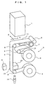
- Fig. 1 shows a sensor means 1, the details of which will be explained later and a means 2 for driving a test recording medium 3.
- a test pattern is printed on the test recording medium 3 with a printing head 4.
- the recording medium 3 is wound round rubber rolls 7,8 and several guide rolls 9 provided between a feeding roll 5 and a winding roll 6 to control the amount of recording paper to be fed and prevent it slipping. These rolls serve to maintain the tension of the recording paper.
- Blocks 12 and 13 are placed at a test pattern printing position 10 and a printed test pattern detecting position 11, respectively, to keep the recording medium 3 perpendicular to the printing head 4 and the center shaft of sensor means 1.
- Numeral 14 is a sensor for detecting the existence of recording medium 3. After the printing of a test pattern is completed, the pattern on the recording medium 3 is moved from the printing position 10 to the printed pattern detecting position 11 just under the sensor means 1 for its positioning.
- the sensor 1 After its mechanical zero setting, the sensor 1 scans along the X direction to capture an image of ink drops in column form in the test pattern on a group-by-group basis.
- the scanning method of sensor means 1 which is a driving device composed of a commonly available pulse motor and ball screws.
- Y indicates the direction in which the recording medium 3 moves at the detecting position 11.
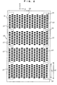
- Fig. 2 shows an example of a test pattern, which is made up of many ink drops 16 printed on the test recording medium 3 in given rows with the printing head 4.
- Each nozzle head prints in its own hue.
- each nozzle head is subjected to photographing of one row made up of eight ink drops 16 (area enclosed by inner dotted line) as one group 18 to check the nozzle head for any nozzle defect such as blinding.
- Range L1 for one group 18 is about 9 mm and range L2 for photographing is about 13 mm.
- the sensor means 1 of the device scans along X direction as indicated in the Figure.
- the test recording medium 3 moves along Y direction. Therefore, the first row is scanned along X direction on a group 18 basis and checked for any nozzle defect, and then the test recording medium 3 is moved along Y direction. Thereafter, the second row is scanned along X direction and checked in the same way as in the first row. A similar operation is repeated on the third and fourth rows. In this way, all the nozzles in the printing head 4 can be checked for any nozzle defect such as blinding with the sensor means 1 according to the method described below:
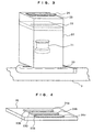
- the sensor means 1 is configured as shown in Fig. 3, consisting of a light source 19 made up of a U-shaped fluorescent lamp, a light converging lens 21 and a slit 22 provided in a box 20, and a light receiving element group 24 with filters 23 attached to the top of the box 20 so that all these components can move along X direction together.
- the light receiving element group 24 is composed of light receiving element arrays 24a, 24b and 24c arranged parallel in three rows as shown in Fig.4, each having a CCD made up of 2,592 photo-diodes per line with a RGB filter mounted on it (which consists of a red filter 23R, green-filter 23G or blue-filter 23B).
- 25 is a plate for mounting the light receiving element group 24.
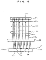
- Fig. 5 is a side view of the sensor means and Fig. 6 is its front view, showing the detecting principle of this invention.
- the light from the fluorescent lamp of light source 19 impinges and reflects from the recording medium 3 at the ink drops 16, where ink is applied, and white portions 3a where no ink is applied.
- Each of reflected light 26a and 26b is converged by the converging lens 21, passing through the slit 22, and then the filter 23, which cuts the light 26a reflected at the ink drop 16 or passes it only in a tiny amount.
- the light 26b reflected at the white portion 3a passes through the filter 23, reaching the CCD 27, the output voltage of which becomes high at the white portion 3a. For this reason, the output voltage of CCD 27 changes at the boundary point of the shape of ink drop 16 as shown in Fig.7 or 13.
- the first method of this invention is performed as follows.
- each ink drop 16 in a group 18 is recognized by binarization of its photographed image.
- the image processing method which is a publicly known device connected to the sensor means 1 by a cable for image processing according to the output signal from the light receiving means 24.
- the output voltage of CCD 27 changes at the boundary point of the shape of ink drop 16.
- the output voltage of CCD27 having such a characteristic curve as shown in Fig.7 is set with a threshold value c to determine points a and b as the boundary between bright and dark areas of the image by the scanning sensor means 1 along X direction at intervals of ⁇ m. This allows us to recognize the shape of each ink drop 16.
- Ink drop 16 ranges in size from 80 to 100 ⁇ m.
- the sampling interval ⁇ is 5 ⁇ m, which is so small that the above formula can represent an integration.
- the dot area drops in intensity and its width thus represents the CCD output below the threshold in pixels.
- SA Save ⁇ ⁇ /100 where ⁇ is approximately 80 %.
- Criterion SA is compared with the area Si of ink drop 16 determined as directed above. If the result of the comparison shows that the number of ink drops larger in area than the criterion are the same as specified in the group, the ink jetting can be judged as OK. If the result of the comparison shows the presence of any ink drop smaller in area than the criterion in the group, the ink jetting is to be judged as NG. This, in turn, allows us to detect failure in jetting of ink drops 16 present within the group 18, which means ink-jet nozzle blinding, enabling the operator to specify the nozzle that has undergone such failure.
- the shape of ink drop 16 determined as described above allows one edge position of the ink drop (or its starting position) such as 16a, 16b, and so on to be identified. More specifically, if the above-described recognition of the shape of ink drop 16 is performed with the position of the first dot ⁇ m or above in width stored in the memory, the starting edge position of the ink drop 16 can be identified. Each of the other ink drops in the group is processed in the same way to determine its starting edge position. The edge positions of the ink drops in the group thus determined are then processed to determine the difference between their maximum and minimum values as ⁇ X.
- the criterion for the judgment of the result is specified as ⁇ m.
- the said difference between the maximum and minimum values of the ink drop edge positions determined as ⁇ X is compared with the criterion ⁇ m. If the comparison shows that ⁇ X is less than ⁇ , the ink jetting can be regarded as OK in terms of ink drop location. If the comparison shows that ⁇ X is equal or larger than ⁇ ,the ink jetting is to be regarded as NG in terms of ink drop location. This allows us to detect any positional deviation of ink drop 16 in group 18 along X direction.
- the shape of ink drop 16 determined as described above allows the edge positions of the ink drop along Y direction such as 16f, 16g, and so on to be identified. More specifically, if the above-described recognition of the shape of ink drop 16 is performed with the position of the first dot ⁇ m or above in width stored in the memory, the top and bottom positions of the ink drop 16 can be identified.
- Each of the other ink drops in the group is processed in the same way to determine its top and bottom positions.
- the edge positions of each ink drop in the group thus determined are then processed as Y coordinates to determine the half of their sum, thereby calculating its center of gravity (center) position. This allows us to determine the center-to-center distance between two neighboring ink drops (d).
- the center-to-center distances between every two neighboring ink drops in the group thus determined are then processed to calculate the difference between their maximum value (dmax) and minimum value (dmin) as ⁇ Y.
- the criterion for the judgment of the result is specified as ⁇ m.
- the said difference between the maximum and minimum values of the ink drop center-to-center distances determined as ⁇ Y is compared with the criterion ⁇ m. If the comparison shows that ⁇ Y is less than ⁇ , the ink jetting can be regarded as OK in terms of ink drop location. If the comparison shows that ⁇ X is equal or larger than ⁇ , the ink jetting is to be regarded as NG in terms of ink drop location. This allows us to detect any positional deviation of ink drop 16 in group 18 along Y direction or the center-to-center distance is too wide or narrow.
- Each nozzle head in the printing head 4 prints in its own color.
- the present invention selects a proper RGB filter according to a digital signal SG4 from the CPU 28 to load the image data. More specifically, the system selects the red filter 23R for blue ink, the green filter 23G for yellow ink and the blue filter 23B for red ink to achieve a stable output voltage.
- the system has ink colors stored in the memory.
- the system deals with pale shade ink color, which develops with poor contrast, by multiple printing to enhance its absolute intensity, thereby increasing its sensitivity.
- the system selects the proper RGB filter according to the color of the ink to load its image data under the optimal contrast condition, which is converted by sensor means 1 into an analogue signal SG5 before being transmitted through the cable to the CPU28 where the signal is processed as mentioned above to judge the nozzle head for nozzle blinding, satellite of ink or ink drop mislocation. If the result of the judgment shows any defect in the nozzle head such as nozzle blinding, a digital signal SG1 is transmitted to an ink-jet printer 29 to indicate the occurrence of the defect, specifying the nozzle involved, which the operator can thus take remedial action on.
- Fig.13 (a) shows the effect of the filter on yellow ink
- Fig.13 (b) shows the effect of the filter on blue ink.
- Both Figures indicate that the variation in the output voltage with the filter is marked compared to that in the case without the filter, showing that the use of the filter is highly effective in enhancing the accuracy of the nozzle defect detection.
Landscapes
- Engineering & Computer Science (AREA)
- Quality & Reliability (AREA)
- Ink Jet (AREA)
- Particle Formation And Scattering Control In Inkjet Printers (AREA)
- Accessory Devices And Overall Control Thereof (AREA)
Abstract
Description
- This invention mainly relates to a method and device for detecting defects in nozzles of an ink-jet printer for cloth such as blinding of the nozzle, satellite of ink on the cloth and ink drop mislocation.
- Recent ink-jet printers for printing on cloth can express fine and subtle images. For this reason, the diameter of the nozzles which constitute the printing head gets smaller, and accordingly defects in the nozzles such as blinding and satellite of ink and ink drop mislocation happen often. Conventionally, when any of such nozzle defects occur, an operator judges it from the resultant nonconformity in the printed image by visual inspection or such defects are only found out at final inspection of the printed goods. However, experience and hard work are required to detect nonconformity in the image that is being printed. In addition, this may result in a large quantity of defective goods.
- Japanese Publication No. 2708439 proposes a solution to this problem. This describes the following method: a test pattern is printed on a test recording paper located outside of an original recording paper but near the original recording paper and read by a test pattern optical reading device mounted on the printing head (nozzle head). This is then compared with a pre-recorded standard pattern, thereby allowing an output failure of ink to be detected.
- Japanese Patent Publication No. 2712168 shows another technique for solving similar problems; all nozzles are caused to jet their inks at the same time. The jets are then to be photographed to calculate for each ink drop the position of its center gravity. This is then compared with a pre-determined standard centre of gravity and deviations between the two along the X and Y axes are calculated. From the deviations, the flying angle of the ink drop is derived and compared with the standard flying angle to evaluate the quality of the ink-jet.
- Japanese Patent Publication No. 6-198866 discloses a technique that involves photographing an ink-jet test pattern to evaluate its density signal, which density signal is then used to determine ink-jet failure or uneven density.
- Using comparisons of printing patterns such as mentioned in Japanese Patent Publication No. 2708439, it is difficult to judge accurately small deviations for each ink drop because the result of the judgement tends to be significantly affected by the threshold set against the standard pattern. On the other hand, in Japanese Patent Publication No. 2712168, the deviation is judged by comparison of the position of the center of gravity for each ink drop with a standard position of the center of gravity. But such an absolute comparison may result in detection failure caused by mislocation of the recording paper or other similar physical trouble with consequent deterioration of the detecting accuracy. The problem with Japanese Patent Publication No. 6-198866 is that it is difficult to judge uneven coloring especially for pale shades. Further, this technique does not cover detection of positional deviation of the ink drop. Attempts to use this technique for such detection in pale shades may involve further difficulties.
- A prior art document, EP-A-863012 discloses a method for detecting defects in nozzles in a printing head which comprises the steps of making an ink drop test pattern with the ink drops arranged in a column, scanning the pattern in the group to determine an area of each ink drop to calculate an average area and comparing the area of each drop to a criterion representing a given ratio of the average area to judge whether the ink jetting is normal or not. The steps are performed for all the nozzles in the head on a group by group basis.
- Another prior art document, EP-A-500281 discloses an ink jet nozzle defect detecting device having means for driving a test recording medium and sensor means for detecting a test pattern of ink drops printed on the test recording medium. The sensor means includes a light source and light receiving means for converging reflected light from a column of ink drops in the test pattern as one group, receiving the same through a slit and filter means. A scanning means scans the sensor means in a direction perpendicular to the ink drop column in the one group, image processing means processes an output signal from the light receiving means and a comparison means compares with a corresponding criterion to judge failures in the ink jetting.
- An object of the invention is to at least partially mitigate at least some of the problems of the prior art.
- According to the first aspect of the present invention there is provided a method for detecting defects in nozzles in a printing head comprising the steps of:
- photographing a plurality of ink drops in a test pattern as one group, the ink drops being preferably arranged in a column;
- recognizing the shape of each of the ink drops in said group to determine its edge position along a pre-determined direction; and
- comparing the difference between the maximum and minimum values of the ink drop edge positions along the pre-determined direction with a criterion to judge any positional deviation of any ink drop in said group along said pre-determined direction;
- said steps being performed for all the nozzles in said printing head on a group by group basis.
-
- According to a second aspect of the present invention there is provided a method for detecting defects in nozzles in a printing head comprising the steps of:
- photographing a plurality of ink drops in a test pattern as one group, the ink drops being preferably arranged in columns;
- recognizing the shape of each of the ink drops in said group and determining its edge positions along a pre-determined direction thereby identifying its center position;
- calculating the center-to-center distance between two neighboring ink drops in said group along said pre-determined direction; and
- comparing the difference between the maximum and minimum values of said center-to-center distances with a criterion to judge any position deviation of any ink drop in said group along the pre-determined direction;
- said steps being performed for all the nozzles in said printing head on a group by group basis.
-
- According to another aspect of the present invention there is provided an ink-jet nozzle defect detecting device comprising:
- means for driving a test recording medium, and sensor means for detecting a test pattern of ink drops printed on said test recording medium and means for judging any failure in an ink jetting about the test pattern;
- said sensor means including a light source and light receiving means for converging the reflected light from a column of ink drops existing in said test pattern as one group and receiving the same through slit means and filter means;
- scanning means for scanning said sensor means in a direction perpendicular to the ink drop column in said one group;
- image processing means for processing an output signal from said light receiving means;
- judging means for using at least one of areas, X direction edge positions and Y direction center-to-center distances of the ink drops in said group, which are determined from the shapes thereof, for comparison with a corresponding criterion to judge any failure in the ink jetting on a group by group basis;
- said filter means and light receiving means including light receiving element arrays receiving an image of the ink drop column at an optimal contrast by switching RGB filters arranged in three rows.
-
- According to yet another aspect of the present invention there is provided an ink-jet nozzle defect detecting device comprising:
- means for driving a test recording medium, and sensor means for detecting a test pattern of ink drops printed on said test recording medium and means for judging any failure in an ink jetting about the test pattern;
- said sensor means including a light source, and light receiving means for converging the reflected light from a column of ink drops existing in said test pattern as one group and receiving the same through slit means and filter means;
- scanning means for scanning said sensor means in a direction perpendicular to the ink drop column in said one group;
- image processing means for processing an output signal from said light receiving means; and
- judging means for comparing the difference between the maximum and minimum values of pre-determined direction edge positions obtained from the shape of each of the ink drops in said group with a criterion to judge any position deviation of any ink drop along the pre-determined direction on a group by a group basis.
-
- According to a still further aspect of the present invention there is provided an ink-jet nozzle defect detecting device comprising:
- means for driving a test recording medium and sensor means for detecting a test pattern of ink drops printed on said test recording medium, and means for judging any failure in an ink jetting about the test pattern;
- said sensor means including a light source and light receiving means for converging the reflected light from a column of ink drops existing in said test pattern as one group and receiving the same through slit means and filter means;
- scanning means for scanning said sensor means in a direction perpendicular to the ink drop column in said one group;
- image processing means for processing an output signal from said light receiving means; and
- judging means for comparing the differences between the maximum and minimum values of pre-determined direction center-to-center distances obtained from the shape of each of the ink drops in said group with a criterion to judge any position deviation of any ink drop along the pre-determined direction on a group by a group basis; wherein said filter means and said light receiving means include light receiving element arrays (24) receiving an image of the ink drop column at an optimal contrast by switching RGB filters (23R, 23G, 23B) arranged in three rows.
-
- An apparatus and various methods in which the invention is embodied will now be described by way of example only, and with reference to the following drawings, of which:
- Fig. 1 is a schematic diagram that shows an ink-jet nozzle defect detection device of this invention.
- Fig. 2 is an enlarged model diagram that shows one example of a test pattern printed by ink-jet nozzles.
- Fig. 3 is a perspective drawing that shows a sensor means of this invention's device.
- Fig. 4 is a perspective drawing that shows a light receiving means of the said sensor means.
- Fig. 5 is a side view of the sensor means that shows the detecting principle of this invention.
- Fig. 6 is a front view of the sensor means shown in Fig. 5.
- Fig. 7 is a drawing that shows the ink drop shape detecting method.
- Fig. 8 is a drawing that shows the method of sampling ink drop in detecting its shape.
- Fig. 9 is a drawing that shows the method of calculating the area of ink drop.
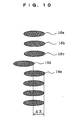
- Fig. 10 is a drawing that shows the method of judging a positional deviation of ink drop along X direction.
- Fig. 11 is a drawing that shows the method of judging a positional deviation of ink drop along Y direction.
- Fig. 12 is a block diagram of this invention's control device.
- Fig. 13 is a drawing that shows the effects of RGB filters.
-
- Fig. 1 shows a sensor means 1, the details of which will be explained later and a
means 2 for driving atest recording medium 3. A test pattern is printed on thetest recording medium 3 with aprinting head 4. For thetest recording medium 3, we use a special recording paper to enhance its detecting accuracy. The cloth to be actually used for production can be used but a recording paper that is less subject to ink bleeding or other similar trouble is more appropriate. - The
recording medium 3 is wound round rubber rolls 7,8 and several guide rolls 9 provided between a feedingroll 5 and a windingroll 6 to control the amount of recording paper to be fed and prevent it slipping. These rolls serve to maintain the tension of the recording paper.Blocks pattern printing position 10 and a printed testpattern detecting position 11, respectively, to keep therecording medium 3 perpendicular to theprinting head 4 and the center shaft of sensor means 1.Numeral 14 is a sensor for detecting the existence ofrecording medium 3. After the printing of a test pattern is completed, the pattern on therecording medium 3 is moved from theprinting position 10 to the printedpattern detecting position 11 just under the sensor means 1 for its positioning. After its mechanical zero setting, thesensor 1 scans along the X direction to capture an image of ink drops in column form in the test pattern on a group-by-group basis. There is no illustrative description given of the scanning method of sensor means 1, which is a driving device composed of a commonly available pulse motor and ball screws. In the Figure, Y indicates the direction in which therecording medium 3 moves at the detectingposition 11. - Fig. 2 shows an example of a test pattern, which is made up of many ink drops 16 printed on the
test recording medium 3 in given rows with theprinting head 4. In the example, theprinting head 4 has 32 nozzle heads (area 17 enclosed by outer dotted line represents one nozzle head.), each being composed of 8 x 2 rows = 16 nozzles (not shown). So, thisprinting head 4 has a total of 512 nozzles. Each nozzle head prints in its own hue. In this invention, each nozzle head is subjected to photographing of one row made up of eight ink drops 16 (area enclosed by inner dotted line) as onegroup 18 to check the nozzle head for any nozzle defect such as blinding. Range L1 for onegroup 18 is about 9 mm and range L2 for photographing is about 13 mm. - The sensor means 1 of the device scans along X direction as indicated in the Figure. The
test recording medium 3 moves along Y direction. Therefore, the first row is scanned along X direction on agroup 18 basis and checked for any nozzle defect, and then thetest recording medium 3 is moved along Y direction. Thereafter, the second row is scanned along X direction and checked in the same way as in the first row. A similar operation is repeated on the third and fourth rows. In this way, all the nozzles in theprinting head 4 can be checked for any nozzle defect such as blinding with the sensor means 1 according to the method described below: - The sensor means 1 is configured as shown in Fig. 3, consisting of a
light source 19 made up of a U-shaped fluorescent lamp, alight converging lens 21 and aslit 22 provided in abox 20, and a lightreceiving element group 24 withfilters 23 attached to the top of thebox 20 so that all these components can move along X direction together. - The light
receiving element group 24 is composed of light receivingelement arrays red filter 23R, green-filter 23G or blue-filter 23B). In the Figure, 25 is a plate for mounting the light receivingelement group 24. - Fig. 5 is a side view of the sensor means and Fig. 6 is its front view, showing the detecting principle of this invention.
- The light from the fluorescent lamp of
light source 19 impinges and reflects from therecording medium 3 at the ink drops 16, where ink is applied, andwhite portions 3a where no ink is applied. Each of reflected light 26a and 26b is converged by the converginglens 21, passing through theslit 22, and then thefilter 23, which cuts the light 26a reflected at theink drop 16 or passes it only in a tiny amount. The light 26b reflected at thewhite portion 3a passes through thefilter 23, reaching theCCD 27, the output voltage of which becomes high at thewhite portion 3a. For this reason, the output voltage ofCCD 27 changes at the boundary point of the shape ofink drop 16 as shown in Fig.7 or 13. - The first method of this invention is performed as follows.
- The shape of each
ink drop 16 in agroup 18 is recognized by binarization of its photographed image. There is no illustrative description given of the image processing method, which is a publicly known device connected to the sensor means 1 by a cable for image processing according to the output signal from the light receiving means 24. - As mentioned above, the output voltage of
CCD 27 changes at the boundary point of the shape ofink drop 16. The output voltage of CCD27 having such a characteristic curve as shown in Fig.7 is set with a threshold value c to determine points a and b as the boundary between bright and dark areas of the image by the scanning sensor means 1 along X direction at intervals of δµm. This allows us to recognize the shape of eachink drop 16. - After recognizing the shape of
ink drop 16, we calculate the area of each of the ink drops Si(i=1, 2, ...., n) and their average area Save. The area Si ofink drop 16 is calculated as follows: -
Ink drop 16 ranges in size from 80 to 100 µm. Area Si is calculated by sampling the ink drops at intervals of δ and adding their dot widths W0, W1, W2, ...., Wn as shown in Fig. 9. This can be expressed as the following formula: - The sampling interval δ is 5µm, which is so small that the above formula can represent an integration. The dot area drops in intensity and its width thus represents the CCD output below the threshold in pixels. Next, the average area of
ink drop 16 Save is calculated by dividing total sum of said Si by the quantity ofink drop 16 existing in onegroup 18 as expressed by the following formula:ink drop 16, which is 8 in this case. - To set tolerances for the judgment, we specify α% of the average area Save determined in 2 ○ as a criterion SA, which can be defined as the following formula:.
- Criterion SA is compared with the area Si of
ink drop 16 determined as directed above. If the result of the comparison shows that the number of ink drops larger in area than the criterion are the same as specified in the group, the ink jetting can be judged as OK. If the result of the comparison shows the presence of any ink drop smaller in area than the criterion in the group, the ink jetting is to be judged as NG. This, in turn, allows us to detect failure in jetting of ink drops 16 present within thegroup 18, which means ink-jet nozzle blinding, enabling the operator to specify the nozzle that has undergone such failure. - The second method of this invention is illustrated by reference to Fig.10.
- The shape of
ink drop 16 determined as described above allows one edge position of the ink drop (or its starting position) such as 16a, 16b, and so on to be identified. More specifically, if the above-described recognition of the shape ofink drop 16 is performed with the position of the first dot λµm or above in width stored in the memory, the starting edge position of theink drop 16 can be identified. Each of the other ink drops in the group is processed in the same way to determine its starting edge position. The edge positions of the ink drops in the group thus determined are then processed to determine the difference between their maximum and minimum values as ΔX. - The criterion for the judgment of the result is specified as βµm.
- The said difference between the maximum and minimum values of the ink drop edge positions determined as ΔX is compared with the criterion βµm. If the comparison shows that ΔX is less than β, the ink jetting can be regarded as OK in terms of ink drop location. If the comparison shows that ΔX is equal or larger than β,the ink jetting is to be regarded as NG in terms of ink drop location. This allows us to detect any positional deviation of
ink drop 16 ingroup 18 along X direction. - The third method of this invention is illustrated by reference to Fig. 11.
- The shape of
ink drop 16 determined as described above allows the edge positions of the ink drop along Y direction such as 16f, 16g, and so on to be identified. More specifically, if the above-described recognition of the shape ofink drop 16 is performed with the position of the first dot λµm or above in width stored in the memory, the top and bottom positions of theink drop 16 can be identified. Each of the other ink drops in the group is processed in the same way to determine its top and bottom positions. The edge positions of each ink drop in the group thus determined are then processed as Y coordinates to determine the half of their sum, thereby calculating its center of gravity (center) position. This allows us to determine the center-to-center distance between two neighboring ink drops (d). The center-to-center distances between every two neighboring ink drops in the group thus determined are then processed to calculate the difference between their maximum value (dmax) and minimum value (dmin) as ΔY. - The criterion for the judgment of the result is specified as γµm.
- The said difference between the maximum and minimum values of the ink drop center-to-center distances determined as ΔY is compared with the criterion γµm. If the comparison shows that ΔY is less than γ, the ink jetting can be regarded as OK in terms of ink drop location. If the comparison shows that ΔX is equal or larger than γ, the ink jetting is to be regarded as NG in terms of ink drop location. This allows us to detect any positional deviation of
ink drop 16 ingroup 18 along Y direction or the center-to-center distance is too wide or narrow. - The arithmetic operations in the first to third methods mentioned above, the comparison of the result of the operations with the criterion and the judgment of the result of the comparison are performed in the
CPU 28 shown in Fig. 12. - Each nozzle head in the
printing head 4 prints in its own color. As shown in Fig.12, therefore, the present invention selects a proper RGB filter according to a digital signal SG4 from theCPU 28 to load the image data. More specifically, the system selects thered filter 23R for blue ink, thegreen filter 23G for yellow ink and theblue filter 23B for red ink to achieve a stable output voltage. The system has ink colors stored in the memory. In addition, the system deals with pale shade ink color, which develops with poor contrast, by multiple printing to enhance its absolute intensity, thereby increasing its sensitivity. In this way, the system selects the proper RGB filter according to the color of the ink to load its image data under the optimal contrast condition, which is converted by sensor means 1 into an analogue signal SG5 before being transmitted through the cable to the CPU28 where the signal is processed as mentioned above to judge the nozzle head for nozzle blinding, satellite of ink or ink drop mislocation. If the result of the judgment shows any defect in the nozzle head such as nozzle blinding, a digital signal SG1 is transmitted to an ink-jet printer 29 to indicate the occurrence of the defect, specifying the nozzle involved, which the operator can thus take remedial action on. - Fig.13 (a) shows the effect of the filter on yellow ink, while Fig.13 (b) shows the effect of the filter on blue ink. Both Figures indicate that the variation in the output voltage with the filter is marked compared to that in the case without the filter, showing that the use of the filter is highly effective in enhancing the accuracy of the nozzle defect detection.
Claims (11)
- A method for detecting defects in nozzles in a printing head comprising the steps of:photographing a plurality of ink drops in a test pattern as one group, the ink drops being preferably arranged in a column;recognizing the shape of each of the ink drops in said group to determine its edge position along a pre-determined direction; andcomparing the difference between the maximum and minimum values of the ink drop edge positions along the pre-determined direction with a criterion to judge any positional deviation of any ink drop in said group along said pre-determined direction;said steps being performed for all the nozzles in said printing head on a group by group basis.
- A method as claimed in claim 1, wherein the pre-determined direction is a scanning direction of the printing head.
- A method for detecting defects in nozzles in a printing head comprising the steps of:photographing a plurality of ink drops in a test pattern as one group, the ink drops being preferably arranged in columns;recognizing the shape of each of the ink drops in said group and determining its edge positions along a pre-determined direction thereby identifying its center position;calculating the center-to-center distance between two neighboring ink drops in said group along said pre-determined direction; andcomparing the difference between the maximum and minimum values of said center-to-center distances with a criterion to judge any position deviation of any ink drop in said group along the pre-determined direction;said steps being performed for all the nozzles in said printing head on a group by group basis.
- A method as claimed in claim 3, wherein the pre-determined direction is a direction perpendicular to a scanning direction of the printing head.
- A method according to any one of claims 1 to 4, wherein in loading the image of ink drops in said group, RGB filters in a light receiving unit are selectively used according to the ink color of said group to achieve said loading with the optimum contrast in said image.
- An ink-jet nozzle defect detecting device comprising:means (2) for driving a test recording medium (3), and sensor means (1) for detecting a test pattern (15) of ink drops (16) printed on said test recording medium (3) and means (28) for judging any failure in an ink jetting about the test pattern (15);said sensor means (1) including a light source (19) and light receiving means (24) for converging the reflected light from a column of ink drops (16) existing in said test pattern as one group (18) and receiving the same through slit means (22) and filter means (23);scanning means for scanning said sensor means (1) in a direction perpendicular to the ink drop column in said one group (18);image processing means for processing an output signal from said light receiving means (24);judging means (28) for using at least one of areas, X direction edge positions and Y direction center-to-center distances of the ink drops (16) in said group (18), which are determined from the shapes thereof, for comparison with a corresponding criterion to judge any failure in the ink jetting on a group by group basis;said filter means and light receiving means including light receiving element arrays (24) receiving an image of the ink drop column at an optimal contrast by switching RGB filters (23R, 23G, 23B) arranged in three rows.
- An ink-jet nozzle defect detecting device comprising:means (2) for driving a test recording medium (3), and sensor means (1) for detecting a test pattern (15) of ink drops (16) printed on said test recording medium (3) and means (28) for judging any failure in an ink jetting about the test pattern (15);said sensor means (1) including a light source (19), and light receiving means (24) for converging the reflected light from a column of ink drops (16) existing in said test pattern as one group (18) and receiving the same through slit means (22) and filter means (23);scanning means for scanning said sensor means (1) in a direction perpendicular to the ink drop column in said one group (18);image processing means for processing an output signal from said light receiving means (24); andjudging means (28) for comparing the difference between the maximum and minimum values of pre-determined direction edge positions obtained from the shape of each of the ink drops (16) in said group (18) with a criterion to judge any position deviation of any ink drop along the pre-determined direction on a group by a group basis.
- An ink jet nozzle defect detecting device according to claim 7, wherein the pre-determined direction is a X direction.
- An ink-jet nozzle defect detecting device comprising:wherein said filter means and said light receiving means include light receiving element arrays (24) receiving an image of the ink drop column at an optimal contrast by switching RGB filters (23R, 23G, 23B) arranged in three rows.means (2) for driving a test recording medium (3) and sensor means (1) for detecting a test pattern (15) of ink drops (16) printed on said test recording medium (13), and means (28) for judging any failure in an ink jetting about the test pattern (15);said sensor means (1) including a light source (19) and light receiving means (24) for converging the reflected light from a column of ink drops (16) existing in said test pattern as one group (18) and receiving the same through slit means (22) and filter means (23);scanning means for scanning said sensor means (1) in a direction perpendicular to the ink drop column in said one group (18);image processing means for processing an output signal from said light receiving means (24); andjudging means (28) for comparing the differences between the maximum and minimum values of pre-determined direction center-to-center distances obtained from the shape of each of the ink drops (16) in said group (18) with a criterion to judge any position deviation of any ink drop along the pre-determined direction on a group by a group basis;
- An ink jet nozzle defect detecting device according to claim 9, wherein the pre-determined direction is a Y direction.
- An ink jet nozzle defect detecting device according to claims 7 or 8, wherein said filter means and said light receiving means include light receiving element arrays (24) receiving an image of the ink drop column at an optimal contrast by switching RGB filters (23R, 23G, 23B) arranged in three rows.
Applications Claiming Priority (2)
| Application Number | Priority Date | Filing Date | Title |
|---|---|---|---|
| JP26788398A JP4258685B2 (en) | 1998-09-22 | 1998-09-22 | Inkjet nozzle defect detection method and apparatus |
| JP26788398 | 1998-09-22 |
Publications (3)
| Publication Number | Publication Date |
|---|---|
| EP0988990A2 EP0988990A2 (en) | 2000-03-29 |
| EP0988990A3 EP0988990A3 (en) | 2000-10-11 |
| EP0988990B1 true EP0988990B1 (en) | 2004-03-24 |
Family
ID=17450964
Family Applications (1)
| Application Number | Title | Priority Date | Filing Date |
|---|---|---|---|
| EP99307507A Expired - Lifetime EP0988990B1 (en) | 1998-09-22 | 1999-09-22 | Ink-jet printer nozzle defect detection method and device |
Country Status (5)
| Country | Link |
|---|---|
| EP (1) | EP0988990B1 (en) |
| JP (1) | JP4258685B2 (en) |
| AT (1) | ATE262416T1 (en) |
| DE (1) | DE69915755T2 (en) |
| ES (1) | ES2214817T3 (en) |
Cited By (1)
| Publication number | Priority date | Publication date | Assignee | Title |
|---|---|---|---|---|
| CN109849521A (en) * | 2019-01-15 | 2019-06-07 | 北大方正集团有限公司 | Detection method, device, equipment and the computer readable storage medium of spray orifice blocking |
Families Citing this family (16)
| Publication number | Priority date | Publication date | Assignee | Title |
|---|---|---|---|---|
| US20020171697A1 (en) * | 2001-04-04 | 2002-11-21 | Eyal Gargir | Method and system for compensating for banding defects in inkjet printers |
| TW200403598A (en) * | 2002-03-29 | 2004-03-01 | Olympus Optical Co | Test figure, geometric feature analyzing system, geometric feature analyzing-method, printer, and inkjet printer |
| GB0326733D0 (en) * | 2003-11-17 | 2003-12-17 | Fujifilm Electronic Imaging | Improvements relating to inkjet printers |
| JP2006088487A (en) * | 2004-09-22 | 2006-04-06 | Fuji Xerox Co Ltd | Method of inspecting discharge of ink for inkjet recording and/or treatment liquid |
| DE602008006517D1 (en) | 2008-02-25 | 2011-06-09 | Oce Tech Bv | Method of detecting misdirected nozzles in an inkjet printer |
| JP5729105B2 (en) * | 2011-04-19 | 2015-06-03 | セイコーエプソン株式会社 | Droplet ejecting apparatus and droplet ejecting method |
| JP2013059877A (en) * | 2011-09-12 | 2013-04-04 | Seiren Co Ltd | Method for detecting discharge defects of inkjet nozzle |
| CN106457835B (en) * | 2014-07-25 | 2018-05-18 | 惠普发展公司有限责任合伙企业 | Pair sort out with the corresponding vertical edge of half tone image |
| US10545844B2 (en) | 2017-09-29 | 2020-01-28 | Ricoh Company, Ltd. | Print verification system that reports defective printheads |
| US11565532B2 (en) * | 2020-08-21 | 2023-01-31 | Casio Computer Co., Ltd. | Printing apparatus, printing control method, and nontransitory computer-readable recording medium |
| JP7283493B2 (en) * | 2020-08-21 | 2023-05-30 | カシオ計算機株式会社 | PRINTING DEVICE, PRINT CONTROL METHOD AND PROGRAM |
| CN115214234A (en) * | 2021-04-21 | 2022-10-21 | 株式会社村田制作所 | Evaluation device and inkjet printing device of inkjet printing device |
| US11850861B2 (en) * | 2021-05-24 | 2023-12-26 | Xerox Corporation | System and method for detecting and remediating split inkjets in an inkjet printer during printing operations |
| CN114211878B (en) * | 2021-12-13 | 2023-10-17 | 苏州华星光电技术有限公司 | Detection method, storage medium and equipment for ink-jet printing ink |
| CN116653433B (en) * | 2022-02-17 | 2026-05-12 | 森大(深圳)技术有限公司 | Method, device, equipment and storage medium for detecting automatic ink supply air pressure of spray head in real time |
| US12528099B2 (en) | 2022-07-28 | 2026-01-20 | Ricoh Company, Ltd. | Liquid discharge apparatus and liquid discharge method |
Family Cites Families (7)
| Publication number | Priority date | Publication date | Assignee | Title |
|---|---|---|---|---|
| US4675696A (en) * | 1982-04-07 | 1987-06-23 | Canon Kabushiki Kaisha | Recording apparatus |
| JP2712168B2 (en) | 1987-02-27 | 1998-02-10 | 富士通株式会社 | Inkjet evaluation method and evaluation test device |
| JP2708439B2 (en) | 1987-11-17 | 1998-02-04 | キヤノン株式会社 | Inkjet printer |
| JP3049663B2 (en) * | 1991-02-20 | 2000-06-05 | キヤノン株式会社 | Recording device and recording method |
| JP3278218B2 (en) | 1992-12-28 | 2002-04-30 | キヤノン株式会社 | INK JET RECORDING APPARATUS AND PROCESS FOR PRODUCING INK JET RECORDINGS |
| US6352331B1 (en) * | 1997-03-04 | 2002-03-05 | Hewlett-Packard Company | Detection of non-firing printhead nozzles by optical scanning of a test pattern |
| US5748330A (en) * | 1997-05-05 | 1998-05-05 | Xerox Corporation | Method of calibrating a digital printer using component test patches and the yule-nielsen equation |
-
1998
- 1998-09-22 JP JP26788398A patent/JP4258685B2/en not_active Expired - Fee Related
-
1999
- 1999-09-22 EP EP99307507A patent/EP0988990B1/en not_active Expired - Lifetime
- 1999-09-22 DE DE1999615755 patent/DE69915755T2/en not_active Expired - Lifetime
- 1999-09-22 AT AT99307507T patent/ATE262416T1/en not_active IP Right Cessation
- 1999-09-22 ES ES99307507T patent/ES2214817T3/en not_active Expired - Lifetime
Cited By (1)
| Publication number | Priority date | Publication date | Assignee | Title |
|---|---|---|---|---|
| CN109849521A (en) * | 2019-01-15 | 2019-06-07 | 北大方正集团有限公司 | Detection method, device, equipment and the computer readable storage medium of spray orifice blocking |
Also Published As
| Publication number | Publication date |
|---|---|
| JP4258685B2 (en) | 2009-04-30 |
| DE69915755D1 (en) | 2004-04-29 |
| EP0988990A2 (en) | 2000-03-29 |
| JP2000094655A (en) | 2000-04-04 |
| ATE262416T1 (en) | 2004-04-15 |
| ES2214817T3 (en) | 2004-09-16 |
| DE69915755T2 (en) | 2005-01-13 |
| EP0988990A3 (en) | 2000-10-11 |
Similar Documents
| Publication | Publication Date | Title |
|---|---|---|
| EP0988990A2 (en) | Ink-jet printer nozzle defect detection method and device | |
| US20020033851A1 (en) | Process and apparatus for the printing of digital image information | |
| US6352331B1 (en) | Detection of non-firing printhead nozzles by optical scanning of a test pattern | |
| KR101705538B1 (en) | System and method for detecting weak and missing inkjets in an inkjet printer using image data of printed documents without a priori knowledge of the documents | |
| US20070040878A1 (en) | Printing apparatus, method of inspecting nozzles for abnormalities, and program | |
| JP2016026918A (en) | Nozzle inspection apparatus and image forming apparatus | |
| KR20220011657A (en) | Nozzle defect compensation and non-uniformity compensation in inkjet printing | |
| US7099024B2 (en) | Recording position adjusting pattern forming method, image recording position adjusting method and image recording apparatus | |
| JP2016027319A (en) | Imaging device, image forming apparatus, and dirt inspection method | |
| US7561304B2 (en) | Method of judging whether or not darkness of foreign matter has been read, method of calculating representative value of darkness of test pattern, and apparatus that judges whether or not darkness of foreign matter has been read | |
| JPH11151801A (en) | Color optical sensor and printing paper surface inspection apparatus using the same | |
| US20090262373A1 (en) | Method of calculating correction value and liquid ejecting apparatus | |
| US7232200B2 (en) | Image forming apparatus and method for forming image | |
| US20060119633A1 (en) | Method of calibrating inkjet print head | |
| US20050057595A1 (en) | Method and printer for applying an ink image to a receiving material | |
| JP2020203428A (en) | Method and device for image inspection, program, and image recording system | |
| JP6223074B2 (en) | Inkjet recording head color mixing detection method, color mixing detection apparatus, and recording apparatus | |
| EP2484533B1 (en) | Printer | |
| US11014388B2 (en) | Test pattern formation method, landing deviation amount acquisition method, and recording device | |
| JP7696950B2 (en) | Recording device, recording method, and program | |
| JP6292916B2 (en) | Inkjet recording head color mixing inspection method and recording apparatus | |
| JP2016060066A (en) | Nozzle inspection device, image forming device, and nozzle inspection method | |
| JPH08145914A (en) | Detecting equipment of defect of lumber by one-dimensional tv camera | |
| JPH09254393A (en) | Inkjet printer output defect detection device | |
| JP2017205915A (en) | Liquid discharge device, adjustment method, and program |
Legal Events
| Date | Code | Title | Description |
|---|---|---|---|
| PUAI | Public reference made under article 153(3) epc to a published international application that has entered the european phase |
Free format text: ORIGINAL CODE: 0009012 |
|
| AK | Designated contracting states |
Kind code of ref document: A2 Designated state(s): AT BE CH CY DE DK ES FI FR GB GR IE IT LI LU MC NL PT SE |
|
| AX | Request for extension of the european patent |
Free format text: AL;LT;LV;MK;RO;SI |
|
| PUAL | Search report despatched |
Free format text: ORIGINAL CODE: 0009013 |
|
| AK | Designated contracting states |
Kind code of ref document: A3 Designated state(s): AT BE CH CY DE DK ES FI FR GB GR IE IT LI LU MC NL PT SE |
|
| AX | Request for extension of the european patent |
Free format text: AL;LT;LV;MK;RO;SI |
|
| 17P | Request for examination filed |
Effective date: 20001110 |
|
| AKX | Designation fees paid |
Free format text: AT BE CH CY DE DK ES FI FR GB GR IE IT LI LU MC NL PT SE |
|
| 17Q | First examination report despatched |
Effective date: 20010903 |
|
| GRAP | Despatch of communication of intention to grant a patent |
Free format text: ORIGINAL CODE: EPIDOSNIGR1 |
|
| GRAS | Grant fee paid |
Free format text: ORIGINAL CODE: EPIDOSNIGR3 |
|
| GRAA | (expected) grant |
Free format text: ORIGINAL CODE: 0009210 |
|
| AK | Designated contracting states |
Kind code of ref document: B1 Designated state(s): AT BE CH CY DE DK ES FI FR GB GR IE IT LI LU MC NL PT SE |
|
| PG25 | Lapsed in a contracting state [announced via postgrant information from national office to epo] |
Ref country code: NL Free format text: LAPSE BECAUSE OF FAILURE TO SUBMIT A TRANSLATION OF THE DESCRIPTION OR TO PAY THE FEE WITHIN THE PRESCRIBED TIME-LIMIT Effective date: 20040324 Ref country code: LI Free format text: LAPSE BECAUSE OF FAILURE TO SUBMIT A TRANSLATION OF THE DESCRIPTION OR TO PAY THE FEE WITHIN THE PRESCRIBED TIME-LIMIT Effective date: 20040324 Ref country code: FI Free format text: LAPSE BECAUSE OF FAILURE TO SUBMIT A TRANSLATION OF THE DESCRIPTION OR TO PAY THE FEE WITHIN THE PRESCRIBED TIME-LIMIT Effective date: 20040324 Ref country code: CY Free format text: LAPSE BECAUSE OF FAILURE TO SUBMIT A TRANSLATION OF THE DESCRIPTION OR TO PAY THE FEE WITHIN THE PRESCRIBED TIME-LIMIT Effective date: 20040324 Ref country code: CH Free format text: LAPSE BECAUSE OF FAILURE TO SUBMIT A TRANSLATION OF THE DESCRIPTION OR TO PAY THE FEE WITHIN THE PRESCRIBED TIME-LIMIT Effective date: 20040324 Ref country code: AT Free format text: LAPSE BECAUSE OF FAILURE TO SUBMIT A TRANSLATION OF THE DESCRIPTION OR TO PAY THE FEE WITHIN THE PRESCRIBED TIME-LIMIT Effective date: 20040324 |
|
| REG | Reference to a national code |
Ref country code: GB Ref legal event code: FG4D |
|
| REG | Reference to a national code |
Ref country code: CH Ref legal event code: EP |
|
| REG | Reference to a national code |
Ref country code: IE Ref legal event code: FG4D |
|
| REF | Corresponds to: |
Ref document number: 69915755 Country of ref document: DE Date of ref document: 20040429 Kind code of ref document: P |
|
| PG25 | Lapsed in a contracting state [announced via postgrant information from national office to epo] |
Ref country code: SE Free format text: LAPSE BECAUSE OF FAILURE TO SUBMIT A TRANSLATION OF THE DESCRIPTION OR TO PAY THE FEE WITHIN THE PRESCRIBED TIME-LIMIT Effective date: 20040624 Ref country code: GR Free format text: LAPSE BECAUSE OF FAILURE TO SUBMIT A TRANSLATION OF THE DESCRIPTION OR TO PAY THE FEE WITHIN THE PRESCRIBED TIME-LIMIT Effective date: 20040624 Ref country code: DK Free format text: LAPSE BECAUSE OF FAILURE TO SUBMIT A TRANSLATION OF THE DESCRIPTION OR TO PAY THE FEE WITHIN THE PRESCRIBED TIME-LIMIT Effective date: 20040624 |
|
| NLV1 | Nl: lapsed or annulled due to failure to fulfill the requirements of art. 29p and 29m of the patents act | ||
| REG | Reference to a national code |
Ref country code: ES Ref legal event code: FG2A Ref document number: 2214817 Country of ref document: ES Kind code of ref document: T3 |
|
| PG25 | Lapsed in a contracting state [announced via postgrant information from national office to epo] |
Ref country code: LU Free format text: LAPSE BECAUSE OF NON-PAYMENT OF DUE FEES Effective date: 20040922 Ref country code: IE Free format text: LAPSE BECAUSE OF NON-PAYMENT OF DUE FEES Effective date: 20040922 |
|
| PG25 | Lapsed in a contracting state [announced via postgrant information from national office to epo] |
Ref country code: MC Free format text: LAPSE BECAUSE OF NON-PAYMENT OF DUE FEES Effective date: 20040930 |
|
| REG | Reference to a national code |
Ref country code: CH Ref legal event code: PL |
|
| ET | Fr: translation filed | ||
| PLBE | No opposition filed within time limit |
Free format text: ORIGINAL CODE: 0009261 |
|
| STAA | Information on the status of an ep patent application or granted ep patent |
Free format text: STATUS: NO OPPOSITION FILED WITHIN TIME LIMIT |
|
| 26N | No opposition filed |
Effective date: 20041228 |
|
| REG | Reference to a national code |
Ref country code: IE Ref legal event code: MM4A |
|
| PG25 | Lapsed in a contracting state [announced via postgrant information from national office to epo] |
Ref country code: PT Free format text: LAPSE BECAUSE OF NON-PAYMENT OF DUE FEES Effective date: 20040824 |
|
| REG | Reference to a national code |
Ref country code: FR Ref legal event code: PLFP Year of fee payment: 17 |
|
| PGFP | Annual fee paid to national office [announced via postgrant information from national office to epo] |
Ref country code: ES Payment date: 20150810 Year of fee payment: 17 Ref country code: DE Payment date: 20150916 Year of fee payment: 17 Ref country code: GB Payment date: 20150916 Year of fee payment: 17 |
|
| PGFP | Annual fee paid to national office [announced via postgrant information from national office to epo] |
Ref country code: BE Payment date: 20150911 Year of fee payment: 17 Ref country code: FR Payment date: 20150811 Year of fee payment: 17 |
|
| PGFP | Annual fee paid to national office [announced via postgrant information from national office to epo] |
Ref country code: IT Payment date: 20150925 Year of fee payment: 17 |
|
| PG25 | Lapsed in a contracting state [announced via postgrant information from national office to epo] |
Ref country code: BE Free format text: LAPSE BECAUSE OF NON-PAYMENT OF DUE FEES Effective date: 20160930 |
|
| REG | Reference to a national code |
Ref country code: DE Ref legal event code: R119 Ref document number: 69915755 Country of ref document: DE |
|
| GBPC | Gb: european patent ceased through non-payment of renewal fee |
Effective date: 20160922 |
|
| REG | Reference to a national code |
Ref country code: FR Ref legal event code: ST Effective date: 20170531 |
|
| PG25 | Lapsed in a contracting state [announced via postgrant information from national office to epo] |
Ref country code: GB Free format text: LAPSE BECAUSE OF NON-PAYMENT OF DUE FEES Effective date: 20160922 Ref country code: FR Free format text: LAPSE BECAUSE OF NON-PAYMENT OF DUE FEES Effective date: 20160930 Ref country code: DE Free format text: LAPSE BECAUSE OF NON-PAYMENT OF DUE FEES Effective date: 20170401 |
|
| PG25 | Lapsed in a contracting state [announced via postgrant information from national office to epo] |
Ref country code: IT Free format text: LAPSE BECAUSE OF NON-PAYMENT OF DUE FEES Effective date: 20160922 |
|
| REG | Reference to a national code |
Ref country code: BE Ref legal event code: MM Effective date: 20160930 |
|
| PG25 | Lapsed in a contracting state [announced via postgrant information from national office to epo] |
Ref country code: ES Free format text: LAPSE BECAUSE OF NON-PAYMENT OF DUE FEES Effective date: 20160923 |
|
| REG | Reference to a national code |
Ref country code: ES Ref legal event code: FD2A Effective date: 20181119 |