EP0988776B1 - A compact modular in-the-ear hearing aid - Google Patents
A compact modular in-the-ear hearing aid Download PDFInfo
- Publication number
- EP0988776B1 EP0988776B1 EP98914845A EP98914845A EP0988776B1 EP 0988776 B1 EP0988776 B1 EP 0988776B1 EP 98914845 A EP98914845 A EP 98914845A EP 98914845 A EP98914845 A EP 98914845A EP 0988776 B1 EP0988776 B1 EP 0988776B1
- Authority
- EP
- European Patent Office
- Prior art keywords
- battery
- socket part
- hearing aid
- faceplate
- recess
- Prior art date
- Legal status (The legal status is an assumption and is not a legal conclusion. Google has not performed a legal analysis and makes no representation as to the accuracy of the status listed.)
- Expired - Lifetime
Links
Images


Classifications
-
- H—ELECTRICITY
- H04—ELECTRIC COMMUNICATION TECHNIQUE
- H04R—LOUDSPEAKERS, MICROPHONES, GRAMOPHONE PICK-UPS OR LIKE ACOUSTIC ELECTROMECHANICAL TRANSDUCERS; DEAF-AID SETS; PUBLIC ADDRESS SYSTEMS
- H04R25/00—Deaf-aid sets, i.e. electro-acoustic or electro-mechanical hearing aids; Electric tinnitus maskers providing an auditory perception
- H04R25/65—Housing parts, e.g. shells, tips or moulds, or their manufacture
-
- H—ELECTRICITY
- H04—ELECTRIC COMMUNICATION TECHNIQUE
- H04R—LOUDSPEAKERS, MICROPHONES, GRAMOPHONE PICK-UPS OR LIKE ACOUSTIC ELECTROMECHANICAL TRANSDUCERS; DEAF-AID SETS; PUBLIC ADDRESS SYSTEMS
- H04R25/00—Deaf-aid sets, i.e. electro-acoustic or electro-mechanical hearing aids; Electric tinnitus maskers providing an auditory perception
- H04R25/60—Mounting or interconnection of hearing aid parts, e.g. inside tips, housings or to ossicles
- H04R25/602—Mounting or interconnection of hearing aid parts, e.g. inside tips, housings or to ossicles of batteries
-
- H—ELECTRICITY
- H04—ELECTRIC COMMUNICATION TECHNIQUE
- H04R—LOUDSPEAKERS, MICROPHONES, GRAMOPHONE PICK-UPS OR LIKE ACOUSTIC ELECTROMECHANICAL TRANSDUCERS; DEAF-AID SETS; PUBLIC ADDRESS SYSTEMS
- H04R25/00—Deaf-aid sets, i.e. electro-acoustic or electro-mechanical hearing aids; Electric tinnitus maskers providing an auditory perception
- H04R25/60—Mounting or interconnection of hearing aid parts, e.g. inside tips, housings or to ossicles
- H04R25/604—Mounting or interconnection of hearing aid parts, e.g. inside tips, housings or to ossicles of acoustic or vibrational transducers
-
- H—ELECTRICITY
- H04—ELECTRIC COMMUNICATION TECHNIQUE
- H04R—LOUDSPEAKERS, MICROPHONES, GRAMOPHONE PICK-UPS OR LIKE ACOUSTIC ELECTROMECHANICAL TRANSDUCERS; DEAF-AID SETS; PUBLIC ADDRESS SYSTEMS
- H04R25/00—Deaf-aid sets, i.e. electro-acoustic or electro-mechanical hearing aids; Electric tinnitus maskers providing an auditory perception
- H04R25/60—Mounting or interconnection of hearing aid parts, e.g. inside tips, housings or to ossicles
- H04R25/609—Mounting or interconnection of hearing aid parts, e.g. inside tips, housings or to ossicles of circuitry
-
- H—ELECTRICITY
- H04—ELECTRIC COMMUNICATION TECHNIQUE
- H04R—LOUDSPEAKERS, MICROPHONES, GRAMOPHONE PICK-UPS OR LIKE ACOUSTIC ELECTROMECHANICAL TRANSDUCERS; DEAF-AID SETS; PUBLIC ADDRESS SYSTEMS
- H04R25/00—Deaf-aid sets, i.e. electro-acoustic or electro-mechanical hearing aids; Electric tinnitus maskers providing an auditory perception
- H04R25/65—Housing parts, e.g. shells, tips or moulds, or their manufacture
- H04R25/652—Ear tips; Ear moulds
-
- H—ELECTRICITY
- H04—ELECTRIC COMMUNICATION TECHNIQUE
- H04R—LOUDSPEAKERS, MICROPHONES, GRAMOPHONE PICK-UPS OR LIKE ACOUSTIC ELECTROMECHANICAL TRANSDUCERS; DEAF-AID SETS; PUBLIC ADDRESS SYSTEMS
- H04R25/00—Deaf-aid sets, i.e. electro-acoustic or electro-mechanical hearing aids; Electric tinnitus maskers providing an auditory perception
- H04R25/65—Housing parts, e.g. shells, tips or moulds, or their manufacture
- H04R25/658—Manufacture of housing parts
-
- H—ELECTRICITY
- H04—ELECTRIC COMMUNICATION TECHNIQUE
- H04R—LOUDSPEAKERS, MICROPHONES, GRAMOPHONE PICK-UPS OR LIKE ACOUSTIC ELECTROMECHANICAL TRANSDUCERS; DEAF-AID SETS; PUBLIC ADDRESS SYSTEMS
- H04R2225/00—Details of deaf aids covered by H04R25/00, not provided for in any of its subgroups
- H04R2225/025—In the ear hearing aids [ITE] hearing aids
-
- H—ELECTRICITY
- H04—ELECTRIC COMMUNICATION TECHNIQUE
- H04R—LOUDSPEAKERS, MICROPHONES, GRAMOPHONE PICK-UPS OR LIKE ACOUSTIC ELECTROMECHANICAL TRANSDUCERS; DEAF-AID SETS; PUBLIC ADDRESS SYSTEMS
- H04R2225/00—Details of deaf aids covered by H04R25/00, not provided for in any of its subgroups
- H04R2225/57—Aspects of electrical interconnection between hearing aid parts
-
- H—ELECTRICITY
- H04—ELECTRIC COMMUNICATION TECHNIQUE
- H04R—LOUDSPEAKERS, MICROPHONES, GRAMOPHONE PICK-UPS OR LIKE ACOUSTIC ELECTROMECHANICAL TRANSDUCERS; DEAF-AID SETS; PUBLIC ADDRESS SYSTEMS
- H04R25/00—Deaf-aid sets, i.e. electro-acoustic or electro-mechanical hearing aids; Electric tinnitus maskers providing an auditory perception
- H04R25/60—Mounting or interconnection of hearing aid parts, e.g. inside tips, housings or to ossicles
- H04R25/603—Mounting or interconnection of hearing aid parts, e.g. inside tips, housings or to ossicles of mechanical or electronic switches or control elements
-
- Y—GENERAL TAGGING OF NEW TECHNOLOGICAL DEVELOPMENTS; GENERAL TAGGING OF CROSS-SECTIONAL TECHNOLOGIES SPANNING OVER SEVERAL SECTIONS OF THE IPC; TECHNICAL SUBJECTS COVERED BY FORMER USPC CROSS-REFERENCE ART COLLECTIONS [XRACs] AND DIGESTS
- Y10—TECHNICAL SUBJECTS COVERED BY FORMER USPC
- Y10T—TECHNICAL SUBJECTS COVERED BY FORMER US CLASSIFICATION
- Y10T29/00—Metal working
- Y10T29/49—Method of mechanical manufacture
- Y10T29/4957—Sound device making
- Y10T29/49572—Hearing aid component making
Definitions
- the present invention relates to a modular hearing aid for arrangement in a user's ear, ITE, particularly completely inside the ear canal, CIC, comprising a hollow plug adapted to the ear canal and having a generally irregular conical shape and an outward opening which is covered by a faceplate in which a recess is formed for removable arrangement of a battery as well as an electronic module comprising a microphone and further parts composed of a signal processing part and a sound reproducer.
- hearing aids in a so-called BTE design for arrangement behind a user's ear are usually manufactured with a housing of a size that allows relatively easy separation for replacement of battery and possibly removal of electronic components for repair, etc.
- hearing aids of the above designs i.e., of a so-called ITE design for arrangement in the ear, normally in the funnel-shaped outer part of the ear canal, or of a so-called CIC design for arrangement completely inside the ear canal, require a very compact design of the housing or plug of the hearing aid to allow it partly to be arranged in the ear canal, partly to house the components necessary for operation of the hearing aid, such as battery and electronic components for sound reception, signal processing and sound reproduction.
- hearing aids are therefore normally built up by joining together a plug or shell, which is adapted in shape and dimensions to the ear canal of the actual user and has an external faceplate to which the electronic components are glued or otherwise fastened so that by gluing of the faceplate to the user-adapted plug or shell they are localized therein in a protected manner.
- conventional hearing aids of this type such as are known from, e.g., EP A2-0 311 233 and US-A-4,680,799, it is therefore usually necessary in connection with replacement or repair of electronic components to break the shell or the faceplate by milling or in any other way, which renders repairs difficult and more expensive and means that the shell and/or the faceplate must be re-established after repair.
- This insert part or mounting plate is, however, relatively large compared with the overall size of the faceplate and therefore requires a corresponding increase of the size of the recess, which limits the possibilities of final adaptation of the external contour of the faceplate, for example by buffing in connection with joining the faceplate with the user-adapted shell or plug, to an undesired degree. Furthermore, the manufacturing of these known hearing aids is made more complicated and expensive by the requirement for a separate insert part or mounting plate for the electronic components.
- an electronic module is removably fastened in a faceplate, here constituted by a rim portion at the external orifice of the user-adapted plug or shell, which is closed in its entirety by a hinge-connected lid.
- a faceplate here constituted by a rim portion at the external orifice of the user-adapted plug or shell, which is closed in its entirety by a hinge-connected lid.
- the object of the invention is to provide a hearing aid of the type stated, in which the possibility of a non-destructive removal of the electronic module from the hearing aid housing is obtained without any noticeable limitation of the possibilities of final adaptation of the outer contour of the faceplate to a user-adapted ear canal plug or shell.
- the modular hearing aid according to the invention is characterized in that the recess comprises a first region for insertion of the battery and a second region coherent with the first region for placing of a socket part of the electronic module, while the further parts thereof are placed below the faceplate, that at the edge of the recess the faceplate is formed with engaging means for said socket part, and that the recess is formed so that after removal of the battery and the socket part the first and second regions together allow passage also of said further parts for removal of the complete electronic module.
- the faceplate only has to retain a less space-consuming part of the aggregate electronic module in the form of said socket part, which may, for example, comprise only the microphone part, which has to lie close to the faceplate in consideration of reception of the sound, the intended removability of the electronic module can be obtained without any marked increase of the size of the recess compared with what is required in consideration of replacement of the battery.
- the plug 1 is formed with a sound exit hole, not shown, through which sound produced by the receiver 7 can be passed on to the interior of the ear.
- the shape of the plug 1 is usually individually adapted to the ear canal, but the plug 1 may, however, also be manufactured as a standard component.
- a recess 8 is formed in the faceplate 2 for removable arrangement of a battery, which may be formed as shown in Fig. 11 and is inserted in the lid 3, formed as a battery holder, as well as the electronic module 4.
- the recess 8 comprises a first region 9 for positioning of the battery and a second region 10 coherent therewith for insertion of a socket part 11 of the electronic module 4, which houses the microphone part 5 of the module.
- integral engaging means are formed at the edge of the recess 8, as shown in Figs. 2 and 3, and, in the embodiment shown, comprise a pair of grooves 12 and 13 which are arranged opposite to each other at opposite edges of the recess 8 in the first region 9 for positioning of the battery. These grooves 12 and 13 serve to retain the socket part 11 against displacement in the plane of the faceplate 2.
- the engaging means further comprise a pair of tracks 14 and 15 facing each other for retention of the socket part 11 against displacement at right angles to the faceplate 2 into the plug 1 and a notch 16 for retention of the socket part 11 against displacement in the opposite direction.
- the socket part 11 of the electronic module 4 is formed with sideways projecting ribs 17 for arrangement in the tracks 14 and 15, and with a cam-like, backward projection 18 for engagement with the notch 16, and with protruding resilient lugs 19 for localization in the grooves 12 and 13.
- the parts of the electronic module intended for arrangement in the plug 1 under the faceplate 2, i.e., the signal processing part 6 and the receiver 7, are passed through the recess 8 down into the plug 1.
- the socket part 11 is then placed with the ribs 17 in the tracks 14 and 15 and is displaced in or pivoted towards the plane of the faceplate 2 so that the projection 18 is brought into engagement with the notch 16, whereby the resilient lugs 19 also engage with the grooves 12 and 13.
- the engaging means at the edges of the recess 8 and the matching engaging means on the socket part 11 of the electronic module 4 may be formed so that the electronic module 4 is passed substantially at a right angle into the second region 10 of the recess 8 and is then displaced in the plane of the faceplate for provision of the engagements described above.
- the socket part 11 is passed at an oblique angle into the recess 8 with abutment on its edge at the notch 16, whereupon the socket part is pivoted into place and fastened by engagement of the resilient lugs 19 with the grooves 12 and 13 and of the projection 18 with the notch 16.
- the end of the tracks 14, 15 and the corresponding ends of the ribs 17 may be formed for abutment on each other and for retention of the socket part 11 against displacement in the plane of the faceplate 2 after mounting of the socket part in the recess 8.
- the resilient lugs 19 can be released from their engagement with the grooves 12 and 13 by means of a suitable tool, whereupon the socket part 11 is pivoted upwards with the back edge at the notch 16 as the pivot axis for release of the projection 18 from its engagement with the notch 16 so that the socket part 11 can be removed from the faceplate 2, and the other components 6 and 7 of the electronic module 4 can be lifted out from the interior of the plug 1 through the recess 8.
- This design where the socket part 11 can be pivoted in and out of its position is especially advantageous as the engaging means 12-16 of this design, apart from being formed compactly, do not require space for displacement of the socket part 11 into the region 9 at insertion and removal.
- the design at the same time still provides good retention of the socket part 11, as the resilient lugs 19 project into the region 9 for positioning of the battery and here act as levers that provide a strong fastening of the socket part and prevent its unintended pivoting out after the mounting.
- the relatively large distance whereby the resilient lugs 19 project into the region 9 at the same time makes it easy to remove the socket part 11, as by intention the lugs 19 can easily be pushed out of engagement by a relatively small use of force at the outer ends of the lugs 19.
- Fig. 4 shows an alternative design of the engaging means at the edge of the recess 8, the grooves 12 and 13 being replaced by upwardly closed recesses 20. Another possibility is that the grooves 12 and 13 may open out downwards into groove tracks 13a which, as shown in Fig. 3, expand from the recess. This design provides good engagement of the resilient lugs 19 against unintended pivoting out of engagement.
- FIG. 5 Another alternative design of the engaging means appears from Fig. 5, where the second region 10a of the recess 8 has a truncated wedge shape.
- the tracks 14 and 15 and the notch 16 are here replaced by inwardly projecting, arched ribs 21 at opposite edges of the recess 8, which retain the socket part 11 in both directions at right angles to the faceplate 2 by engagement with adapted grooves in the socket part 11 instead of the ribs 17.
- the protruding resilient lugs 19 from the socket part 11 may suitably be formed with integral battery terminals 22, as after mounting of the socket part 11 these lugs project into the first region of the recess 8, where they can be contacted by the terminals on the battery 23 shown in Fig. 11, when it is swung into its operative position by closure of the pivotal lid 3.
- the pivotal battery lid 3 is hinge-connected to the socket part 11 of the electronic module 4 by the socket part being formed with hinge bearings 24 with holders for a pin 25 which can engage with hinge tracks 26 formed at one end of the battery lid 3.
- the battery lid 3 has a partially cylindrical wall 27 extending over at least 180° and defining a battery space 29 together with circular-section-shaped edge flanges 28.
- One terminal usually the negative terminal on the battery 23, is formed as a pole button 30 as shown in Fig. 11, and the cylindrical wall 27 at one side of the battery lid 3 may be formed with an upright annular edge 31 which, at correct arrangement of the battery, encloses the pole button 30, but which, if the battery is turned the wrong way, causes the battery lid 3 to be non-closeable. This prevents insertion of the battery with an incorrect polarization.
- the side of the edge flange 28 where the pole button 30 is placed is formed with a depression 32 providing room for the pole button.
- the circular-section-shaped edge flanges 28 abut on the exterior of the faceplate 2 around the recess 8, ensuring correct positioning of the battery 23 at its insertion into the first region 9 of the recess 8, while at the same time the faceplate 2 can be manufactured in a relatively simple standard design as a plane disc-shaped body without protruding abutment for the battery lid, whereby the manufacturing of the aggregate hearing aid is simplified and made cheaper, and mounting and removal of the components of the electronic module are facilitated.
- the design of the battery lid results in retention of the battery 23 with uncovered battery terminals formed by the pole button 30 and the end surface of the battery opposite thereto so that at closure of the battery lid, the terminals are directly brought into contact with the integral battery terminals on the resilient lugs 19 on the socket part 11.
- the main part of the partially cylindrical wall 27 will furthermore be placed up against the socket part 11, while the remaining part of the circumferential surface of the battery is not enclosed by any socket that would take up space in the interior of the plug 1.
- the wall of the plug 1 can be located very close to the battery so that the plug can be formed with small dimensions.
- the design of the socket part 11 described above means that it supports the battery terminals 22 of the electronic module directly, and through the hinge connection with the battery lid it causes a secure guiding of the battery during closure of the battery lid.
- the microphone part 5 is directly connected with the socket part 11 and communicates with the surroundings through microphone ports 33 and 34 formed in the socket part 11 and the battery lid 3, respectively, so that with a closed battery lid they correspond mutually to ensure well-defined sound access to the microphone part 5.
- the microphone port 34 in the battery lid 3 is formed as an open slit which can relatively easily be cleaned at soiling through opening of the battery lid 3.
- the signal processing part 6 with the amplifier circuit of the hearing aid is connected via flexible wires 35 to terminals 36 on the socket part 11, and correspondingly, the receiver 7 is connected with the signal processing part 6 via flexible wires 37. This allows the most suitable arrangement of the signal processing part 6 and the receiver 7 in the individually adapted plug 1.
Abstract
Description
- The present invention relates to a modular hearing aid for arrangement in a user's ear, ITE, particularly completely inside the ear canal, CIC, comprising a hollow plug adapted to the ear canal and having a generally irregular conical shape and an outward opening which is covered by a faceplate in which a recess is formed for removable arrangement of a battery as well as an electronic module comprising a microphone and further parts composed of a signal processing part and a sound reproducer.
- While conventional hearing aids in a so-called BTE design for arrangement behind a user's ear are usually manufactured with a housing of a size that allows relatively easy separation for replacement of battery and possibly removal of electronic components for repair, etc., hearing aids of the above designs, i.e., of a so-called ITE design for arrangement in the ear, normally in the funnel-shaped outer part of the ear canal, or of a so-called CIC design for arrangement completely inside the ear canal, require a very compact design of the housing or plug of the hearing aid to allow it partly to be arranged in the ear canal, partly to house the components necessary for operation of the hearing aid, such as battery and electronic components for sound reception, signal processing and sound reproduction.
- For manufacturing reasons, such hearing aids are therefore normally built up by joining together a plug or shell, which is adapted in shape and dimensions to the ear canal of the actual user and has an external faceplate to which the electronic components are glued or otherwise fastened so that by gluing of the faceplate to the user-adapted plug or shell they are localized therein in a protected manner. In conventional hearing aids of this type, such as are known from, e.g., EP A2-0 311 233 and US-A-4,680,799, it is therefore usually necessary in connection with replacement or repair of electronic components to break the shell or the faceplate by milling or in any other way, which renders repairs difficult and more expensive and means that the shell and/or the faceplate must be re-established after repair.
- An attempt has been made to alleviate the disadvantages connected with this by means of a hearing aid design known from DE-C1-41 21 311, in which the microphone part and the signal processing part of an electronic module are placed together with the battery in an insert part for removable mounting in the faceplate.
- This insert part or mounting plate is, however, relatively large compared with the overall size of the faceplate and therefore requires a corresponding increase of the size of the recess, which limits the possibilities of final adaptation of the external contour of the faceplate, for example by buffing in connection with joining the faceplate with the user-adapted shell or plug, to an undesired degree. Furthermore, the manufacturing of these known hearing aids is made more complicated and expensive by the requirement for a separate insert part or mounting plate for the electronic components.
- In another design known from US-A-5,201,008, an electronic module is removably fastened in a faceplate, here constituted by a rim portion at the external orifice of the user-adapted plug or shell, which is closed in its entirety by a hinge-connected lid. This apparatus design is substantially more complex and expensive due to the need for a separate holder for the electronic module and a complicated lid design.
- From this point of departure, the object of the invention is to provide a hearing aid of the type stated, in which the possibility of a non-destructive removal of the electronic module from the hearing aid housing is obtained without any noticeable limitation of the possibilities of final adaptation of the outer contour of the faceplate to a user-adapted ear canal plug or shell.
- To obtain this, the modular hearing aid according to the invention is characterized in that the recess comprises a first region for insertion of the battery and a second region coherent with the first region for placing of a socket part of the electronic module, while the further parts thereof are placed below the faceplate, that at the edge of the recess the faceplate is formed with engaging means for said socket part, and that the recess is formed so that after removal of the battery and the socket part the first and second regions together allow passage also of said further parts for removal of the complete electronic module.
- Through said design of the recess in the faceplate, whereby the faceplate only has to retain a less space-consuming part of the aggregate electronic module in the form of said socket part, which may, for example, comprise only the microphone part, which has to lie close to the faceplate in consideration of reception of the sound, the intended removability of the electronic module can be obtained without any marked increase of the size of the recess compared with what is required in consideration of replacement of the battery.
- Advantageous embodiments and features of the invention appear from the dependent claims.
- The invention will now be explained in more detail below with reference to the schematic drawing, in which
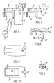
- Fig. 1 is a perspective view of an embodiment of a modular hearing aid according to the invention,
- Fig. 2 is a perspective view of a faceplate for use in the hearing aid of Fig. 1 with an inserted electronic module and a battery lid connected with the faceplate,
- Fig. 3 is a perspective view of the faceplate itself,
- Figs. 4 and 5 show details in the design of the faceplate,
- Figs. 6 and 7 are examples of an electronic module for use in the hearing aid of Fig. 1,
- Figs. 8 - 10 show the design of a battery lid connected with the faceplate, and
- Fig. 11 is an example of a hearing aid battery for use in the hearing aid of Fig. 1.
-
- The embodiment shown in Fig. 1 of a so-called ITE hearing aid for arrangement in the user's ear canal comprises a hollow plug 1 adapted to the ear canal and having a generally irregular conical shape, an
external faceplate 2 covering the outward opening of the plug 1, abattery lid 3 pivotally connected with thefaceplate 2, and anelectronic module 4 having a microphone 5, asignal processing part 6 and a sound reproducer in the form of a receiver 7. - At the narrow end, which faces the interior of the ear canal during use, the plug 1 is formed with a sound exit hole, not shown, through which sound produced by the receiver 7 can be passed on to the interior of the ear.
- When a hearing aid is adapted to a user's ear, the shape of the plug 1 is usually individually adapted to the ear canal, but the plug 1 may, however, also be manufactured as a standard component. The
faceplate 2, which is usually a standard component and may be formed as shown in Figs. 2 and 3, is then glued over the outward opening of the plug 1. After gluing, the contour of thefaceplate 2 is then formed by cutting or milling according to the contour of the edge of the orifice of the plug 1, as marked by a dashed line 2' in Fig. 2. After finishing of the plug 1 with the glued-on and contour-adaptedfaceplate 2, the other components are mounted in the hearing aid, which provides the manufacturing advantage that the plug 1 with thefaceplate 2 can be cleaned after the finishing so that the other components are not exposed to pollution during their mounting. - As shown in Figs. 1 - 3, a
recess 8 is formed in thefaceplate 2 for removable arrangement of a battery, which may be formed as shown in Fig. 11 and is inserted in thelid 3, formed as a battery holder, as well as theelectronic module 4. For this purpose, therecess 8 comprises a first region 9 for positioning of the battery and asecond region 10 coherent therewith for insertion of asocket part 11 of theelectronic module 4, which houses the microphone part 5 of the module. - To retain the
socket part 11 of theelectronic module 4, integral engaging means are formed at the edge of therecess 8, as shown in Figs. 2 and 3, and, in the embodiment shown, comprise a pair ofgrooves recess 8 in the first region 9 for positioning of the battery. Thesegrooves socket part 11 against displacement in the plane of thefaceplate 2. The engaging means further comprise a pair oftracks socket part 11 against displacement at right angles to thefaceplate 2 into the plug 1 and anotch 16 for retention of thesocket part 11 against displacement in the opposite direction. - For engagement with the engaging means formed in the
faceplate 2, thesocket part 11 of theelectronic module 4, as seen more clearly in Figs. 6 and 7, is formed with sideways projectingribs 17 for arrangement in thetracks projection 18 for engagement with thenotch 16, and with protrudingresilient lugs 19 for localization in thegrooves - When the
electronic module 4 is arranged in thefaceplate 2 with thebattery lid 3 pivoted out to the position shown in Figs. 1 and 2, the parts of the electronic module intended for arrangement in the plug 1 under thefaceplate 2, i.e., thesignal processing part 6 and the receiver 7, are passed through therecess 8 down into the plug 1. Thesocket part 11 is then placed with theribs 17 in thetracks faceplate 2 so that theprojection 18 is brought into engagement with thenotch 16, whereby theresilient lugs 19 also engage with thegrooves - The engaging means at the edges of the
recess 8 and the matching engaging means on thesocket part 11 of theelectronic module 4 may be formed so that theelectronic module 4 is passed substantially at a right angle into thesecond region 10 of therecess 8 and is then displaced in the plane of the faceplate for provision of the engagements described above. Preferably, however, thesocket part 11 is passed at an oblique angle into therecess 8 with abutment on its edge at thenotch 16, whereupon the socket part is pivoted into place and fastened by engagement of theresilient lugs 19 with thegrooves projection 18 with thenotch 16. In this design, the end of thetracks ribs 17 may be formed for abutment on each other and for retention of thesocket part 11 against displacement in the plane of thefaceplate 2 after mounting of the socket part in therecess 8. - When the
electronic module 4 is removed from the hearing aid, theresilient lugs 19 can be released from their engagement with thegrooves socket part 11 is pivoted upwards with the back edge at thenotch 16 as the pivot axis for release of theprojection 18 from its engagement with thenotch 16 so that thesocket part 11 can be removed from thefaceplate 2, and theother components 6 and 7 of theelectronic module 4 can be lifted out from the interior of the plug 1 through therecess 8. - This design, where the
socket part 11 can be pivoted in and out of its position is especially advantageous as the engaging means 12-16 of this design, apart from being formed compactly, do not require space for displacement of thesocket part 11 into the region 9 at insertion and removal. The design at the same time still provides good retention of thesocket part 11, as theresilient lugs 19 project into the region 9 for positioning of the battery and here act as levers that provide a strong fastening of the socket part and prevent its unintended pivoting out after the mounting. The relatively large distance whereby theresilient lugs 19 project into the region 9 at the same time makes it easy to remove thesocket part 11, as by intention thelugs 19 can easily be pushed out of engagement by a relatively small use of force at the outer ends of thelugs 19. - Fig. 4 shows an alternative design of the engaging means at the edge of the
recess 8, thegrooves recesses 20. Another possibility is that thegrooves groove tracks 13a which, as shown in Fig. 3, expand from the recess. This design provides good engagement of theresilient lugs 19 against unintended pivoting out of engagement. - Another alternative design of the engaging means appears from Fig. 5, where the second region 10a of the
recess 8 has a truncated wedge shape. Thetracks notch 16 are here replaced by inwardly projecting,arched ribs 21 at opposite edges of therecess 8, which retain thesocket part 11 in both directions at right angles to thefaceplate 2 by engagement with adapted grooves in thesocket part 11 instead of theribs 17. - As shown in Figs. 6 and 7, the protruding
resilient lugs 19 from thesocket part 11 may suitably be formed withintegral battery terminals 22, as after mounting of thesocket part 11 these lugs project into the first region of therecess 8, where they can be contacted by the terminals on thebattery 23 shown in Fig. 11, when it is swung into its operative position by closure of thepivotal lid 3. - In the embodiment shown, the
pivotal battery lid 3 is hinge-connected to thesocket part 11 of theelectronic module 4 by the socket part being formed withhinge bearings 24 with holders for apin 25 which can engage withhinge tracks 26 formed at one end of thebattery lid 3. - To retain the
battery 23, thebattery lid 3 has a partiallycylindrical wall 27 extending over at least 180° and defining abattery space 29 together with circular-section-shaped edge flanges 28. One terminal, usually the negative terminal on thebattery 23, is formed as apole button 30 as shown in Fig. 11, and thecylindrical wall 27 at one side of thebattery lid 3 may be formed with an uprightannular edge 31 which, at correct arrangement of the battery, encloses thepole button 30, but which, if the battery is turned the wrong way, causes thebattery lid 3 to be non-closeable. This prevents insertion of the battery with an incorrect polarization. In the embodiment shown, where thebattery lid 3 is formed withedge flanges 28 at both sides, the side of theedge flange 28 where thepole button 30 is placed is formed with adepression 32 providing room for the pole button. - When the
battery lid 3 is closed, the circular-section-shaped edge flanges 28 abut on the exterior of thefaceplate 2 around therecess 8, ensuring correct positioning of thebattery 23 at its insertion into the first region 9 of therecess 8, while at the same time thefaceplate 2 can be manufactured in a relatively simple standard design as a plane disc-shaped body without protruding abutment for the battery lid, whereby the manufacturing of the aggregate hearing aid is simplified and made cheaper, and mounting and removal of the components of the electronic module are facilitated. - As it appears particularly from Figs. 1, 2 and 8, the design of the battery lid results in retention of the
battery 23 with uncovered battery terminals formed by thepole button 30 and the end surface of the battery opposite thereto so that at closure of the battery lid, the terminals are directly brought into contact with the integral battery terminals on theresilient lugs 19 on thesocket part 11. - At the closure of the battery lid, the main part of the partially
cylindrical wall 27 will furthermore be placed up against thesocket part 11, while the remaining part of the circumferential surface of the battery is not enclosed by any socket that would take up space in the interior of the plug 1. The wall of the plug 1 can be located very close to the battery so that the plug can be formed with small dimensions. - In addition to causing accurate positioning and retention of the electronic module in relation to the
faceplate 2, the design of thesocket part 11 described above means that it supports thebattery terminals 22 of the electronic module directly, and through the hinge connection with the battery lid it causes a secure guiding of the battery during closure of the battery lid. - In the electronic module, the microphone part 5, as it appears particularly from Figs. 1, 2 and 6, is directly connected with the
socket part 11 and communicates with the surroundings throughmicrophone ports socket part 11 and thebattery lid 3, respectively, so that with a closed battery lid they correspond mutually to ensure well-defined sound access to the microphone part 5. In the embodiment shown, themicrophone port 34 in thebattery lid 3 is formed as an open slit which can relatively easily be cleaned at soiling through opening of thebattery lid 3. - The
signal processing part 6 with the amplifier circuit of the hearing aid is connected via flexible wires 35 toterminals 36 on thesocket part 11, and correspondingly, the receiver 7 is connected with thesignal processing part 6 viaflexible wires 37. This allows the most suitable arrangement of thesignal processing part 6 and the receiver 7 in the individually adapted plug 1. - The design described above of the modular hearing aid according to the invention with the individually adapted plug 1, the
faceplate 2 fastened to the plug 1 and formed according to its contour, thebattery lid 3 and its hinge connection with the socket part of theelectronic module 4 allows an extremely expedient and economic manufacturing together with a very compact design that allows manufacturing of individually adapted ITE hearing aids of reduced dimensions, which it was formerly only possible to obtain with hearing aids of a standard design, i.e., without individual adaptation of the ear canal plug.
Claims (10)
- A modular hearing aid for arrangement in a user's ear, ITE , particularly completely inside the ear canal, CIC , comprising a hollow plug (1) adapted to the ear canal and having a generally irregular conical shape and an outward opening which is covered by a faceplate (2) in which a recess (8) is formed for removable arrangement of a battery (23) as well as an electronic module (4) comprising a microphone part (5) and further parts composed of a signal processing part (6) and a sound reproducer (7), characterized in that the recess (8) comprises a first region (9) for insertion of the battery (23) and a second region (10) coherent with the first region (9) for placing of a socket part (11) of the electronic module (4), while the further parts (6, 7) thereof are placed below the faceplate (2), that at the edge of the recess (8) the faceplate (2) is formed with integral engaging means (12 - 16) for said socket part (11), and that the recess (8) is formed such that after removal of the battery (23) and the socket part (11) the first and second regions (9, 10) together allow passage also of said further parts (6, 7) for removal of the complete electronic module (4).
- A hearing aid according to claim 1, characterized in that said engaging means of the faceplate (2) comprise grooves (12, 13), tracks (14, 15) and/or notches (16) for engagement with engaging means (17 - 19) formed on said socket part (11).
- A hearing aid according to claim 2, characterized in that said engaging means on the socket part (11) comprise elastically resilient lugs (19) for engagement with said grooves (12 - 13).
- A hearing aid according to claim 3, characterized in that said lugs (19) are formed as elements which project from said socket part (11) and which, in the mounted position of the socket part (11), protrude into the first region (9) of the recess (8).
- A hearing aid according to claim 4, characterized in that said lugs (19) are integrated with battery terminals (22) projecting from said socket part (11).
- A hearing aid according to any one of the preceding claims, in which said recess (8) can be covered by a pivotal lid (3) for reception and support of said battery (23), characterized in that said lid (3) is hinge-connected with said socket part (11).
- A hearing aid according to any one of the preceding claims, characterized in that said recess (8) can be covered by a pivotal lid (3) for reception and support of said battery (23), and that the battery lid (3) is formed with a partially cylindrical wall (27) which encloses the battery (23) over at least 180° and forms a battery space (29) together with substantially circular-section-shaped edge flanges (28).
- A hearing aid according to claim 7, characterized in that at one side of the battery space (29), said partially cylindrical wall (27) is formed with an upright annular edge for enclosure of a pole button (30) on the battery (23) defining one terminal of the battery.
- A hearing aid according to claim 6, 7 or 8, characterized in that the microphone part (5) of the electronic module (4) is fastened to said socket part (11), while the signal processing part (6) and the sound reproducer (7) are interconnected and connected with said socket part (11) via flexible wire connections (35, 37).
- A hearing aid according to claim 9, characterized in that microphone ports (33, 34) are formed in the battery lid (3) and the socket part (11) and correspond mutually when the battery lid (3) is closed.
Applications Claiming Priority (3)
| Application Number | Priority Date | Filing Date | Title |
|---|---|---|---|
| DK199700421A DK42197A (en) | 1997-04-15 | 1997-04-15 | Compact modulated in-ear hearing aid |
| DK42197 | 1997-04-15 | ||
| PCT/DK1998/000148 WO1998047319A1 (en) | 1997-04-15 | 1998-04-08 | A compact modular in-the-ear hearing aid |
Publications (2)
| Publication Number | Publication Date |
|---|---|
| EP0988776A1 EP0988776A1 (en) | 2000-03-29 |
| EP0988776B1 true EP0988776B1 (en) | 2001-03-07 |
Family
ID=8093337
Family Applications (1)
| Application Number | Title | Priority Date | Filing Date |
|---|---|---|---|
| EP98914845A Expired - Lifetime EP0988776B1 (en) | 1997-04-15 | 1998-04-08 | A compact modular in-the-ear hearing aid |
Country Status (9)
| Country | Link |
|---|---|
| US (4) | US6430296B1 (en) |
| EP (1) | EP0988776B1 (en) |
| JP (1) | JP3064426B2 (en) |
| AT (1) | ATE199622T1 (en) |
| AU (1) | AU710852B2 (en) |
| CA (1) | CA2264673C (en) |
| DE (1) | DE69800577T2 (en) |
| DK (2) | DK42197A (en) |
| WO (1) | WO1998047319A1 (en) |
Cited By (4)
| Publication number | Priority date | Publication date | Assignee | Title |
|---|---|---|---|---|
| DE10214542C1 (en) * | 2002-04-02 | 2003-11-13 | Siemens Audiologische Technik | Contact device for hearing aids |
| EP1404151A1 (en) * | 2002-09-25 | 2004-03-31 | Siemens Audiologische Technik GmbH | Hearing aid to be worn in the ear with a housing |
| US7443992B2 (en) | 2004-04-15 | 2008-10-28 | Starkey Laboratories, Inc. | Method and apparatus for modular hearing aid |
| EP1169886B2 (en) † | 1999-04-13 | 2010-10-06 | Sonion Nederland B.V. | Microphone for a hearing aid |
Families Citing this family (69)
| Publication number | Priority date | Publication date | Assignee | Title |
|---|---|---|---|---|
| DK42197A (en) * | 1997-04-15 | 1998-10-16 | Toepholm & Westermann | Compact modulated in-ear hearing aid |
| EP1190601B1 (en) * | 1999-07-07 | 2003-08-27 | Auric Hörsysteme GmbH & Co. KG | Hearing-aid worn behind the ear, comprising a face plate |
| US20030089548A1 (en) * | 2000-01-19 | 2003-05-15 | Peter Frederiksen | In the ear hearing aid |
| WO2002051204A1 (en) * | 2000-12-20 | 2002-06-27 | Oticon A/S | A communication device |
| EP1246507A1 (en) | 2001-03-26 | 2002-10-02 | Widex A/S | A hearing aid with a tightening ring |
| EP1246506A1 (en) | 2001-03-26 | 2002-10-02 | Widex A/S | A CAD/CAM system for designing a hearing aid |
| EP1246505A1 (en) * | 2001-03-26 | 2002-10-02 | Widex A/S | A hearing aid with a face plate that is automatically manufactured to fit the hearing aid shell |
| DK176395B1 (en) * | 2001-04-25 | 2007-11-19 | Oticon As | ITE hearing aid and contact module for use in an ITE hearing aid. |
| US20030123687A1 (en) * | 2001-11-27 | 2003-07-03 | Gn Resound A/S | Modular hearing aid assembly |
| EP1459595B1 (en) | 2001-12-07 | 2005-05-18 | Oticon A/S | Method for producing a hearing aid |
| US7305101B2 (en) * | 2002-03-20 | 2007-12-04 | Siemens Hearing Instruments, Inc. | Instrument with an interface frame and a process for production thereof |
| DE10213847B4 (en) | 2002-03-27 | 2007-02-01 | Siemens Audiologische Technik Gmbh | Device for covering a hearing aid housing |
| CN1669355B (en) * | 2002-07-10 | 2010-06-23 | 奥迪康有限公司 | Hearing aid or similar audio device and method for producing a hearing aid |
| US7171014B2 (en) * | 2002-10-31 | 2007-01-30 | Starkey Laboratories, Inc. | Hearing aid battery door seal |
| US7142682B2 (en) | 2002-12-20 | 2006-11-28 | Sonion Mems A/S | Silicon-based transducer for use in hearing instruments and listening devices |
| DK1473970T3 (en) * | 2003-05-01 | 2008-09-29 | Sonion Roskilde As | Miniature hearing aid insert module |
| DK1414270T3 (en) * | 2003-11-21 | 2006-11-13 | Phonak Ag | Housing for hearing aid equipment respectively. a hearing aid |
| US20050157898A1 (en) * | 2004-01-16 | 2005-07-21 | Bruno Gabathuler | Housing for a hearing device |
| DK2285138T3 (en) * | 2004-02-19 | 2013-07-01 | Oticon As | Hearing aid with antenna for receiving and transmitting electromagnetic signals |
| CN1939091A (en) * | 2004-03-31 | 2007-03-28 | 唯听助听器公司 | Component for a hearing aid and a hearing aid |
| US20050259839A1 (en) * | 2004-05-19 | 2005-11-24 | Phonak Ag | Construction for hearing devices or hearing aids |
| EP1626612A3 (en) | 2004-08-11 | 2009-05-06 | Sonion Nederland B.V. | Hearing aid microphone mounting structure and method for mounting |
| DK1829419T3 (en) * | 2004-12-22 | 2012-04-02 | Widex As | BTE hearing aid with individually tailored shell and earplug |
| EP1715722A2 (en) * | 2005-04-21 | 2006-10-25 | Sonion Roskilde A/S | A mounting frame for custom hearing aid instruments |
| US8108999B2 (en) * | 2006-02-02 | 2012-02-07 | Widex A/S | Method of assembling a hearing aid |
| EP1838134B1 (en) * | 2006-03-23 | 2014-06-11 | Oticon A/S | In the ear audio device and method for fastening an electronic module in a cavity in a custom made shell part for an in the ear audio device |
| US20080230495A1 (en) * | 2007-03-19 | 2008-09-25 | Siemens Hearing Instruments Inc. | Secure Mount For A Hearing Instrument Electronics Module |
| US8180084B2 (en) * | 2007-03-21 | 2012-05-15 | Starkey Laboratories, Inc. | Integrated battery door and switch |
| US20110022032A1 (en) * | 2007-10-05 | 2011-01-27 | Tyco Healthcare Group Lp | Battery ejection design for a surgical device |
| WO2009076523A1 (en) | 2007-12-11 | 2009-06-18 | Andrea Electronics Corporation | Adaptive filtering in a sensor array system |
| US9392360B2 (en) | 2007-12-11 | 2016-07-12 | Andrea Electronics Corporation | Steerable sensor array system with video input |
| US8542843B2 (en) * | 2008-04-25 | 2013-09-24 | Andrea Electronics Corporation | Headset with integrated stereo array microphone |
| US8831259B2 (en) * | 2008-09-18 | 2014-09-09 | Siemens Medical Instruments Pte. Ltd. | Hearing aid faceplate arrangement |
| JP5221307B2 (en) * | 2008-12-03 | 2013-06-26 | リオン株式会社 | Ear hole type hearing aid |
| DE102009009286B4 (en) * | 2009-02-17 | 2013-08-08 | Siemens Medical Instruments Pte. Ltd. | Hearing device with individually oriented electronic component and manufacturing process |
| WO2011031881A2 (en) * | 2009-09-10 | 2011-03-17 | iHear Medical, Inc. | Canal hearing device with disposable battery module |
| DE102010014316A1 (en) * | 2010-04-09 | 2011-10-13 | Siemens Medical Instruments Pte. Ltd. | Hearing aid with audio shoe |
| DE102010022323A1 (en) * | 2010-06-01 | 2011-12-01 | Siemens Medical Instruments Pte. Ltd. | Deep-ear-canal hearing instrument |
| WO2012112148A1 (en) | 2011-02-16 | 2012-08-23 | Siemens Hearing Instruments, Inc. | Amplifier module for a hearing instrument |
| US8855345B2 (en) | 2012-03-19 | 2014-10-07 | iHear Medical, Inc. | Battery module for perpendicular docking into a canal hearing device |
| US8798301B2 (en) | 2012-05-01 | 2014-08-05 | iHear Medical, Inc. | Tool for removal of canal hearing device from ear canal |
| US9002046B2 (en) | 2012-06-29 | 2015-04-07 | iHear Medical, Inc. | Method and system for transcutaneous proximity wireless control of a canal hearing device |
| US9185504B2 (en) | 2012-11-30 | 2015-11-10 | iHear Medical, Inc. | Dynamic pressure vent for canal hearing devices |
| US8867768B2 (en) | 2012-11-30 | 2014-10-21 | iHear Medical, Inc. | Earpiece assembly with foil clip |
| US9078075B2 (en) | 2012-11-30 | 2015-07-07 | iHear Medical, Inc. | Tool for insertion of canal hearing device into the ear canal |
| DK2936831T3 (en) * | 2012-12-19 | 2019-07-22 | Widex As | HEARING WITH A Biased BATTERY SPRING |
| US9060233B2 (en) | 2013-03-06 | 2015-06-16 | iHear Medical, Inc. | Rechargeable canal hearing device and systems |
| US9088852B2 (en) | 2013-03-06 | 2015-07-21 | iHear Medical, Inc. | Disengagement tool for a modular canal hearing device and systems including same |
| US9107016B2 (en) | 2013-07-16 | 2015-08-11 | iHear Medical, Inc. | Interactive hearing aid fitting system and methods |
| US9439008B2 (en) | 2013-07-16 | 2016-09-06 | iHear Medical, Inc. | Online hearing aid fitting system and methods for non-expert user |
| US9031247B2 (en) | 2013-07-16 | 2015-05-12 | iHear Medical, Inc. | Hearing aid fitting systems and methods using sound segments representing relevant soundscape |
| US9326706B2 (en) | 2013-07-16 | 2016-05-03 | iHear Medical, Inc. | Hearing profile test system and method |
| DE102014202940A1 (en) * | 2014-02-18 | 2014-12-24 | Siemens Medical Instruments Pte. Ltd. | Battery contact with integrated bearing element |
| US9805590B2 (en) | 2014-08-15 | 2017-10-31 | iHear Medical, Inc. | Hearing device and methods for wireless remote control of an appliance |
| US9769577B2 (en) | 2014-08-22 | 2017-09-19 | iHear Medical, Inc. | Hearing device and methods for wireless remote control of an appliance |
| US9807524B2 (en) | 2014-08-30 | 2017-10-31 | iHear Medical, Inc. | Trenched sealing retainer for canal hearing device |
| US20160066822A1 (en) | 2014-09-08 | 2016-03-10 | iHear Medical, Inc. | Hearing test system for non-expert user with built-in calibration and method |
| WO2016044178A1 (en) | 2014-09-15 | 2016-03-24 | iHear Medical, Inc. | Canal hearing device with elongate frequency shaping sound channel |
| US10097933B2 (en) | 2014-10-06 | 2018-10-09 | iHear Medical, Inc. | Subscription-controlled charging of a hearing device |
| US20160134742A1 (en) | 2014-11-11 | 2016-05-12 | iHear Medical, Inc. | Subscription-based wireless service for a canal hearing device |
| US10085678B2 (en) | 2014-12-16 | 2018-10-02 | iHear Medical, Inc. | System and method for determining WHO grading of hearing impairment |
| US10045128B2 (en) | 2015-01-07 | 2018-08-07 | iHear Medical, Inc. | Hearing device test system for non-expert user at home and non-clinical settings |
| US10489833B2 (en) | 2015-05-29 | 2019-11-26 | iHear Medical, Inc. | Remote verification of hearing device for e-commerce transaction |
| DK3128578T3 (en) * | 2015-08-07 | 2018-09-10 | Oticon As | BATTERY DEVICE FOR A HEARING |
| WO2017096279A1 (en) | 2015-12-04 | 2017-06-08 | iHear Medical, Inc. | Self-fitting of a hearing device |
| WO2018153456A1 (en) | 2017-02-23 | 2018-08-30 | Sonova Ag | A module of a hearing device, a removal tool, a hearing device and a method of separating a module from a housing |
| US11240614B2 (en) | 2017-02-23 | 2022-02-01 | Sonova Ag | Method of sealing a module and a hearing device |
| USD864164S1 (en) * | 2018-03-14 | 2019-10-22 | Dadong Liu | Earphone |
| DE102021205471B3 (en) * | 2021-05-28 | 2022-11-10 | Sivantos Pte. Ltd. | hearing device |
Family Cites Families (17)
| Publication number | Priority date | Publication date | Assignee | Title |
|---|---|---|---|---|
| DE9415594U1 (en) * | 1994-09-29 | 1996-02-08 | Toepholm & Westermann | Hearing aid |
| CH68311A (en) | 1914-05-22 | 1915-03-01 | Otto Steinmann | Innovation in braiding machines |
| AT372812B (en) | 1982-04-07 | 1983-11-25 | Viennatone Gmbh | IN THE EAR HOERGERAET |
| DE8318579U1 (en) * | 1983-06-27 | 1983-11-17 | Siemens AG, 1000 Berlin und 8000 München | Hearing aid |
| US4598177A (en) * | 1985-01-16 | 1986-07-01 | Sears, Roebuck, & Co. | Hearing aid with self-contained battery compartment and volume control |
| DE8518681U1 (en) * | 1985-06-27 | 1986-06-12 | Siemens AG, 1000 Berlin und 8000 München | Hearing aid |
| US4716985A (en) * | 1986-05-16 | 1988-01-05 | Siemens Aktiengesellschaft | In-the-ear hearing aid |
| US4870688A (en) * | 1986-05-27 | 1989-09-26 | Barry Voroba | Mass production auditory canal hearing aid |
| US5201008A (en) | 1987-01-27 | 1993-04-06 | Unitron Industries Ltd. | Modular hearing aid with lid hinged to faceplate |
| EP0311233A3 (en) * | 1987-10-05 | 1990-06-06 | Richards Medical Company | Touch contacts for hearing aid volume control |
| US5347584A (en) * | 1991-05-31 | 1994-09-13 | Rion Kabushiki-Kaisha | Hearing aid |
| DE4121311C1 (en) * | 1991-06-27 | 1992-08-13 | Siemens Ag, 8000 Muenchen, De | |
| DE4121312C1 (en) * | 1991-06-27 | 1992-05-14 | Siemens Ag, 8000 Muenchen, De | |
| DE4444586C1 (en) * | 1994-12-14 | 1996-02-22 | Siemens Audiologische Technik | Programmable hearing aid with programming adaptor |
| DE19636800A1 (en) * | 1996-09-11 | 1998-03-12 | Audio Service Gmbh As | In-ear hearing aid |
| DE19706306C1 (en) * | 1997-02-18 | 1998-10-08 | Siemens Audiologische Technik | In-ear hearing aid |
| DK42197A (en) * | 1997-04-15 | 1998-10-16 | Toepholm & Westermann | Compact modulated in-ear hearing aid |
-
1997
- 1997-04-15 DK DK199700421A patent/DK42197A/en not_active Application Discontinuation
-
1998
- 1998-04-08 DK DK98914845T patent/DK0988776T3/en active
- 1998-04-08 WO PCT/DK1998/000148 patent/WO1998047319A1/en active IP Right Grant
- 1998-04-08 CA CA002264673A patent/CA2264673C/en not_active Expired - Fee Related
- 1998-04-08 US US09/254,260 patent/US6430296B1/en not_active Expired - Lifetime
- 1998-04-08 JP JP10543384A patent/JP3064426B2/en not_active Expired - Fee Related
- 1998-04-08 AU AU69190/98A patent/AU710852B2/en not_active Ceased
- 1998-04-08 EP EP98914845A patent/EP0988776B1/en not_active Expired - Lifetime
- 1998-04-08 DE DE69800577T patent/DE69800577T2/en not_active Expired - Lifetime
- 1998-04-08 AT AT98914845T patent/ATE199622T1/en not_active IP Right Cessation
-
2002
- 2002-08-02 US US10/209,940 patent/US6678385B2/en not_active Expired - Lifetime
-
2003
- 2003-11-25 US US10/720,093 patent/US7024012B2/en not_active Expired - Fee Related
-
2006
- 2006-01-19 US US11/275,618 patent/US7321663B2/en not_active Expired - Fee Related
Cited By (5)
| Publication number | Priority date | Publication date | Assignee | Title |
|---|---|---|---|---|
| EP1169886B2 (en) † | 1999-04-13 | 2010-10-06 | Sonion Nederland B.V. | Microphone for a hearing aid |
| DE10214542C1 (en) * | 2002-04-02 | 2003-11-13 | Siemens Audiologische Technik | Contact device for hearing aids |
| EP1404151A1 (en) * | 2002-09-25 | 2004-03-31 | Siemens Audiologische Technik GmbH | Hearing aid to be worn in the ear with a housing |
| US7191867B2 (en) | 2002-09-25 | 2007-03-20 | Siemens Audiologische Technik Gmbh | Hearing aid device that can be worn in the ear with a housing |
| US7443992B2 (en) | 2004-04-15 | 2008-10-28 | Starkey Laboratories, Inc. | Method and apparatus for modular hearing aid |
Also Published As
| Publication number | Publication date |
|---|---|
| AU710852B2 (en) | 1999-09-30 |
| US7321663B2 (en) | 2008-01-22 |
| CA2264673C (en) | 2004-12-14 |
| ATE199622T1 (en) | 2001-03-15 |
| DE69800577T2 (en) | 2001-08-23 |
| DE69800577D1 (en) | 2001-04-12 |
| US6678385B2 (en) | 2004-01-13 |
| JP3064426B2 (en) | 2000-07-12 |
| US20030059074A1 (en) | 2003-03-27 |
| CA2264673A1 (en) | 1998-10-22 |
| US6430296B1 (en) | 2002-08-06 |
| JP2000503197A (en) | 2000-03-14 |
| EP0988776A1 (en) | 2000-03-29 |
| DK0988776T3 (en) | 2001-04-17 |
| WO1998047319A1 (en) | 1998-10-22 |
| US7024012B2 (en) | 2006-04-04 |
| US20060104466A1 (en) | 2006-05-18 |
| DK42197A (en) | 1998-10-16 |
| US20040105561A1 (en) | 2004-06-03 |
| AU6919098A (en) | 1998-11-11 |
Similar Documents
| Publication | Publication Date | Title |
|---|---|---|
| EP0988776B1 (en) | A compact modular in-the-ear hearing aid | |
| EP0263667B1 (en) | Modular hearing aid with lid hinged to faceplate | |
| US5201008A (en) | Modular hearing aid with lid hinged to faceplate | |
| CA1236208A (en) | Hearing aid | |
| US7068804B2 (en) | Communication system with communication element attachable to pivoting battery compartment | |
| JPH0246160Y2 (en) | ||
| US8213651B2 (en) | Hearing device with a contact unit and an associated external unit | |
| WO2000021334A2 (en) | Behind-the-ear hearing aid | |
| WO2006067133A1 (en) | Behind-the-ear hearing aid | |
| US20070036372A1 (en) | Hearing device with battery door | |
| EP1346603B1 (en) | A communication device | |
| EP1483938B1 (en) | Microphone and battery configuration for hearing instruments | |
| CA2458323C (en) | A compact modular in-the-ear hearing aid | |
| US6678386B2 (en) | Programmable module | |
| US6959097B1 (en) | Behind the ear hearing aid with front plate | |
| CA2201356A1 (en) | A camera and accessory | |
| US20200267484A1 (en) | Open fit canal hearing device | |
| EP1599069A1 (en) | Hearing device with battery door | |
| JP2994929B2 (en) | Ear-hearing hearing aid | |
| CN112770304B (en) | Pairing method, wireless adapter and wireless earphone | |
| JP2584873Y2 (en) | Electrode connection device | |
| JP2005286851A (en) | Electronic device | |
| KR200189217Y1 (en) | Mp-3 player | |
| JP2010011321A (en) | Ear hole type hearing aid | |
| JPH07222292A (en) | Battery housing device |
Legal Events
| Date | Code | Title | Description |
|---|---|---|---|
| PUAI | Public reference made under article 153(3) epc to a published international application that has entered the european phase |
Free format text: ORIGINAL CODE: 0009012 |
|
| 17P | Request for examination filed |
Effective date: 19990225 |
|
| AK | Designated contracting states |
Kind code of ref document: A1 Designated state(s): AT CH DE DK FR GB IT LI NL |
|
| GRAG | Despatch of communication of intention to grant |
Free format text: ORIGINAL CODE: EPIDOS AGRA |
|
| GRAG | Despatch of communication of intention to grant |
Free format text: ORIGINAL CODE: EPIDOS AGRA |
|
| GRAH | Despatch of communication of intention to grant a patent |
Free format text: ORIGINAL CODE: EPIDOS IGRA |
|
| EL | Fr: translation of claims filed | ||
| 17Q | First examination report despatched |
Effective date: 20001123 |
|
| GRAH | Despatch of communication of intention to grant a patent |
Free format text: ORIGINAL CODE: EPIDOS IGRA |
|
| TCAT | At: translation of patent claims filed | ||
| GRAA | (expected) grant |
Free format text: ORIGINAL CODE: 0009210 |
|
| TCNL | Nl: translation of patent claims filed | ||
| AK | Designated contracting states |
Kind code of ref document: B1 Designated state(s): AT CH DE DK FR GB IT LI NL |
|
| REF | Corresponds to: |
Ref document number: 199622 Country of ref document: AT Date of ref document: 20010315 Kind code of ref document: T |
|
| ITF | It: translation for a ep patent filed |
Owner name: SOCIETA' ITALIANA BREVETTI S.P.A. |
|
| REG | Reference to a national code |
Ref country code: CH Ref legal event code: EP |
|
| REF | Corresponds to: |
Ref document number: 69800577 Country of ref document: DE Date of ref document: 20010412 |
|
| ET | Fr: translation filed | ||
| REG | Reference to a national code |
Ref country code: DK Ref legal event code: T3 |
|
| REG | Reference to a national code |
Ref country code: CH Ref legal event code: NV Representative=s name: PATENTANWAELTE SCHAAD, BALASS, MENZL & PARTNER AG |
|
| PLBQ | Unpublished change to opponent data |
Free format text: ORIGINAL CODE: EPIDOS OPPO |
|
| PLBI | Opposition filed |
Free format text: ORIGINAL CODE: 0009260 |
|
| 26 | Opposition filed |
Opponent name: TUERK + TUERK ELECTRONIC GMBH Effective date: 20011013 |
|
| REG | Reference to a national code |
Ref country code: GB Ref legal event code: IF02 |
|
| PLBF | Reply of patent proprietor to notice(s) of opposition |
Free format text: ORIGINAL CODE: EPIDOS OBSO |
|
| NLR1 | Nl: opposition has been filed with the epo |
Opponent name: TUERK ELECTRONIC GMBH |
|
| RAP2 | Party data changed (patent owner data changed or rights of a patent transferred) |
Owner name: WIDEX A/S |
|
| PLBF | Reply of patent proprietor to notice(s) of opposition |
Free format text: ORIGINAL CODE: EPIDOS OBSO |
|
| NLT2 | Nl: modifications (of names), taken from the european patent patent bulletin |
Owner name: WIDEX A/S |
|
| PLBF | Reply of patent proprietor to notice(s) of opposition |
Free format text: ORIGINAL CODE: EPIDOS OBSO |
|
| PLBP | Opposition withdrawn |
Free format text: ORIGINAL CODE: 0009264 |
|
| PLBD | Termination of opposition procedure: decision despatched |
Free format text: ORIGINAL CODE: EPIDOSNOPC1 |
|
| PLBM | Termination of opposition procedure: date of legal effect published |
Free format text: ORIGINAL CODE: 0009276 |
|
| STAA | Information on the status of an ep patent application or granted ep patent |
Free format text: STATUS: OPPOSITION PROCEDURE CLOSED |
|
| 27C | Opposition proceedings terminated |
Effective date: 20040704 |
|
| NLR2 | Nl: decision of opposition |
Effective date: 20040704 |
|
| PGFP | Annual fee paid to national office [announced via postgrant information from national office to epo] |
Ref country code: AT Payment date: 20060412 Year of fee payment: 9 |
|
| PG25 | Lapsed in a contracting state [announced via postgrant information from national office to epo] |
Ref country code: AT Free format text: LAPSE BECAUSE OF NON-PAYMENT OF DUE FEES Effective date: 20070408 |
|
| PLAB | Opposition data, opponent's data or that of the opponent's representative modified |
Free format text: ORIGINAL CODE: 0009299OPPO |
|
| REG | Reference to a national code |
Ref country code: DE Ref legal event code: R082 Ref document number: 69800577 Country of ref document: DE Representative=s name: BETTEN & RESCH PATENT- UND RECHTSANWAELTE PART, DE Effective date: 20111229 Ref country code: DE Ref legal event code: R082 Ref document number: 69800577 Country of ref document: DE Representative=s name: PATENTANWAELTE BETTEN & RESCH, DE Effective date: 20111229 Ref country code: DE Ref legal event code: R081 Ref document number: 69800577 Country of ref document: DE Owner name: WIDEX A/S, DK Free format text: FORMER OWNER: WIDEX A/S, VAERLOESE, DK Effective date: 20111229 |
|
| PGFP | Annual fee paid to national office [announced via postgrant information from national office to epo] |
Ref country code: NL Payment date: 20120413 Year of fee payment: 15 |
|
| PGFP | Annual fee paid to national office [announced via postgrant information from national office to epo] |
Ref country code: GB Payment date: 20120404 Year of fee payment: 15 Ref country code: FR Payment date: 20120504 Year of fee payment: 15 |
|
| PGFP | Annual fee paid to national office [announced via postgrant information from national office to epo] |
Ref country code: IT Payment date: 20120419 Year of fee payment: 15 |
|
| REG | Reference to a national code |
Ref country code: NL Ref legal event code: V1 Effective date: 20131101 |
|
| GBPC | Gb: european patent ceased through non-payment of renewal fee |
Effective date: 20130408 |
|
| PG25 | Lapsed in a contracting state [announced via postgrant information from national office to epo] |
Ref country code: GB Free format text: LAPSE BECAUSE OF NON-PAYMENT OF DUE FEES Effective date: 20130408 |
|
| REG | Reference to a national code |
Ref country code: FR Ref legal event code: ST Effective date: 20131231 |
|
| PG25 | Lapsed in a contracting state [announced via postgrant information from national office to epo] |
Ref country code: FR Free format text: LAPSE BECAUSE OF NON-PAYMENT OF DUE FEES Effective date: 20130430 Ref country code: NL Free format text: LAPSE BECAUSE OF NON-PAYMENT OF DUE FEES Effective date: 20131101 Ref country code: IT Free format text: LAPSE BECAUSE OF NON-PAYMENT OF DUE FEES Effective date: 20130408 |
|
| PGFP | Annual fee paid to national office [announced via postgrant information from national office to epo] |
Ref country code: DK Payment date: 20150410 Year of fee payment: 18 Ref country code: DE Payment date: 20150331 Year of fee payment: 18 Ref country code: CH Payment date: 20150414 Year of fee payment: 18 |
|
| REG | Reference to a national code |
Ref country code: DE Ref legal event code: R119 Ref document number: 69800577 Country of ref document: DE |
|
| REG | Reference to a national code |
Ref country code: DK Ref legal event code: EBP Effective date: 20160430 |
|
| REG | Reference to a national code |
Ref country code: CH Ref legal event code: PL |
|
| PG25 | Lapsed in a contracting state [announced via postgrant information from national office to epo] |
Ref country code: CH Free format text: LAPSE BECAUSE OF NON-PAYMENT OF DUE FEES Effective date: 20160430 Ref country code: DE Free format text: LAPSE BECAUSE OF NON-PAYMENT OF DUE FEES Effective date: 20161101 Ref country code: LI Free format text: LAPSE BECAUSE OF NON-PAYMENT OF DUE FEES Effective date: 20160430 |
|
| PG25 | Lapsed in a contracting state [announced via postgrant information from national office to epo] |
Ref country code: DK Free format text: LAPSE BECAUSE OF NON-PAYMENT OF DUE FEES Effective date: 20160430 |