EP0988570B1 - Multiple alignment connector ferrule - Google Patents
Multiple alignment connector ferrule Download PDFInfo
- Publication number
- EP0988570B1 EP0988570B1 EP97913678A EP97913678A EP0988570B1 EP 0988570 B1 EP0988570 B1 EP 0988570B1 EP 97913678 A EP97913678 A EP 97913678A EP 97913678 A EP97913678 A EP 97913678A EP 0988570 B1 EP0988570 B1 EP 0988570B1
- Authority
- EP
- European Patent Office
- Prior art keywords
- alignment
- ferrule
- ball
- connector ferrule
- connector
- Prior art date
- Legal status (The legal status is an assumption and is not a legal conclusion. Google has not performed a legal analysis and makes no representation as to the accuracy of the status listed.)
- Expired - Lifetime
Links
- 239000013307 optical fiber Substances 0.000 claims description 25
- 239000000835 fiber Substances 0.000 claims description 19
- 230000003287 optical effect Effects 0.000 claims description 14
- 239000004033 plastic Substances 0.000 claims description 4
- 229920003023 plastic Polymers 0.000 claims description 4
- 230000000717 retained effect Effects 0.000 claims description 3
- 238000000034 method Methods 0.000 description 11
- 238000004519 manufacturing process Methods 0.000 description 7
- 239000000919 ceramic Substances 0.000 description 5
- 239000000463 material Substances 0.000 description 4
- 230000007704 transition Effects 0.000 description 3
- 229910000831 Steel Inorganic materials 0.000 description 2
- 239000000853 adhesive Substances 0.000 description 2
- 230000001070 adhesive effect Effects 0.000 description 2
- 230000008901 benefit Effects 0.000 description 2
- 230000005540 biological transmission Effects 0.000 description 2
- 238000009434 installation Methods 0.000 description 2
- 238000005498 polishing Methods 0.000 description 2
- 238000000926 separation method Methods 0.000 description 2
- 230000008054 signal transmission Effects 0.000 description 2
- 239000010959 steel Substances 0.000 description 2
- 238000012546 transfer Methods 0.000 description 2
- 239000004593 Epoxy Substances 0.000 description 1
- 229920000106 Liquid crystal polymer Polymers 0.000 description 1
- 239000004977 Liquid-crystal polymers (LCPs) Substances 0.000 description 1
- 238000003491 array Methods 0.000 description 1
- 230000000712 assembly Effects 0.000 description 1
- 238000000429 assembly Methods 0.000 description 1
- 238000004891 communication Methods 0.000 description 1
- 238000011161 development Methods 0.000 description 1
- 230000000694 effects Effects 0.000 description 1
- 229920003247 engineering thermoplastic Polymers 0.000 description 1
- 239000011521 glass Substances 0.000 description 1
- 239000003365 glass fiber Substances 0.000 description 1
- 238000001746 injection moulding Methods 0.000 description 1
- 239000002184 metal Substances 0.000 description 1
- 230000007935 neutral effect Effects 0.000 description 1
- 230000005693 optoelectronics Effects 0.000 description 1
- 238000012545 processing Methods 0.000 description 1
Images
Classifications
-
- G—PHYSICS
- G02—OPTICS
- G02B—OPTICAL ELEMENTS, SYSTEMS OR APPARATUS
- G02B6/00—Light guides; Structural details of arrangements comprising light guides and other optical elements, e.g. couplings
- G02B6/24—Coupling light guides
- G02B6/36—Mechanical coupling means
- G02B6/38—Mechanical coupling means having fibre to fibre mating means
- G02B6/3801—Permanent connections, i.e. wherein fibres are kept aligned by mechanical means
- G02B6/3803—Adjustment or alignment devices for alignment prior to splicing
-
- G—PHYSICS
- G02—OPTICS
- G02B—OPTICAL ELEMENTS, SYSTEMS OR APPARATUS
- G02B6/00—Light guides; Structural details of arrangements comprising light guides and other optical elements, e.g. couplings
- G02B6/24—Coupling light guides
- G02B6/36—Mechanical coupling means
- G02B6/38—Mechanical coupling means having fibre to fibre mating means
- G02B6/3807—Dismountable connectors, i.e. comprising plugs
- G02B6/3833—Details of mounting fibres in ferrules; Assembly methods; Manufacture
- G02B6/3834—Means for centering or aligning the light guide within the ferrule
- G02B6/3838—Means for centering or aligning the light guide within the ferrule using grooves for light guides
- G02B6/3839—Means for centering or aligning the light guide within the ferrule using grooves for light guides for a plurality of light guides
-
- G—PHYSICS
- G02—OPTICS
- G02B—OPTICAL ELEMENTS, SYSTEMS OR APPARATUS
- G02B6/00—Light guides; Structural details of arrangements comprising light guides and other optical elements, e.g. couplings
- G02B6/24—Coupling light guides
- G02B6/36—Mechanical coupling means
- G02B6/38—Mechanical coupling means having fibre to fibre mating means
- G02B6/3807—Dismountable connectors, i.e. comprising plugs
- G02B6/3869—Mounting ferrules to connector body, i.e. plugs
-
- G—PHYSICS
- G02—OPTICS
- G02B—OPTICAL ELEMENTS, SYSTEMS OR APPARATUS
- G02B6/00—Light guides; Structural details of arrangements comprising light guides and other optical elements, e.g. couplings
- G02B6/24—Coupling light guides
- G02B6/36—Mechanical coupling means
- G02B6/38—Mechanical coupling means having fibre to fibre mating means
- G02B6/3807—Dismountable connectors, i.e. comprising plugs
- G02B6/3887—Anchoring optical cables to connector housings, e.g. strain relief features
- G02B6/3888—Protection from over-extension or over-compression
-
- G—PHYSICS
- G02—OPTICS
- G02B—OPTICAL ELEMENTS, SYSTEMS OR APPARATUS
- G02B6/00—Light guides; Structural details of arrangements comprising light guides and other optical elements, e.g. couplings
- G02B6/24—Coupling light guides
- G02B6/36—Mechanical coupling means
- G02B6/38—Mechanical coupling means having fibre to fibre mating means
- G02B6/3807—Dismountable connectors, i.e. comprising plugs
- G02B6/389—Dismountable connectors, i.e. comprising plugs characterised by the method of fastening connecting plugs and sockets, e.g. screw- or nut-lock, snap-in, bayonet type
- G02B6/3893—Push-pull type, e.g. snap-in, push-on
-
- G—PHYSICS
- G02—OPTICS
- G02B—OPTICAL ELEMENTS, SYSTEMS OR APPARATUS
- G02B6/00—Light guides; Structural details of arrangements comprising light guides and other optical elements, e.g. couplings
- G02B6/24—Coupling light guides
- G02B6/36—Mechanical coupling means
- G02B6/3628—Mechanical coupling means for mounting fibres to supporting carriers
- G02B6/3632—Mechanical coupling means for mounting fibres to supporting carriers characterised by the cross-sectional shape of the mechanical coupling means
- G02B6/3636—Mechanical coupling means for mounting fibres to supporting carriers characterised by the cross-sectional shape of the mechanical coupling means the mechanical coupling means being grooves
-
- G—PHYSICS
- G02—OPTICS
- G02B—OPTICAL ELEMENTS, SYSTEMS OR APPARATUS
- G02B6/00—Light guides; Structural details of arrangements comprising light guides and other optical elements, e.g. couplings
- G02B6/24—Coupling light guides
- G02B6/36—Mechanical coupling means
- G02B6/38—Mechanical coupling means having fibre to fibre mating means
- G02B6/3801—Permanent connections, i.e. wherein fibres are kept aligned by mechanical means
- G02B6/3806—Semi-permanent connections, i.e. wherein the mechanical means keeping the fibres aligned allow for removal of the fibres
-
- G—PHYSICS
- G02—OPTICS
- G02B—OPTICAL ELEMENTS, SYSTEMS OR APPARATUS
- G02B6/00—Light guides; Structural details of arrangements comprising light guides and other optical elements, e.g. couplings
- G02B6/24—Coupling light guides
- G02B6/36—Mechanical coupling means
- G02B6/38—Mechanical coupling means having fibre to fibre mating means
- G02B6/3807—Dismountable connectors, i.e. comprising plugs
- G02B6/381—Dismountable connectors, i.e. comprising plugs of the ferrule type, e.g. fibre ends embedded in ferrules, connecting a pair of fibres
- G02B6/3818—Dismountable connectors, i.e. comprising plugs of the ferrule type, e.g. fibre ends embedded in ferrules, connecting a pair of fibres of a low-reflection-loss type
- G02B6/3821—Dismountable connectors, i.e. comprising plugs of the ferrule type, e.g. fibre ends embedded in ferrules, connecting a pair of fibres of a low-reflection-loss type with axial spring biasing or loading means
-
- G—PHYSICS
- G02—OPTICS
- G02B—OPTICAL ELEMENTS, SYSTEMS OR APPARATUS
- G02B6/00—Light guides; Structural details of arrangements comprising light guides and other optical elements, e.g. couplings
- G02B6/24—Coupling light guides
- G02B6/36—Mechanical coupling means
- G02B6/38—Mechanical coupling means having fibre to fibre mating means
- G02B6/3807—Dismountable connectors, i.e. comprising plugs
- G02B6/381—Dismountable connectors, i.e. comprising plugs of the ferrule type, e.g. fibre ends embedded in ferrules, connecting a pair of fibres
- G02B6/3825—Dismountable connectors, i.e. comprising plugs of the ferrule type, e.g. fibre ends embedded in ferrules, connecting a pair of fibres with an intermediate part, e.g. adapter, receptacle, linking two plugs
-
- G—PHYSICS
- G02—OPTICS
- G02B—OPTICAL ELEMENTS, SYSTEMS OR APPARATUS
- G02B6/00—Light guides; Structural details of arrangements comprising light guides and other optical elements, e.g. couplings
- G02B6/24—Coupling light guides
- G02B6/36—Mechanical coupling means
- G02B6/38—Mechanical coupling means having fibre to fibre mating means
- G02B6/3807—Dismountable connectors, i.e. comprising plugs
- G02B6/3833—Details of mounting fibres in ferrules; Assembly methods; Manufacture
- G02B6/3855—Details of mounting fibres in ferrules; Assembly methods; Manufacture characterised by the method of anchoring or fixing the fibre within the ferrule
- G02B6/3861—Adhesive bonding
-
- G—PHYSICS
- G02—OPTICS
- G02B—OPTICAL ELEMENTS, SYSTEMS OR APPARATUS
- G02B6/00—Light guides; Structural details of arrangements comprising light guides and other optical elements, e.g. couplings
- G02B6/24—Coupling light guides
- G02B6/36—Mechanical coupling means
- G02B6/38—Mechanical coupling means having fibre to fibre mating means
- G02B6/3807—Dismountable connectors, i.e. comprising plugs
- G02B6/3873—Connectors using guide surfaces for aligning ferrule ends, e.g. tubes, sleeves, V-grooves, rods, pins, balls
- G02B6/3882—Connectors using guide surfaces for aligning ferrule ends, e.g. tubes, sleeves, V-grooves, rods, pins, balls using rods, pins or balls to align a pair of ferrule ends
-
- G—PHYSICS
- G02—OPTICS
- G02B—OPTICAL ELEMENTS, SYSTEMS OR APPARATUS
- G02B6/00—Light guides; Structural details of arrangements comprising light guides and other optical elements, e.g. couplings
- G02B6/24—Coupling light guides
- G02B6/36—Mechanical coupling means
- G02B6/38—Mechanical coupling means having fibre to fibre mating means
- G02B6/3807—Dismountable connectors, i.e. comprising plugs
- G02B6/3873—Connectors using guide surfaces for aligning ferrule ends, e.g. tubes, sleeves, V-grooves, rods, pins, balls
- G02B6/3885—Multicore or multichannel optical connectors, i.e. one single ferrule containing more than one fibre, e.g. ribbon type
Definitions
- the present invention relates generally to connectors for optical fibers.
- the present invention relates to a multiple alignment connector ferrule for an optical fiber cable connector.
- Optical fiber ribbon cables are well known for the transmission of optical signals.
- Use of optical cables, including optical fiber ribbon cables, has generally been limited to long haul trunking installations where the improved transmission characteristics of the optical fibers justify the greater expense in typical difficulty associated with their manufacturing and installation.
- the advantages of using optical cable for transmission of signals across shorter distances or, for interconnecting local devices continues to grow. With this growth has come a need to connect fiber optic ribbon cables to a multiplicity of devices.
- optical cable connectors have been developed to aid in the connection of fiber optic ribbon cables.
- Examples of known multi-fiber connectors include the MACTM connector by Berg Electronics and the MTTM Connector by U.S. Conec. Further examples of optical connectors are illustrated in U.S. -A-5,420,952; US-A-5,276,755 US-A-5,500,915; US-A-4,784,457; US-A-5,430,819; and US-A 5,287,426.
- optical fiber connector ferrules which are provided with alignment pins or balls.
- the present invention is an optical fiber connector ferrule that satisfies the existing need for providing an easy to manufacture, inexpensive optical connector having multiple alignment methods.
- the present invention is an optical fiber connector ferrule having a fiber engaging and alignment surface for engaging and aligning at least one optical fiber.
- the ferrule also has a connector engagement surface.
- the connector ferrule of the present invention is preferably made of standard engineering thermoplastics.
- the connector ferrule of the present invention has the capability of providing multiple alignment methods for providing compatibility with many different connector devices.
- the multiple alignment methods include ball and socket alignment, and pin and socket alignment. It is also possible to add edge alignment methods.
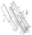
- FIG. 1 illustrates a multiple alignment connector assembly 10.
- Connector assembly 10 is comprised of a connector body 12 and a fiber alignment block, or ferrule 14.
- Connector body 12 is provided to transition optical fibers from an optical fiber cable (not shown in Figure 1) to ferrule 14.
- Ferrule 14 on the other hand, is provided to align the optical fibers and to directly interface with other compatible ferrules or with a number of different light emitting components such as LEDs, laser arrays, edge emitting lasers, super luminescent diodes, vertical cavity surface emitting laser (VCSELs) and other surface emitting devices. Additionally, ferrule 14 may interface with a number of different optoelectronic detectors.
- a ferrule cover 15 and a connector body cover 16 are provided for protecting optical fibers positioned there beneath. It should be noted, however, that covers 15 and 16 could be eliminated without departing from the scope of the present invention.
- connector body 12 and ferrule 14 are molded from standard engineering thermal plastics using known injection molding procedures.
- standard thermal plastics as opposed to other materials commonly used for connector ferrules such as ceramic, the cost of manufacturing ferrule 14 is greatly reduced. Additionally, the finishing steps for alignment details, such as grinding and polishing particularly required with ceramics, are eliminated.
- Connector body 12 has a front end 22 and a back end 24. A pair of projections 23 project from front end 22 for engagement with ferrule 14. Connector body 12 tapers from front end 22 to back end 24 and begins to taper at bevel line 26. Tapered back end 24 has a transition platform 25 which provides for a gentle transition from a fiber optic ribbon cable to connector body 12. Beneath connector body 16 is a connector body floor 28.
- Ferrule 14 has a connector body engagement surface (not shown), an optical fiber engaging surface 30, an optical device interface surface 32 and first and second alignment members 34 and 36, respectively.
- Connector body engagement surface has a pair of receiving cavities (not shown) for receiving projections 23.
- a plurality alignment grooves 38 are formed in fiber engagement surface 30 for aligning optical fibers.
- grooves 38 are V-shaped, however, other cross-sectional shapes could be chosen such as semicircular or rectangular without departing from the scope of the present invention.
- alignment grooves 38 are only found in the first few millimeters of ferrule 14. This provides the needed fiber alignment while reducing the cost and difficulty of the mold tooling.
- alignment grooves 38 may be located along the neutral axis of ferrule 14, thus minimizing the effect of angular misalignment of ferrule 14 on fiber alignment.
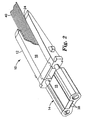
- Figure 2 is a perspective view of connector 10 having a plurality of optical fibers 40 retained beneath ferrule cover 15 and connector body cover 16 and bonded into alignment grooves 38.
- Bonding materials used in the present invention are commonly known, such as multi-part epoxy, or light curing adhesives such as ABLESTICK LUXTRAKTM LCR 0603B+UV.
- Optical fibers 40 may also be potted in grooves 38. As can be seen in Figure 2, optical fibers 40 are allowed to float between connector body floor 28 and connector body cover 16 and between back end 24 of connector body 12 and alignment grooves 38 of ferrule 14. This allows the fibers to buckle and bow without interference which assists in strain relief.
- strain relief features reference may be made to WO-A-97/46900.
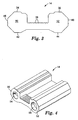
- Figure 3 is a front view of connector ferrule 14.
- first and second alignment members 34 and 36 are octagonally shaped members having bottom alignment edges 42 and 44 and side alignment edges 46 and 48, respectively. It should be noted, that first and second alignment members 34 and 36 could be many other shapes besides octagonal while still retaining the bottom and side alignment features without departing from the scope of the present invention such as hexagonal or rectangular. As can be seen in Figure 3, first and second alignment members 34 and 36 have first and second alignment faces 50 and 52, respectively, for alignment purposes as will be described in detail below.
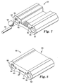
- Figure 4 is a perspective view of ferrule 14 prepared for ball and socket alignment.
- a first receiving cavity 54 is formed in first alignment face 50 and a second receiving cavity 56 is formed in second alignment face 52.
- First receiving cavity 54 is configured to form a chamfer for receiving and having secured inside it a portion of an alignment ball 58, as seen in Figure 7.
- Second receiving cavity 56 is sized to receive a substantial portion of an alignment ball, as will be described in detail below.
- alignment ball 58 is bonded into receiving cavity 54.
- Alignment ball 58 is provided to precisely align ferrule 14 which in turn precisely aligns the individual optical fibers.
- Alignment ball 58 is preferably a highly precise steel ball bearing but could also be formed from other materials having the precision of a steel ball bearing such as tungstoncarbide, ceramic, metal or plastic, such as liquid crystal polymer, without departing from the scope of the present invention.
- alignment ball 58 is bonded into receiving cavity 54. The bonding can be achieved by commonly known adhesives.
- Figure 5 illustrates a perspective view of connector ferrule 14 prepared for alignment pin alignment.
- a first alignment pin receiving cavity 60 is provided in first alignment face 50 while a second alignment pin receiving cavity 62 is provided in second alignment face 52.
- first alignment pin receiving cavity 60 is formed to receive and have bonded therein an alignment pin (not shown).
- Second receiving cavity 62 is sized to slidingly receive an alignment pin.
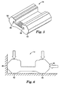
- Figure 6 is a front view of connector ferrule 14 in edge alignment.
- ferrule 14 is aligned utilizing first and second bottom alignment edges 42 and 44 and first side alignment edge 46.
- First and second bottom alignment edges 42 and 44 and first and second side alignment edges 46 and 48 are formed within the same mold portion as alignment grooves 38, thus maximizing the positional accuracy of V-grooves 38 relative to the ferrule edges and thus allowing ferrule 14 to be aligned based on its external geometry.
- ferrule 14 is very versatile. The same ferrule can be used for applications needing edge alignment and for connecting to a MTTM Connector having cylindrical alignment pins. Another ferrule equipped for alignment ball alignment may also be used for edge alignment.
- FIG. 7 is a perspective view of connector ferrule 61 according to a preferred embodiment of the invention and adapted as a universal ferrule capable of edge alignment, ball and socket alignment and pin alignment.
- Ferrule 14 contains features previously described, and thus like elements are correspondingly identified. In this embodiment, a single ferrule may be adapted for use in any of the three above-identified alignment methods.
- alignment ball 58 is bonded into first receiving cavity 54.
- an alignment pin 63 is inserted into first alignment pin receiving cavity 60. Pin 63 may be bonded in receiving cavity if desired.
- ferrule 61 may utilize edge alignment in the same manner as illustrated and described with respect to ferrule 14 in Figure 6.
- Ferrule 61 has the benefit of being adapted as a universal ferrule capable of the three alignment techniques described above. Therefore, a supplier would need only to stock ferrule 61 to accommodate a request from customers for edge alignment, ball and socket, or pin alignment. However, it should be pointed out that in order to accommodate both alignment pin receiving cavities 60 and 62 and ball and socket receiving cavities, 54 and 56, first and second alignment faces 50 and 52 are slightly larger than may be desired for certain applications.
- FIG 8 is a perspective view of an alternative embodiment of the present invention.
- a ferrule 65 is illustrated in Figure 8 which contains many features of ferrule 14, and thus like elements are correspondingly identified.
- ferrule cover 15 has become an integrally formed portion of ferrule 65, Grooves 38 have been removed and have been replaced with a plurality of holes 67.
- optical fibers are inserted through back end 69, and inserted through the length of ferrule 65, until the ends of the fibers are positioned co-planar to optical device interface surface 3 2. departing from the scope of the invention.
Landscapes
- Physics & Mathematics (AREA)
- General Physics & Mathematics (AREA)
- Optics & Photonics (AREA)
- Mechanical Coupling Of Light Guides (AREA)
Description
Claims (4)
- An optical fiber connector ferrule comprisinga fiber engaging and alignment surface (30) for engaging and aligning at least one optical fiber (40),wherein the fiber engagement and alignment surface (30) comprises at least one alignment groove (38),an optical device interface surface (32), andmultiple alignment means (34,36) for providing multiple alignment options for the connector ferrule (14), characterized in thatthe multiple alignment means further comprisesfirst and second alignment ball openings (54,56,60,62) formed in the optical device interface surface (32), wherein an alignment ball (58) is retained in the first alignment ball opening (54) and the second alignment ball opening (56) is sized to slidingly receive an alignment ball (58) when connecting with a device having the multiple alignment features of this claim andfirst and second alignment pin openings (60,62) formed in the optical device interface surface (32), wherein an alignment pin (63) is retained in the first alignment pin opening (60) and the second alignment pin opening (62) is sized to slidingly receive an alignment pin (63) when connecting with a device having the multiple alignment features of this claim.
- The fiber connector ferrule as in claim 1 wherein the multiple alignment means (34,36) comprises outer alignment edges (42,44,46,48) forming a portion of the outer geometry of the connector ferrule (14), wherein the alignment edges (42,44,46,48) are formed positionally accurate relative to the at least one alignment groove (38) to allow alignment of the connector ferrule (14) based on its external geometry.
- The connector ferrule as in claim 2, wherein the alignment means comprises first and second alignment members (34,36), wherein the first alignment member (34) has a first alignment face (50) and at least one of said outer alignment edges (42;46) and the second alignment member (36) has a second alignment face (52) and at least one of said outer alignment edge (44;48) said first and said second alignment faces forming part of said interface surface and wherein one of said alignment ball openings and one of said alignment pin openings (54;60) is formed in the first alignment face (50) and one of said alignment ball openings and one of said alignment pin openings (56;62) is formed in the second alignment face (52).
- The connector ferrule as in any one of claims 1 to 4 wherein the connector ferrule (14) is made of molded thermal plastic.
Applications Claiming Priority (3)
| Application Number | Priority Date | Filing Date | Title |
|---|---|---|---|
| US874243 | 1997-06-13 | ||
| US08/874,243 US5920670A (en) | 1996-06-07 | 1997-06-13 | Multiple alignment connector ferrule |
| PCT/US1997/018698 WO1998057208A1 (en) | 1997-06-13 | 1997-10-10 | Multiple alignment connector ferrule |
Publications (2)
| Publication Number | Publication Date |
|---|---|
| EP0988570A1 EP0988570A1 (en) | 2000-03-29 |
| EP0988570B1 true EP0988570B1 (en) | 2004-02-11 |
Family
ID=25363307
Family Applications (1)
| Application Number | Title | Priority Date | Filing Date |
|---|---|---|---|
| EP97913678A Expired - Lifetime EP0988570B1 (en) | 1997-06-13 | 1997-10-10 | Multiple alignment connector ferrule |
Country Status (7)
| Country | Link |
|---|---|
| US (1) | US5920670A (en) |
| EP (1) | EP0988570B1 (en) |
| JP (1) | JP2002504242A (en) |
| AU (1) | AU5080898A (en) |
| DE (1) | DE69727591T2 (en) |
| TW (1) | TW498172B (en) |
| WO (1) | WO1998057208A1 (en) |
Families Citing this family (36)
| Publication number | Priority date | Publication date | Assignee | Title |
|---|---|---|---|---|
| US6318902B1 (en) * | 1996-03-12 | 2001-11-20 | 3M Innovative Properties Company | Optical connector assembly using partial large diameter alignment features |
| US6805493B2 (en) | 1996-03-12 | 2004-10-19 | 3M Innovative Properties Company | Optical connector assembly using partial large diameter alignment features |
| US6328479B1 (en) * | 1999-05-24 | 2001-12-11 | Stratos Lightwave, Inc. | Multi-terminator optical interconnect system |
| US6601996B1 (en) | 1999-10-28 | 2003-08-05 | Corning Cable Systems Llc | Ferrule having alignment features for polishing operations and an associated polishing jig and method |
| US6480661B2 (en) * | 2000-03-03 | 2002-11-12 | The Whitaker Corporation | Optical ADD/DROP filter and method of making same |
| US6390690B1 (en) * | 2000-05-17 | 2002-05-21 | 3M Innovative Properties Company | Fiber optic connector for coupling devices on intersecting planes |
| US6520686B1 (en) | 2000-11-09 | 2003-02-18 | Teradyne, Inc. | Methods and apparatus for forming a fiber optic connection |
| US6799902B2 (en) | 2000-12-26 | 2004-10-05 | Emcore Corporation | Optoelectronic mounting structure |
| US6905260B2 (en) | 2000-12-26 | 2005-06-14 | Emcore Corporation | Method and apparatus for coupling optical elements to optoelectronic devices for manufacturing optical transceiver modules |
| US6867377B2 (en) | 2000-12-26 | 2005-03-15 | Emcore Corporation | Apparatus and method of using flexible printed circuit board in optical transceiver device |
| US6863444B2 (en) * | 2000-12-26 | 2005-03-08 | Emcore Corporation | Housing and mounting structure |
| US7021836B2 (en) | 2000-12-26 | 2006-04-04 | Emcore Corporation | Attenuator and conditioner |
| WO2003003522A2 (en) * | 2001-06-29 | 2003-01-09 | Xanoptix, Inc. | High-precision female format multifiber connector |
| US6623177B1 (en) | 2001-07-09 | 2003-09-23 | Emc Corporation | Systems and methods for providing fiber optic communications between circuit boards |
| US6682228B2 (en) | 2002-02-19 | 2004-01-27 | Emcore Corporation | Connector housing for fiber-optic module |
| US6722791B2 (en) * | 2002-04-19 | 2004-04-20 | Hon Hai Precision Ind. Co., Ltd. | Multi-fiber ferrule |
| US6839935B2 (en) * | 2002-05-29 | 2005-01-11 | Teradyne, Inc. | Methods and apparatus for cleaning optical connectors |
| US6762941B2 (en) | 2002-07-15 | 2004-07-13 | Teradyne, Inc. | Techniques for connecting a set of connecting elements using an improved latching apparatus |
| JP3989316B2 (en) * | 2002-07-15 | 2007-10-10 | 株式会社巴川製紙所 | Optical fiber connection method and optical fiber connection structure |
| US6832858B2 (en) * | 2002-09-13 | 2004-12-21 | Teradyne, Inc. | Techniques for forming fiber optic connections in a modularized manner |
| US7042562B2 (en) * | 2002-12-26 | 2006-05-09 | Amphenol Corp. | Systems and methods for inspecting an optical interface |
| US6863453B2 (en) | 2003-01-28 | 2005-03-08 | Emcore Corporation | Method and apparatus for parallel optical transceiver module assembly |
| US6973242B2 (en) * | 2003-04-17 | 2005-12-06 | 3M Innovative Properties Company | Apparatus useful for guiding fiber optic ribbons into ferrules |
| US7108431B2 (en) * | 2003-04-17 | 2006-09-19 | 3M Innovative Properties Company | Ferrule for use in fiber optic connectors |
| EP1869737B1 (en) * | 2005-03-16 | 2021-05-12 | Davidson Instruments, Inc. | High intensity fabry-perot sensor |
| US8432552B2 (en) * | 2005-03-16 | 2013-04-30 | Halliburton Energy Services, Inc. | High intensity Fabry-Perot sensor |
| WO2008112220A1 (en) * | 2007-03-08 | 2008-09-18 | Davidson Instruments Inc. | Apparatus and methods for monitoring combustion dynamics in a gas turbine engine |
| US8337095B2 (en) * | 2009-09-30 | 2012-12-25 | Corning Cable Systems Llc | Tapered-channel ferrules and optical fiber connectors employing same |
| WO2012111650A1 (en) * | 2011-02-17 | 2012-08-23 | 古河電気工業株式会社 | Ferrule for optical connector |
| US10215926B2 (en) | 2011-12-14 | 2019-02-26 | Commscope Technologies Llc | Multi-fiber fiber optic connection system with flexible, insertable pins |
| US9360634B2 (en) * | 2012-12-05 | 2016-06-07 | Ofs Fitel, Llc | Structures and techniques for aligning a multicore fiber in a ferrule or production jig |
| TW201624033A (en) * | 2014-09-12 | 2016-07-01 | 費雪曼股份有限公司 | Fiber optic connector assembly fixture |
| US10162126B2 (en) | 2014-12-01 | 2018-12-25 | Commscope Asia Holdings B.V. | Multi-fiber optic connector with pivotally-aligned ferrule and resilient alignment pins |
| US10203457B2 (en) | 2015-06-19 | 2019-02-12 | Commscope Technologies Llc | Fiber optic connector ferrule with improved alignment mechanism |
| US11573377B2 (en) * | 2015-10-12 | 2023-02-07 | 3M Innovative Properties Company | Optical waveguide positioning feature in a multiple waveguides connector |
| US12455416B2 (en) * | 2020-08-28 | 2025-10-28 | Commscope Technologies Llc | Low profile fiber holders for use with bare fiber multi-fiber fiber optic connectors |
Citations (3)
| Publication number | Priority date | Publication date | Assignee | Title |
|---|---|---|---|---|
| DE3409641A1 (en) * | 1984-03-16 | 1985-09-19 | Standard Elektrik Lorenz Ag, 7000 Stuttgart | Demountable connection for optical fibres |
| US4784457A (en) * | 1986-03-11 | 1988-11-15 | Siemens Aktiengesellschaft | Connector device for light waveguides held with an adhesive |
| US5416868A (en) * | 1991-09-09 | 1995-05-16 | Sumitomo Electric Industries, Ltd. | Optical connector having a resin molding portion which includes opposite opened portions at top and bottom surfaces |
Family Cites Families (10)
| Publication number | Priority date | Publication date | Assignee | Title |
|---|---|---|---|---|
| US5199093A (en) * | 1990-05-22 | 1993-03-30 | Bicc Plc. | Multi-part optical fibre connectors |
| US5155784A (en) * | 1990-11-07 | 1992-10-13 | Bicc Plc | Optical connection to backplanes |
| AU635172B2 (en) * | 1991-05-13 | 1993-03-11 | Nippon Telegraph & Telephone Corporation | Multifiber optical connector plug with low reflection and low insertion loss |
| US5287426A (en) * | 1993-02-22 | 1994-02-15 | At&T Bell Laboratories | Methods for making optical fiber connectors |
| JPH06337328A (en) * | 1993-03-29 | 1994-12-06 | Sumitomo Electric Ind Ltd | Optical connector |
| US5430819A (en) * | 1993-12-21 | 1995-07-04 | At&T Corp. | Multiple optical fiber connector and method of making same |
| JPH07261121A (en) * | 1994-03-18 | 1995-10-13 | Tdk Corp | Optical fiber terminal with optical isolator |
| US5619604A (en) * | 1996-02-26 | 1997-04-08 | Alcoa Fujikura Limited | Multi-fiber optical connector |
| US5778123A (en) * | 1996-03-12 | 1998-07-07 | Minnesota Mining And Manufacturing Company | Alignment assembly for multifiber or single fiber optical cable connector |
| US5727097A (en) * | 1996-06-07 | 1998-03-10 | Minnesota Mining And Manufacturing Company | Pull-proof fiber optic array connector |
-
1997
- 1997-06-13 US US08/874,243 patent/US5920670A/en not_active Expired - Fee Related
- 1997-10-10 EP EP97913678A patent/EP0988570B1/en not_active Expired - Lifetime
- 1997-10-10 WO PCT/US1997/018698 patent/WO1998057208A1/en not_active Ceased
- 1997-10-10 AU AU50808/98A patent/AU5080898A/en not_active Abandoned
- 1997-10-10 DE DE69727591T patent/DE69727591T2/en not_active Expired - Fee Related
- 1997-10-10 JP JP50235699A patent/JP2002504242A/en not_active Withdrawn
-
1998
- 1998-05-15 TW TW087107546A patent/TW498172B/en active
Patent Citations (3)
| Publication number | Priority date | Publication date | Assignee | Title |
|---|---|---|---|---|
| DE3409641A1 (en) * | 1984-03-16 | 1985-09-19 | Standard Elektrik Lorenz Ag, 7000 Stuttgart | Demountable connection for optical fibres |
| US4784457A (en) * | 1986-03-11 | 1988-11-15 | Siemens Aktiengesellschaft | Connector device for light waveguides held with an adhesive |
| US5416868A (en) * | 1991-09-09 | 1995-05-16 | Sumitomo Electric Industries, Ltd. | Optical connector having a resin molding portion which includes opposite opened portions at top and bottom surfaces |
Also Published As
| Publication number | Publication date |
|---|---|
| EP0988570A1 (en) | 2000-03-29 |
| JP2002504242A (en) | 2002-02-05 |
| DE69727591T2 (en) | 2004-12-16 |
| US5920670A (en) | 1999-07-06 |
| TW498172B (en) | 2002-08-11 |
| AU5080898A (en) | 1998-12-30 |
| DE69727591D1 (en) | 2004-03-18 |
| WO1998057208A1 (en) | 1998-12-17 |
Similar Documents
| Publication | Publication Date | Title |
|---|---|---|
| EP0988570B1 (en) | Multiple alignment connector ferrule | |
| US5778123A (en) | Alignment assembly for multifiber or single fiber optical cable connector | |
| EP0928978B1 (en) | Connector for plastic optical fiber | |
| US20210109293A1 (en) | Multi-fiber ferrule-less duplex fiber optic connectors with multi-fiber alignment devices | |
| US4142776A (en) | Optical fiber ribbon cartridge connector | |
| US6045270A (en) | Massive parallel optical interconnect system | |
| US4715675A (en) | Fiber optic ferrule | |
| US5519799A (en) | Optical fiber array structure | |
| CN1313955A (en) | Multi-terminator optical interconnect system | |
| US6367985B1 (en) | Optical connector using large diameter alignment features | |
| US6722791B2 (en) | Multi-fiber ferrule | |
| WO2020081439A1 (en) | Ferrules including keying features and fiber optic junctions including the same | |
| EP1312951B1 (en) | Optical connector adapter for interfacing single or multichannel waveguide devices to fiber and method of forming same | |
| GB2032642A (en) | Fibre optic connector | |
| CN87104804A (en) | Connector for detachable connection of light conducting fibres | |
| US6964525B2 (en) | Optical connector and backplane assembly | |
| EP1039324A1 (en) | Conductor guiding device for connector plug | |
| CZ12248U1 (en) | Assembly of optical connector with fixedly mounted ferrule and spring-loaded adapter | |
| AU755885B2 (en) | Massive parallel optical interconnect system | |
| US12429652B2 (en) | Multi-fiber semi-permanent splicing systems |
Legal Events
| Date | Code | Title | Description |
|---|---|---|---|
| PUAI | Public reference made under article 153(3) epc to a published international application that has entered the european phase |
Free format text: ORIGINAL CODE: 0009012 |
|
| 17P | Request for examination filed |
Effective date: 19991207 |
|
| AK | Designated contracting states |
Kind code of ref document: A1 Designated state(s): DE FR GB IT |
|
| 17Q | First examination report despatched |
Effective date: 20001122 |
|
| GRAP | Despatch of communication of intention to grant a patent |
Free format text: ORIGINAL CODE: EPIDOSNIGR1 |
|
| GRAS | Grant fee paid |
Free format text: ORIGINAL CODE: EPIDOSNIGR3 |
|
| GRAA | (expected) grant |
Free format text: ORIGINAL CODE: 0009210 |
|
| AK | Designated contracting states |
Kind code of ref document: B1 Designated state(s): DE FR GB IT |
|
| PG25 | Lapsed in a contracting state [announced via postgrant information from national office to epo] |
Ref country code: IT Free format text: LAPSE BECAUSE OF FAILURE TO SUBMIT A TRANSLATION OF THE DESCRIPTION OR TO PAY THE FEE WITHIN THE PRESCRIBED TIME-LIMIT;WARNING: LAPSES OF ITALIAN PATENTS WITH EFFECTIVE DATE BEFORE 2007 MAY HAVE OCCURRED AT ANY TIME BEFORE 2007. THE CORRECT EFFECTIVE DATE MAY BE DIFFERENT FROM THE ONE RECORDED. Effective date: 20040211 |
|
| REG | Reference to a national code |
Ref country code: GB Ref legal event code: FG4D |
|
| REF | Corresponds to: |
Ref document number: 69727591 Country of ref document: DE Date of ref document: 20040318 Kind code of ref document: P |
|
| ET | Fr: translation filed | ||
| PLBE | No opposition filed within time limit |
Free format text: ORIGINAL CODE: 0009261 |
|
| STAA | Information on the status of an ep patent application or granted ep patent |
Free format text: STATUS: NO OPPOSITION FILED WITHIN TIME LIMIT |
|
| 26N | No opposition filed |
Effective date: 20041112 |
|
| PGFP | Annual fee paid to national office [announced via postgrant information from national office to epo] |
Ref country code: GB Payment date: 20051005 Year of fee payment: 9 |
|
| PGFP | Annual fee paid to national office [announced via postgrant information from national office to epo] |
Ref country code: FR Payment date: 20051017 Year of fee payment: 9 |
|
| PGFP | Annual fee paid to national office [announced via postgrant information from national office to epo] |
Ref country code: DE Payment date: 20051130 Year of fee payment: 9 |
|
| PG25 | Lapsed in a contracting state [announced via postgrant information from national office to epo] |
Ref country code: DE Free format text: LAPSE BECAUSE OF NON-PAYMENT OF DUE FEES Effective date: 20070501 |
|
| GBPC | Gb: european patent ceased through non-payment of renewal fee |
Effective date: 20061010 |
|
| REG | Reference to a national code |
Ref country code: FR Ref legal event code: ST Effective date: 20070629 |
|
| PG25 | Lapsed in a contracting state [announced via postgrant information from national office to epo] |
Ref country code: GB Free format text: LAPSE BECAUSE OF NON-PAYMENT OF DUE FEES Effective date: 20061010 |
|
| PG25 | Lapsed in a contracting state [announced via postgrant information from national office to epo] |
Ref country code: FR Free format text: LAPSE BECAUSE OF NON-PAYMENT OF DUE FEES Effective date: 20061031 |