EP0987573A1 - Verbindungsdose - Google Patents
Verbindungsdose Download PDFInfo
- Publication number
- EP0987573A1 EP0987573A1 EP98203147A EP98203147A EP0987573A1 EP 0987573 A1 EP0987573 A1 EP 0987573A1 EP 98203147 A EP98203147 A EP 98203147A EP 98203147 A EP98203147 A EP 98203147A EP 0987573 A1 EP0987573 A1 EP 0987573A1
- Authority
- EP
- European Patent Office
- Prior art keywords
- fibre
- front panel
- junction box
- guide
- plate
- Prior art date
- Legal status (The legal status is an assumption and is not a legal conclusion. Google has not performed a legal analysis and makes no representation as to the accuracy of the status listed.)
- Withdrawn
Links
- 239000000835 fiber Substances 0.000 claims abstract description 70
- 239000004020 conductor Substances 0.000 claims abstract description 61
- 125000006850 spacer group Chemical group 0.000 claims description 2
- 230000008878 coupling Effects 0.000 description 11
- 238000010168 coupling process Methods 0.000 description 11
- 238000005859 coupling reaction Methods 0.000 description 11
- 230000001154 acute effect Effects 0.000 description 1
- XAGFODPZIPBFFR-UHFFFAOYSA-N aluminium Chemical compound [Al] XAGFODPZIPBFFR-UHFFFAOYSA-N 0.000 description 1
- 229910052782 aluminium Inorganic materials 0.000 description 1
- 239000004411 aluminium Substances 0.000 description 1
- 238000003780 insertion Methods 0.000 description 1
- 230000037431 insertion Effects 0.000 description 1
- 238000004519 manufacturing process Methods 0.000 description 1
- 239000000463 material Substances 0.000 description 1
- 230000000717 retained effect Effects 0.000 description 1
Images


Classifications
-
- G—PHYSICS
- G02—OPTICS
- G02B—OPTICAL ELEMENTS, SYSTEMS OR APPARATUS
- G02B6/00—Light guides; Structural details of arrangements comprising light guides and other optical elements, e.g. couplings
- G02B6/44—Mechanical structures for providing tensile strength and external protection for fibres, e.g. optical transmission cables
- G02B6/4439—Auxiliary devices
- G02B6/444—Systems or boxes with surplus lengths
- G02B6/4453—Cassettes
-
- G—PHYSICS
- G02—OPTICS
- G02B—OPTICAL ELEMENTS, SYSTEMS OR APPARATUS
- G02B6/00—Light guides; Structural details of arrangements comprising light guides and other optical elements, e.g. couplings
- G02B6/44—Mechanical structures for providing tensile strength and external protection for fibres, e.g. optical transmission cables
- G02B6/4439—Auxiliary devices
- G02B6/444—Systems or boxes with surplus lengths
- G02B6/4452—Distribution frames
- G02B6/44526—Panels or rackmounts covering a whole width of the frame or rack
Definitions
- the present invention relates to a cross junction box for fibre optic cables with a number of fibre conductors, and comprising a front panel with a terminal for each fibre conductor or pair thereof, each terminal having, on the rear side of the front panel, connection means for connecting the fibre conductor.
- Cross junction boxes for fibre optic cables are previously known in the art and are employed in such contexts where the individual optic fibre conductors in each cable are to be capable of being interconnected with any optional fibre conductor in another cable.
- the cross junction boxes have a front panel with a terminal for each fibre conductor or pair thereof.
- the fibre conductor is connected interiorly in the cross junction box to a coupling device on the terminal, it being possible, on the outside of the cross junction box, to conned a "jump terminal" consisting of a fibre conductor to another terminal either in the actual cross junction box or in another, proximal cross junction box.
- Fibre optics are extremely sensitive as regards precision, attack by dirt and possible movements or play in couplings, connections etc. For this reason, it often happens that the coupling device between the terminal and a specific fibre conductor must be opened so that the coupling device and the end of the fibre conductor can be cleaned or adjusted.
- a junction box with 24 or 28 connecting devices and as many fibre conductors it is close to impossible to access and service a fibre conductor and a corresponding connecting device without the traffic being disrupted on adjacent fibre conductors. Further, the purely physical accessibility for the coupling devices and the individual fibre conductors is extremely limited.
- junction box proper is open upwards and as a unit is withdrawable from the rack in which it is generally mounted, accessibility is hardly improved for the fibre conductors and their coupling devices.
- the present invention has for its object to design the cross junction box intimated by way of introduction in such a manner that service of individual fibre conductors and their coupling devices is greatly facilitated.
- the present invention also has for its object to design the cross junction box in such a manner that the risk of disruption to fibre conductors in operation is reduced to a extremely high degree or entirely obviated in connection with service on another fibre conductor or its coupling device.
- the present invention has for its object to design the cross junction box such that it will be simple and economical in manufacture and aesthetically attractive.
- the cross junction box disclosed by way of introduction is characterized in that the terminals each have their own holder which is individually withdrawable to a service position outside the front panel, and that in this position and end portion of the relevant fibre conductor or pair thereof and their coupling devices are located outside the front panel.
- cross junction box is also given one or more of the characterizing features as set forth in appended Claims 2 to 6.
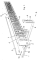
- reference numeral 1 relates to the bottom of a cross junction box which has a front panel 2 and a rear or inner defining wall 3.
- the inner wall 3, the bottom 1 and the front panel 2 may be manufactured, for example, from sheet material or be in the from of an extruded aluminium profile.
- the front panel 2 has a series of openings 4 which, in the illustrated embodiment, are aligned in a row of twenty-four.
- the openings 4 are intended for mounting of terminals designed in such a manner that, on the front side of the front panel 2, they display connecting devices for a fibre optic jump connection and that on the inside of the front panel, they have coupling devices for connection of a fibre conductor.
- the terminals are designed as double terminals which, in positions over one another, can connect two fibre conductors.
- a holder 5 which has a short shank 6 which is designed as holder or retainer shank for mounting the terminal and which has a rear side which is intended to be able to abut against the outside of the front panel 2. This is shown, for example, at reference numeral 7.
- Each holder 5 further displays a lower or horizontal shank 8 which functions as withdrawal shank and which extends through an opening 9 in the front panel 2 (see Fig. 3).
- the lower shank 8 is slidable through the opening between the operational position intimated at reference numeral 7 and the withdrawal or service position at reference numeral 6.
- An intermediate position is intimated by reference numeral 10.
- the shanks 6, 7 and 10 on the holders 5 have apertures 11 which correspond to the openings 4 in the front panel 2.
- the above mentioned upwardly directed shanks in the holders 5 serve for mounting the previously mentioned terminals so that these are fixedly mounted on the holders.
- the cross junction box has interiorly a fibre conductor space 12 in which are located 24 or 48 (in the illustrated embodiment) fibre conductors 13 (see Fig. 2) which lie freely and extend out from one end of a fibre optic cable 14 (see Fig. 2).
- a fibre conductor space 12 in which are located 24 or 48 (in the illustrated embodiment) fibre conductors 13 (see Fig. 2) which lie freely and extend out from one end of a fibre optic cable 14 (see Fig. 2).
- There is often a second ingoing/outgoing cable which is disposed at the opposing short side of the box and approximately mirror-reversed to that shown for the cable 14 and the fibre conductor 13. It will therefore readily be perceived that the space available interiorly in the fibre conductor space 12 is limited and, consequently, withdrawal or insertion of a lower shank 8 on a holder 5 could very easily mechanically affect and disrupt one or more of the fibre conductors 13.
- the lower shanks 8 are disposed on the under side of a plate 15 with a substantially planar and smooth upper side. It should, for example, be observed that the anchorage screws 16 of the plate 15 in the bottom 1 are countersunk. The plate 15 is retained at the correct distance above the bottom 1 by the intermediary of spacers 17 which are shown in Fig. 3.
- the shanks are provided at their inner ends with suitable arrest means 18 in the form of screws (see Fig. 3).
- the screws 18 further serve to guide in the vertical direction the inner end of the lower shank 8 so that this may move substantially without play between the upper side of the bottom 1 and the underside of the plate 15.
- a guide 19 for guiding the individual fibre conductors the guide to each fibre conductor being provided with engagement means 21 such that the fibre conductors are restrictedly movable and displaceable in their longitudinal direction.
- the fibre conductors are well localised in relation to the guide and in relation to adjacent fibre conductors cooperating with the guide.
- the guide 19 is strip shaped and is secured on the upper side of the plate 15 along the edge thereof running against the front panel 2.
- the guide 19 has an upwardly angled portion 20 which makes an acute angle with the upper side of the plate 15 and which is located a slight distance above it.
- the above mentioned engagement means 21 in the guide 19 comprise a slot 22 which extends in from the edge of the guide facing away from the front panel 2 and which, in its inner end, has an aperture 23 whose transverse dimension or diameter is somewhat larger than the transverse dimension or diameter of the individual fibre conductor 13. It will be apparent from Fig. 2 that the slots 22 are disposed alternatingly with different lengths.
- Fig. 2 shows how an individual fibre conductor 13 is passed interiorly in the cross junction box. From the incoming / outgoing fibre optic cable 14, the fibre conductor 13 extends along the edge of the plate 15 facing away from the front panel 2 in a loop away to the opposite short end of the plate 15. Here, the fibre conductor 13 turns back in a loop 24 and is located on the under side of the guide 19 in order to pass up through an aperture 23 in it. On the upper side of the guide 19, the fibre conductor then runs in a new loop 25 away to the incoming / outgoing cable 14 in order thence to be gently bent to a direction which is approximately at right angles to the plane of the front panel 2 and, in the service position, out through the opening 4 of the front panel 2.
- the fibre conductor 13 runs with its distal loop 24 in Fig. 2 closer to the distal end of the plate 15 in that the fibre conductor 13 has been displaced somewhat through the aperture 23.
- the proximal loop 25 of the fibre conductor 13 will be more bent in a direction towards the inner wall 3.
Landscapes
- Physics & Mathematics (AREA)
- General Physics & Mathematics (AREA)
- Optics & Photonics (AREA)
- Light Guides In General And Applications Therefor (AREA)
Priority Applications (1)
| Application Number | Priority Date | Filing Date | Title |
|---|---|---|---|
| EP98203147A EP0987573A1 (de) | 1998-09-18 | 1998-09-18 | Verbindungsdose |
Applications Claiming Priority (1)
| Application Number | Priority Date | Filing Date | Title |
|---|---|---|---|
| EP98203147A EP0987573A1 (de) | 1998-09-18 | 1998-09-18 | Verbindungsdose |
Publications (1)
| Publication Number | Publication Date |
|---|---|
| EP0987573A1 true EP0987573A1 (de) | 2000-03-22 |
Family
ID=8234137
Family Applications (1)
| Application Number | Title | Priority Date | Filing Date |
|---|---|---|---|
| EP98203147A Withdrawn EP0987573A1 (de) | 1998-09-18 | 1998-09-18 | Verbindungsdose |
Country Status (1)
| Country | Link |
|---|---|
| EP (1) | EP0987573A1 (de) |
Cited By (1)
| Publication number | Priority date | Publication date | Assignee | Title |
|---|---|---|---|---|
| CN107846802A (zh) * | 2017-12-15 | 2018-03-27 | 无锡优耐特能源科技有限公司 | 一种用于机箱进线的电缆导引装置 |
Citations (3)
| Publication number | Priority date | Publication date | Assignee | Title |
|---|---|---|---|---|
| FR2515466A1 (fr) * | 1981-10-23 | 1983-04-29 | Lignes Telegraph Telephon | Dispositif de raccordement d'un cable de transmission, notamment d'un cable a fibres optiques, a des equipements electroniques |
| EP0146478A2 (de) * | 1983-12-20 | 1985-06-26 | Lignes Telegraphiques Et Telephoniques L.T.T. | Vorrichtung zur Kupplung von Kabeln besonders optischen Fasern |
| EP0408266A2 (de) * | 1989-07-11 | 1991-01-16 | BICC Public Limited Company | Abschlusssystem für optische Fasern |
-
1998
- 1998-09-18 EP EP98203147A patent/EP0987573A1/de not_active Withdrawn
Patent Citations (3)
| Publication number | Priority date | Publication date | Assignee | Title |
|---|---|---|---|---|
| FR2515466A1 (fr) * | 1981-10-23 | 1983-04-29 | Lignes Telegraph Telephon | Dispositif de raccordement d'un cable de transmission, notamment d'un cable a fibres optiques, a des equipements electroniques |
| EP0146478A2 (de) * | 1983-12-20 | 1985-06-26 | Lignes Telegraphiques Et Telephoniques L.T.T. | Vorrichtung zur Kupplung von Kabeln besonders optischen Fasern |
| EP0408266A2 (de) * | 1989-07-11 | 1991-01-16 | BICC Public Limited Company | Abschlusssystem für optische Fasern |
Cited By (2)
| Publication number | Priority date | Publication date | Assignee | Title |
|---|---|---|---|---|
| CN107846802A (zh) * | 2017-12-15 | 2018-03-27 | 无锡优耐特能源科技有限公司 | 一种用于机箱进线的电缆导引装置 |
| CN107846802B (zh) * | 2017-12-15 | 2023-06-23 | 无锡优耐特能源科技有限公司 | 一种用于机箱进线的电缆导引装置 |
Similar Documents
| Publication | Publication Date | Title |
|---|---|---|
| US6541705B1 (en) | Cable management rack | |
| US20030223723A1 (en) | Reconfigurable fiber optic cable management enclosure | |
| EP1377862B1 (de) | Verteiler für optische fasern | |
| US5978540A (en) | Apparatus for interconnecting optical fibers | |
| EP1455542B1 (de) | Baugruppenträger mit Kabelverwalter | |
| US6866541B2 (en) | Angled patch panel with cable support bar for network cable racks | |
| DE69207745T2 (de) | Stütz- und Führungsgerüst für elektrische und optische Übertragungskabeln | |
| US6515227B1 (en) | Fiber optic cable management enclosure with integral bend radius control | |
| US6256444B1 (en) | Adjustable guide for organizing optical fibers in an equipment rack | |
| US7826705B2 (en) | Parking device for fiber distribution hub | |
| KR100730622B1 (ko) | 네트워크 랙용 케이블 매니저 | |
| DE69125002T2 (de) | Faseroptisches verteilungsgestell | |
| US5689606A (en) | Fiber routing and retention assembly with modular fiber connector support | |
| EP1160605A2 (de) | Glasfaserverzweigungs- und -verteilungssystem | |
| EP3528023B1 (de) | Spleissmodul mit patcheinheit | |
| GB2464186A (en) | Telecommunications patching system with vertically-oriented patching modules | |
| US20160134092A1 (en) | Strain relief device for low friction drop cable | |
| US4850901A (en) | Communications outlet | |
| EP1120674B1 (de) | Schaltfeld zur Verbindung von Glasfaserkabeln | |
| CA2313895A1 (en) | Mounting apparatus for equipment enclosures having cable bend radius control and channel for retaining cable | |
| US5175673A (en) | Distributor for use in communication systems | |
| US6671447B1 (en) | Optical fiber organizer for organizing optical fiber inside of a fiber duct | |
| EP0987573A1 (de) | Verbindungsdose | |
| US20020131751A1 (en) | FIber optic cable restraint | |
| US7876995B2 (en) | Telecommunications patching systems with obliquely-angled patching modules |
Legal Events
| Date | Code | Title | Description |
|---|---|---|---|
| PUAI | Public reference made under article 153(3) epc to a published international application that has entered the european phase |
Free format text: ORIGINAL CODE: 0009012 |
|
| AK | Designated contracting states |
Kind code of ref document: A1 Designated state(s): BE DE ES FI FR GB IT NL |
|
| AX | Request for extension of the european patent |
Free format text: AL;LT;LV;MK;RO;SI |
|
| 17P | Request for examination filed |
Effective date: 20000922 |
|
| AKX | Designation fees paid |
Free format text: BE DE ES FI FR GB IT NL |
|
| RTI1 | Title (correction) |
Free format text: FIBRE OPTIC CROSS JUNCTION BOX |
|
| GRAP | Despatch of communication of intention to grant a patent |
Free format text: ORIGINAL CODE: EPIDOSNIGR1 |
|
| STAA | Information on the status of an ep patent application or granted ep patent |
Free format text: STATUS: THE APPLICATION IS DEEMED TO BE WITHDRAWN |
|
| 18D | Application deemed to be withdrawn |
Effective date: 20070417 |