EP0987172A2 - Top-box for motorcycles - Google Patents
Top-box for motorcycles Download PDFInfo
- Publication number
- EP0987172A2 EP0987172A2 EP99500150A EP99500150A EP0987172A2 EP 0987172 A2 EP0987172 A2 EP 0987172A2 EP 99500150 A EP99500150 A EP 99500150A EP 99500150 A EP99500150 A EP 99500150A EP 0987172 A2 EP0987172 A2 EP 0987172A2
- Authority
- EP
- European Patent Office
- Prior art keywords
- shell
- lower half
- box
- inserting element
- projection
- Prior art date
- Legal status (The legal status is an assumption and is not a legal conclusion. Google has not performed a legal analysis and makes no representation as to the accuracy of the status listed.)
- Granted
Links
Images


Classifications
-
- B—PERFORMING OPERATIONS; TRANSPORTING
- B62—LAND VEHICLES FOR TRAVELLING OTHERWISE THAN ON RAILS
- B62J—CYCLE SADDLES OR SEATS; AUXILIARY DEVICES OR ACCESSORIES SPECIALLY ADAPTED TO CYCLES AND NOT OTHERWISE PROVIDED FOR, e.g. ARTICLE CARRIERS OR CYCLE PROTECTORS
- B62J9/00—Containers specially adapted for cycles, e.g. panniers or saddle bags
- B62J9/20—Containers specially adapted for cycles, e.g. panniers or saddle bags attached to the cycle as accessories
- B62J9/24—Containers specially adapted for cycles, e.g. panniers or saddle bags attached to the cycle as accessories on specially adapted racks, e.g. for top or side cases
-
- B—PERFORMING OPERATIONS; TRANSPORTING
- B62—LAND VEHICLES FOR TRAVELLING OTHERWISE THAN ON RAILS
- B62J—CYCLE SADDLES OR SEATS; AUXILIARY DEVICES OR ACCESSORIES SPECIALLY ADAPTED TO CYCLES AND NOT OTHERWISE PROVIDED FOR, e.g. ARTICLE CARRIERS OR CYCLE PROTECTORS
- B62J6/00—Arrangement of optical signalling or lighting devices on cycles; Mounting or supporting thereof; Circuits therefor
-
- B—PERFORMING OPERATIONS; TRANSPORTING
- B62—LAND VEHICLES FOR TRAVELLING OTHERWISE THAN ON RAILS
- B62J—CYCLE SADDLES OR SEATS; AUXILIARY DEVICES OR ACCESSORIES SPECIALLY ADAPTED TO CYCLES AND NOT OTHERWISE PROVIDED FOR, e.g. ARTICLE CARRIERS OR CYCLE PROTECTORS
- B62J9/00—Containers specially adapted for cycles, e.g. panniers or saddle bags
- B62J9/30—Containers specially adapted for cycles, e.g. panniers or saddle bags characterised by locking arrangements, e.g. top case locks integrated in a vehicle central locking system
Definitions
- the present invention relates to a top-box for motorcycles, of the type that comprises a lower half-shell and an upper half-shell which together form an interior chamber.
- the lower half-shell is usually fixed to the structure of the motorcycle frame, and particularly to the subframe, by means of a base support.
- top-boxes on motorcycles makes it essential to fit means of securing or locking the box to prevent it being opened in order to gain access to the objects stowed inside it.
- the applicant for the present application is also proprietor of Spanish utility models 9402766 and 9402767.
- the first utility model mentioned relates to a locking mechanism.
- Said locking mechanism includes an opening lever that is hinged onto the half-shell fitted with the lock which blocks the movement of the lever.
- the second utility model mentioned describes a mechanism for securing and locking motorcycle top-boxes.
- This mechanism basically includes a piece that hooks the upper half-shell which is mounted attached to the lower half-shell by means of a piece acting as a connecting rod.
- Said lower half-shell is also fitted with fold-down handle hinged onto it to make it easier to carry the top-box.
- One objective of the present invention is to provide a secure and reliable top-box for motorcycles capable of effectively guaranteeing its inviolability, thereby offering an effective means of carrying objects, while at the same time being simple from a functional and constructional point of view.
- top-box of the invention which will be described below. Furthermore, said top-box presents other advantages which will become clear from the description which follows.
- the motorcycle top-box of the invention essentially comprises a lower half-shell and an upper half-shell that together form an interior chamber.
- the upper half-shell can tilt with respect to the lower half-shell.
- Said half-shells have locking means to prevent opening of the upper half-shell with respect to the lower half-shell.
- Said locking means include an inserting element attached to the lower half-shell and a receiving element attached to the upper half-shell.
- the special feature of the motorcycle top-box of the invention lies in the fact that the inserting element is hinged on the lower half-shell.
- the hinging of the inserting element is implemented in such a way that the element can move in a direction substantially perpendicular to the face of the lower half-shell to which said element is attached.
- the inserting element includes elastic means for insertion under pressure into the receiving element.
- the lower half-shell is provided with means for driving the inserting element in order to release the two half-shells from each other.
- the combined arrangement of the hinged attachment of the inserting element on the lower half-shell and the driving means of the inserting element considerably facilitate opening of the box by the user. Furthermore, the described arrangement of the locking means achieves effective locking of the box since it is considerably more difficult to violate than are the known top-boxes.
- the driving means include a lever hinged onto the lower half-shell and connected operatively with a rod that acts on the inserting element.
- the driving means are thus simplified considerably, while an effective way of opening the box is provided since the locking or securing of the half-shells is carried out more securely, as mentioned above.
- the locking means include a pair of inserting elements and a pair of receiving elements so that the securing operation is carried out by acting on two points of the top-box to ensure firm securing.
- the inserting element is a plate hinged onto the lower half-shell and provided with a projection on its top part.
- the receiving element includes a plate provided with an orifice in which the aforesaid projection is inserted.
- the aforesaid projection of the inserting element advantageously includes a protuberance that forms an inclined plane providing a slope designed to facilitate insertion of the inserting element. It is thus sufficient to apply only slight pressure on the upper half-shell so that the plate of said half-shell slides suitably on the surface of the aforesaid slope, forcing the plate of the lower half-shell to detach slightly from it and allowing its projection to be inserted into the orifice of the receiving element.
- the invention also provides for incorporation into the lower half-shell of a power socket supplied from the motorcycle so as to be able to plug into the top-box items that work with electricity, such as light fitments.
- the upper part of the exterior of the upper half-shell is designed for installing lighting means powered from the power socket of the lower half-shell.
- the aforesaid socket can include an electrical contact element consisting, for example, of a threaded terminal on the lower half-shell provided with a rounded head designed to make contact with a contacting element consisting of flats fitted on the base plate of the top-box.
- the top-box is fixed onto the motorcycle, and more specifically onto its subframe, by attaching the lower half-shell onto the aforesaid base plate.
- the upper end of the contacting flats which are to a certain extent flexible, move to one side as they slide on the surface of the terminal.
- the contact between the terminal and the flats permits the passage of electrical current from the motorcycle to a cable connected to said terminal. This cable allows power to be supplied to the aforesaid lighting means situated on the top part of the outside of the upper half-shell.
- top-box of the invention for motorcycles
- the description in question relates to the drawings attached, the objective of which is to clarify the description of the matters set out above in this specification.
- Other embodiments of the top-box of the invention will be obvious to an expert on the subject, all of which embodiments are included within the sphere of this invention.
- a top-box for motorcycles in accordance with this invention includes a lower half-shell 1 and an upper half-shell 2.
- the lower half-shell 1 is usually attached to a base plate (not shown in the figures) which is in turn fixed to the subframe of the motorcycle.
- the half-shells 1,2 In locked position the half-shells 1,2 form a chamber inside which objects may be stowed.
- the upper half-shell 2 can tilt in relation to the lower half-shell in order to be able to gain access to the objects stowed inside the top-box.
- the half-shells 1,2 incorporate locking means 3 whose mission is to prevent the top-box being opened, that is, to prevent the upper half-shell 2 being released from the lower half-shell 1 when they are in the locked position.
- the locking means 3 include an inserting element 4 attached to the lower half-shell 1 and a receiving element 5 attached to the upper half-shell.
- the inserting element 4 is a plate hinged onto the lower half-shell 1 provided with a projection 4a on its upper part.
- the receiving element 5 includes a plate provided with an orifice 5a (see Figure 3) into which the projection 4a of the inserting element 4 is inserted.
- Said projection 4a extends in a protuberance 4b (again, see Figure 3) which forms an inclined plane providing a slope designed to facilitate insertion of the projection 4a into the orifice 5a, as will be described in detail below.
- the aforesaid inserting element 4 is hinged onto the lower half-shell 1 in such a way that it can move in the direction marked "S" in the figures, which is substantially perpendicular to the face of the lower half-shell 1.
- the inserting element 4 incorporates elastic means 7 that tend to keep the element 4 in the position shown in Figures 1 and 2, that is, against the receiving element 5.
- the lower half-shell is provided with means for moving the inserting element 4 to release the two half-shells 1,2 from each other.
- Said moving means include a lever 8 hinged onto the lower half-shell 1.
- This lever 8 has interior projections 9 provided with orifices 10 into which one end 11 of the metal rod 12, essentially having the form of an inverted "U", is inserted.
- the opposite end 13 of the rod 12 is left in contact with the inserting element 4.
- locking means which include an inserting element 4 and a receiving element 5. It will nevertheless be understood that said locking means 3 can include a pair of inserting elements and a pair of receiving elements, arranged on either side of the lever 8.
- the means for moving said pair of inserting elements comprise a lever 8 hinged onto the lower half-shell 1.
- This lever 8 has interior projections 9 provided with orifices 10 into which are inserted the ends 11 of the metal rods, while the opposite ends of said two rods are left in contact with each respective inserting element 4.
- the top-box of this invention makes allowance for the lower half-shell 1 incorporating a power socket 14 in its lower part, as shown in Figure 4.
- Said socket 14 includes an electrical contact element 15 that consists of a threaded terminal on the lower half-shell 1.
- Said terminal has a rounded head 16 designed to make contact with a contact element.
- Said contact element includes two flats 17 arranged parallel to each other and resting on a coupling element 18 of the base plate 19 of the top-box.
- the coupling element 18 extends vertically and forms at its upper end a horizontal projection 20 designed to fit into an orifice 21 of the lower half-shell 1.
- the end 22 of the contact element 17 is fixed onto the base plate 19 by means of a fixing element 23 and is connected to the power supply means of the motorcycle.
- the top-box is fixed onto the motorcycle, and more specifically onto the subframe, by attaching the lower half-shell 1 against the aforesaid base plate 19.
- the attaching element 18 is inserted into the orifice 21 of said half-shell 1.
- the upper end of the contact element 17, which is flexible to a certain extent moves to the left as shown in Figure 4, when it slides on the surface of the head 16 of the electrical contact 15.
- the contact that exists between said element 17 and said electrical contact 15 allows electrical current to flow from the power supply means of the motorcycle to the cable 24, which is connected to the aforesaid contact 15.
- This cable 24 allows power supply to lighting means (not shown) situated on the upper part of the outside of the upper half-shell 2.
Landscapes
- Engineering & Computer Science (AREA)
- Mechanical Engineering (AREA)
- Vehicle Step Arrangements And Article Storage (AREA)
- Lock And Its Accessories (AREA)
- Passenger Equipment (AREA)
- Motorcycle And Bicycle Frame (AREA)
- Purses, Travelling Bags, Baskets, Or Suitcases (AREA)
Abstract
Description
- The present invention relates to a top-box for motorcycles, of the type that comprises a lower half-shell and an upper half-shell which together form an interior chamber. The lower half-shell is usually fixed to the structure of the motorcycle frame, and particularly to the subframe, by means of a base support.
- The use of top-boxes on motorcycles makes it essential to fit means of securing or locking the box to prevent it being opened in order to gain access to the objects stowed inside it. In this regard, the applicant for the present application is also proprietor of Spanish utility models 9402766 and 9402767. The first utility model mentioned relates to a locking mechanism. Said locking mechanism includes an opening lever that is hinged onto the half-shell fitted with the lock which blocks the movement of the lever. The second utility model mentioned describes a mechanism for securing and locking motorcycle top-boxes. This mechanism basically includes a piece that hooks the upper half-shell which is mounted attached to the lower half-shell by means of a piece acting as a connecting rod. Said lower half-shell is also fitted with fold-down handle hinged onto it to make it easier to carry the top-box. There is also a lock mounted on a locking lever hinged onto the lower half-shell.
- One objective of the present invention is to provide a secure and reliable top-box for motorcycles capable of effectively guaranteeing its inviolability, thereby offering an effective means of carrying objects, while at the same time being simple from a functional and constructional point of view.
- The aforesaid objectives are achieved with the top-box of the invention, which will be described below. Furthermore, said top-box presents other advantages which will become clear from the description which follows.
- Along general lines, the motorcycle top-box of the invention essentially comprises a lower half-shell and an upper half-shell that together form an interior chamber. The upper half-shell can tilt with respect to the lower half-shell. Said half-shells have locking means to prevent opening of the upper half-shell with respect to the lower half-shell. Said locking means include an inserting element attached to the lower half-shell and a receiving element attached to the upper half-shell.
- The special feature of the motorcycle top-box of the invention lies in the fact that the inserting element is hinged on the lower half-shell. The hinging of the inserting element is implemented in such a way that the element can move in a direction substantially perpendicular to the face of the lower half-shell to which said element is attached. The inserting element includes elastic means for insertion under pressure into the receiving element. Similarly, the lower half-shell is provided with means for driving the inserting element in order to release the two half-shells from each other.
- The combined arrangement of the hinged attachment of the inserting element on the lower half-shell and the driving means of the inserting element considerably facilitate opening of the box by the user. Furthermore, the described arrangement of the locking means achieves effective locking of the box since it is considerably more difficult to violate than are the known top-boxes.
- In accordance with one aspect of the invention, the driving means include a lever hinged onto the lower half-shell and connected operatively with a rod that acts on the inserting element. The driving means are thus simplified considerably, while an effective way of opening the box is provided since the locking or securing of the half-shells is carried out more securely, as mentioned above.
- In accordance with another aspect of the invention, the locking means include a pair of inserting elements and a pair of receiving elements so that the securing operation is carried out by acting on two points of the top-box to ensure firm securing.
- Preferably, the inserting element is a plate hinged onto the lower half-shell and provided with a projection on its top part. The receiving element includes a plate provided with an orifice in which the aforesaid projection is inserted. The aforesaid projection of the inserting element advantageously includes a protuberance that forms an inclined plane providing a slope designed to facilitate insertion of the inserting element. It is thus sufficient to apply only slight pressure on the upper half-shell so that the plate of said half-shell slides suitably on the surface of the aforesaid slope, forcing the plate of the lower half-shell to detach slightly from it and allowing its projection to be inserted into the orifice of the receiving element.
- The invention also provides for incorporation into the lower half-shell of a power socket supplied from the motorcycle so as to be able to plug into the top-box items that work with electricity, such as light fitments. In this respect, the upper part of the exterior of the upper half-shell is designed for installing lighting means powered from the power socket of the lower half-shell.
- The aforesaid socket can include an electrical contact element consisting, for example, of a threaded terminal on the lower half-shell provided with a rounded head designed to make contact with a contacting element consisting of flats fitted on the base plate of the top-box.
- As described earlier, the top-box is fixed onto the motorcycle, and more specifically onto its subframe, by attaching the lower half-shell onto the aforesaid base plate. Thus, when the top-box, that is, the lower half-shell, is attached onto the base plate, the upper end of the contacting flats, which are to a certain extent flexible, move to one side as they slide on the surface of the terminal. The contact between the terminal and the flats permits the passage of electrical current from the motorcycle to a cable connected to said terminal. This cable allows power to be supplied to the aforesaid lighting means situated on the top part of the outside of the upper half-shell.
- Other characteristics and advantages of the top-box of the invention for motorcycles will become clear from the following description relating to a practical embodiment of the invention that is not exclusive in its nature, but is provided solely by way of non-restrictive example. The description in question relates to the drawings attached, the objective of which is to clarify the description of the matters set out above in this specification. Other embodiments of the top-box of the invention will be obvious to an expert on the subject, all of which embodiments are included within the sphere of this invention.
- In said drawings:
- Figure 1 is a partially sectioned perspective view of a top-box pursuant to this invention;
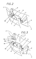
- Figure 2 is a partial perspective view of the top-box of the invention, which is shown with the half-shells secured in locked position;
- Figure 3 is a partial perspective view of the top-box of the invention, which is shown in opened position, that is, with the upper half-shell released from the lower half-shell; and
- Figure 4 is a partial view in side section of the lower half-shell of the top-box and the base plate on which it is attached, shown detached from each other.
-
- Making reference to Figures 1 and 2, a top-box for motorcycles in accordance with this invention includes a lower half-
shell 1 and an upper half-shell 2. The lower half-shell 1 is usually attached to a base plate (not shown in the figures) which is in turn fixed to the subframe of the motorcycle. In locked position the half-shells shell 2 can tilt in relation to the lower half-shell in order to be able to gain access to the objects stowed inside the top-box. - The half-
shells shell 2 being released from the lower half-shell 1 when they are in the locked position. - The locking means 3 include an
inserting element 4 attached to the lower half-shell 1 and areceiving element 5 attached to the upper half-shell. As can be appreciated, theinserting element 4 is a plate hinged onto the lower half-shell 1 provided with aprojection 4a on its upper part. Furthermore, thereceiving element 5 includes a plate provided with anorifice 5a (see Figure 3) into which theprojection 4a of theinserting element 4 is inserted. Saidprojection 4a extends in aprotuberance 4b (again, see Figure 3) which forms an inclined plane providing a slope designed to facilitate insertion of theprojection 4a into theorifice 5a, as will be described in detail below. - Also making reference to Figure 3, the aforesaid
inserting element 4 is hinged onto the lower half-shell 1 in such a way that it can move in the direction marked "S" in the figures, which is substantially perpendicular to the face of the lower half-shell 1. - The
inserting element 4 incorporateselastic means 7 that tend to keep theelement 4 in the position shown in Figures 1 and 2, that is, against thereceiving element 5. - The lower half-shell is provided with means for moving the
inserting element 4 to release the two half-shells lever 8 hinged onto the lower half-shell 1. Thislever 8 hasinterior projections 9 provided withorifices 10 into which oneend 11 of themetal rod 12, essentially having the form of an inverted "U", is inserted. Theopposite end 13 of therod 12 is left in contact with theinserting element 4. - The operation of the locking means is now explained with reference to Figures 2 and 3.
- In the locked position shown in Figure 2, the
lever 8 remains in substantially vertical position thanks to the action of a spring mounted on the interior part of theface 6, which keeps thelever 8 in the above-mentioned position (for reasons of clarity this spring is not shown in the figures). In this position, theprojection 4a of the insertingelement 4 is inserted into theorifice 5a of the receivingelement 5 of the upper half-shell 2, as can be clearly appreciated from Figure 2. - Making reference to Figure 3, in order to open the top-box the user must push the
lever 8 upwards as shown by the arrow M, overcoming the force of the spring mentioned above. When saidlever 8 is tilted, theinterior projection 9 causes rotation of theend 11 of therod 12. Theother end 13 also rotates and causes the insertingelement 4 to tilt forwards in the direction shown by the arrow S (Figure 3), overcoming the force of theelastic means 7 that oppose said tilting. The movement of the insertingelement 4 caused by the movement of thelever 8 results in theprojection 4a of the inserting element coming out of theorifice 5a of the receivingelement 5 and, as a consequence, means that the upper half-shell 2 can be released from the lower half-shell 1, as shown in Figure 3. - In order to close the top-box, starting from the position shown in Figure 3 the user must push the upper half-
shell 2, making it tilt towards the lower half-shell 1. This causes the receivingelement 5 to move towards the insertingelement 4 until the slope ofprotuberance 4b from the insertingelement 4 slides by contact on thelower surface 5b of the receivingelement 5. The sliding of theprotuberance 4b results in the insertingelement 4 tilting forward in the direction of the arrow S and overcoming the force of theelastic means 7. This continues until theprojection 4a is inserted into theorifice 5a of the receiving element, at which moment the inserting element returns to its initial position, that is, that determined by the aforesaidelastic means 7. At this point the top-box will be locked, with the half-shells - The description and the figures refer to locking means which include an inserting
element 4 and a receivingelement 5. It will nevertheless be understood that said locking means 3 can include a pair of inserting elements and a pair of receiving elements, arranged on either side of thelever 8. - On a top-box designed in accordance with the description, the means for moving said pair of inserting elements comprise a
lever 8 hinged onto the lower half-shell 1. Thislever 8 hasinterior projections 9 provided withorifices 10 into which are inserted theends 11 of the metal rods, while the opposite ends of said two rods are left in contact with each respective insertingelement 4. - The top-box of this invention makes allowance for the lower half-
shell 1 incorporating apower socket 14 in its lower part, as shown in Figure 4. Saidsocket 14 includes anelectrical contact element 15 that consists of a threaded terminal on the lower half-shell 1. Said terminal has a roundedhead 16 designed to make contact with a contact element. Said contact element includes twoflats 17 arranged parallel to each other and resting on acoupling element 18 of thebase plate 19 of the top-box. Thecoupling element 18 extends vertically and forms at its upper end ahorizontal projection 20 designed to fit into anorifice 21 of the lower half-shell 1. Theend 22 of thecontact element 17 is fixed onto thebase plate 19 by means of a fixingelement 23 and is connected to the power supply means of the motorcycle. - The top-box is fixed onto the motorcycle, and more specifically onto the subframe, by attaching the lower half-
shell 1 against theaforesaid base plate 19. As described, when the top-box is attached, that is, when the lower half-shell 1 is attached, onto thebase plate 19, the attachingelement 18 is inserted into theorifice 21 of said half-shell 1. When this happens the upper end of thecontact element 17, which is flexible to a certain extent, moves to the left as shown in Figure 4, when it slides on the surface of thehead 16 of theelectrical contact 15. The contact that exists between saidelement 17 and saidelectrical contact 15 allows electrical current to flow from the power supply means of the motorcycle to thecable 24, which is connected to theaforesaid contact 15. Thiscable 24 allows power supply to lighting means (not shown) situated on the upper part of the outside of the upper half-shell 2. - Independent of the object of this invention shall be all materials used in manufacturing of the elements making up the top-box for motorcycles described in this specification. Similarly, the shapes and dimensions of the box, and the technical characteristics of the locking means, the means for moving the inserting element and the means of lighting described may be as required for each specific utilisation. Moreover, all the accessory details that might be presented and the aforesaid technical characteristics may be replaced by other characteristics that are technically equivalent, as long as they do not affect its essential nature or depart from the scope defined by the appended claims.
Claims (6)
- Top-box for motorcycles that includes a lower half-shell (1) and an upper half-shell (2) that together form an interior chamber, the upper half-shell (2) being tiltable in relation to the lower half-shell (1) and said half-shells (1,2) having locking means (3) to prevent opening of the upper half-shell (2) with respect to the lower half-shell (1), said means including an inserting element (4) attached to the lower half-shell (1) and a receiving element (5) attached to the upper half-shell (2), characterised in that the inserting element (4) is hinged to the lower half-shell (1) in such a way that it can move in a direction (S) substantially perpendicular to the face (6) of the lower half-shell (1) to which said inserting element (4) is attached, said inserting element (4) having elastic means (7) for its insertion under pressure into the receiving element (5), the lower half-shell (1) being further provided with means (8, 12) for driving the inserting element (4) in order to release the two half-shells (1,2) from each other.
- Top-box as claimed in Claim 1, characterised in that the driving means (8,12) include a lever (8) hinged to the lower half-shell (1) and operatively connected with a rod (12) that acts on the inserting element (4).
- Top-box as claimed in either of Claims 1 or 2, characterised in that the locking means (3) include a pair of inserting elements (4) and a pair of receiving elements.
- Top-box as claimed in any of the previous claims, characterised in that the inserting element (4) is a plate hinged to the lower half-shell and provided with a projection (4a) on its top part, and in that the receiving element (5) includes a plate provided with an orifice (5a) in which the aforesaid projection (4a) is inserted, said projection (4a) of the inserting element (4) including a protuberance (4b) that forms an inclined plane providing a slope designed to facilitate insertion of the inserting element (4).
- Top-box as claimed in Claim 1, characterised in that the lower half-shell has a power socket supplied from the motorcycle.
- Top-box as claimed in Claim 5, characterised in that the upper part of the exterior of the upper half-shell is adapted for installing lighting means powered from the power socket of the lower half-shell.
Applications Claiming Priority (2)
| Application Number | Priority Date | Filing Date | Title |
|---|---|---|---|
| ES009801983A ES2154177B1 (en) | 1998-09-16 | 1998-09-16 | SUITCASE FOR MOTORCYCLES. |
| ES9801983 | 1998-09-16 |
Publications (3)
| Publication Number | Publication Date |
|---|---|
| EP0987172A2 true EP0987172A2 (en) | 2000-03-22 |
| EP0987172A3 EP0987172A3 (en) | 2001-03-21 |
| EP0987172B1 EP0987172B1 (en) | 2004-07-14 |
Family
ID=8305229
Family Applications (1)
| Application Number | Title | Priority Date | Filing Date |
|---|---|---|---|
| EP99500150A Expired - Lifetime EP0987172B1 (en) | 1998-09-16 | 1999-08-18 | Top-box for motorcycles |
Country Status (5)
| Country | Link |
|---|---|
| EP (1) | EP0987172B1 (en) |
| AT (1) | ATE270997T1 (en) |
| BR (1) | BR9904164A (en) |
| DE (1) | DE69918623D1 (en) |
| ES (1) | ES2154177B1 (en) |
Cited By (3)
| Publication number | Priority date | Publication date | Assignee | Title |
|---|---|---|---|---|
| EP1340672A1 (en) * | 2002-02-27 | 2003-09-03 | Nad, S.A. | Closing and securing mechanism for motorcycle cases and the like |
| CN102501925A (en) * | 2011-10-26 | 2012-06-20 | 广东广天机电工业研究院有限公司 | Containing box on scooter |
| JPWO2019131951A1 (en) * | 2017-12-28 | 2020-10-22 | 本田技研工業株式会社 | Storage box power supply structure for saddle-mounted vehicles |
Citations (4)
| Publication number | Priority date | Publication date | Assignee | Title |
|---|---|---|---|---|
| GB190810555A (en) * | 1908-05-15 | 1909-05-17 | Robert Marriner Painter | Improvements in or relating to Photographic Plate-holders. |
| DE2219522A1 (en) * | 1972-04-21 | 1973-10-31 | Agfa Gevaert Ag | CLOSURE FOR A POCKET, PREFERABLY READY BAG FOR CAMERAS |
| EP0709283A1 (en) * | 1994-10-31 | 1996-05-01 | Pedro Lucia Monforte | Mechanism for the closure and securing of cases for motorcycles and similar vehicles |
| EP0709282A1 (en) * | 1994-10-31 | 1996-05-01 | Pedro Lucia Monforte | Mechanism for the securing and closure of cases for motorcycles and similar vehicles |
Family Cites Families (6)
| Publication number | Priority date | Publication date | Assignee | Title |
|---|---|---|---|---|
| DE3032330C2 (en) * | 1980-08-27 | 1984-11-08 | Krauser Kraftfahrzeugzubehör Vertriebs-GmbH, 8905 Mering | Motorcycle case |
| IE851868L (en) * | 1985-07-25 | 1987-01-25 | Helene Francis Broderick | Pannier bags. |
| FR2621064B1 (en) * | 1987-09-25 | 1990-01-05 | Renault | FLAP LOCK FOR MOTOR VEHICLE |
| ES2027155A6 (en) * | 1990-12-10 | 1992-05-16 | Nad S A | Device for locking and removable coupling of storage compartments and cases on motorbikes and the like |
| DE4230996A1 (en) * | 1992-09-16 | 1994-03-17 | Winkhaus Fa August | Arrangement of a two-wheel lock on a vehicle frame and two-wheeled case for receiving the two-wheel lock |
| DE19511013A1 (en) * | 1995-03-25 | 1996-09-26 | Hepco & Becker Gmbh | Locking arrangement for motorcycle cases |
-
1998
- 1998-09-16 ES ES009801983A patent/ES2154177B1/en not_active Expired - Fee Related
-
1999
- 1999-08-18 EP EP99500150A patent/EP0987172B1/en not_active Expired - Lifetime
- 1999-08-18 AT AT99500150T patent/ATE270997T1/en not_active IP Right Cessation
- 1999-08-18 DE DE69918623T patent/DE69918623D1/en not_active Expired - Fee Related
- 1999-09-15 BR BR9904164-2A patent/BR9904164A/en not_active IP Right Cessation
Patent Citations (4)
| Publication number | Priority date | Publication date | Assignee | Title |
|---|---|---|---|---|
| GB190810555A (en) * | 1908-05-15 | 1909-05-17 | Robert Marriner Painter | Improvements in or relating to Photographic Plate-holders. |
| DE2219522A1 (en) * | 1972-04-21 | 1973-10-31 | Agfa Gevaert Ag | CLOSURE FOR A POCKET, PREFERABLY READY BAG FOR CAMERAS |
| EP0709283A1 (en) * | 1994-10-31 | 1996-05-01 | Pedro Lucia Monforte | Mechanism for the closure and securing of cases for motorcycles and similar vehicles |
| EP0709282A1 (en) * | 1994-10-31 | 1996-05-01 | Pedro Lucia Monforte | Mechanism for the securing and closure of cases for motorcycles and similar vehicles |
Cited By (5)
| Publication number | Priority date | Publication date | Assignee | Title |
|---|---|---|---|---|
| EP1340672A1 (en) * | 2002-02-27 | 2003-09-03 | Nad, S.A. | Closing and securing mechanism for motorcycle cases and the like |
| CN102501925A (en) * | 2011-10-26 | 2012-06-20 | 广东广天机电工业研究院有限公司 | Containing box on scooter |
| JPWO2019131951A1 (en) * | 2017-12-28 | 2020-10-22 | 本田技研工業株式会社 | Storage box power supply structure for saddle-mounted vehicles |
| EP3699070A4 (en) * | 2017-12-28 | 2020-12-02 | Honda Motor Co., Ltd. | Storage box power supply structure for saddled vehicle |
| US11554826B2 (en) | 2017-12-28 | 2023-01-17 | Honda Motor Co., Ltd. | Storage box power supply structure for saddled vehicle |
Also Published As
| Publication number | Publication date |
|---|---|
| ES2154177A1 (en) | 2001-03-16 |
| BR9904164A (en) | 2000-09-05 |
| ES2154177B1 (en) | 2001-10-16 |
| EP0987172B1 (en) | 2004-07-14 |
| DE69918623D1 (en) | 2004-08-19 |
| ATE270997T1 (en) | 2004-07-15 |
| EP0987172A3 (en) | 2001-03-21 |
Similar Documents
| Publication | Publication Date | Title |
|---|---|---|
| US5618052A (en) | Bicycle attachment | |
| US4282631A (en) | Tiltable roller assembly | |
| CA2127342C (en) | Pocketknife with blade locking mechanism and push-button type blade release | |
| CA2091599C (en) | Battery case attaching unit including housing and battery case and stopper for securing battery case in housing | |
| US5954161A (en) | Braking structure for rehabilitation trolley | |
| FR2525907A1 (en) | ANCHOR FOR CLOSING A SEAT BELT | |
| KR100249364B1 (en) | Hinge for refrigerator door | |
| US4722032A (en) | Vehicle tail lamp assembly | |
| US5152496A (en) | Lock structure for vehicle mounted type electronic equipment | |
| US20020154500A1 (en) | Flashlight securement systems | |
| FR2530205A1 (en) | DOOR MIRROR DEVICE FOR MOTOR VEHICLES | |
| EP0987172B1 (en) | Top-box for motorcycles | |
| FR2861676A1 (en) | BATTERY RETENTION MECHANISM IN AN INDUSTRIAL VEHICLE | |
| EP3665348B1 (en) | A vehicular door handle assembly and method for assembling the same | |
| US5926545A (en) | Battery holder | |
| JP5016159B2 (en) | Vehicle cabriolet structure with removable side members | |
| US5438685A (en) | Vehicular adapter pocket and handle assembly | |
| JP2560562Y2 (en) | Control unit detachable structure | |
| US20080207086A1 (en) | Children's toy, particularly children's vehicle with bucket | |
| ES1029301U (en) | Mechanism for the closure and securing of cases for motorcycles and similar vehicles | |
| KR960003854Y1 (en) | Opening device for motor-cycle tools carrier | |
| FR2859953A1 (en) | Detachable seat for vehicle, has front locking device with prong that supports base on floor pan of vehicle when seat pivots towards normal usage position and is elastically pushed to one position in absence of external support on base | |
| KR920006036Y1 (en) | Control box tilting apparatus in excavator | |
| JPH0513644Y2 (en) | ||
| FR2804338A1 (en) | SKI MOUNTING WITH REMOVABLE BRAKE |
Legal Events
| Date | Code | Title | Description |
|---|---|---|---|
| PUAI | Public reference made under article 153(3) epc to a published international application that has entered the european phase |
Free format text: ORIGINAL CODE: 0009012 |
|
| AK | Designated contracting states |
Kind code of ref document: A2 Designated state(s): AT BE CH CY DE DK ES FI FR GB GR IE IT LI LU MC NL PT SE |
|
| AX | Request for extension of the european patent |
Free format text: AL;LT;LV;MK;RO;SI |
|
| RIC1 | Information provided on ipc code assigned before grant |
Free format text: 7B 62J 9/00 A, 7B 65D 43/22 B, 7A 45C 13/10 B |
|
| PUAL | Search report despatched |
Free format text: ORIGINAL CODE: 0009013 |
|
| AK | Designated contracting states |
Kind code of ref document: A3 Designated state(s): AT BE CH CY DE DK ES FI FR GB GR IE IT LI LU MC NL PT SE |
|
| AX | Request for extension of the european patent |
Free format text: AL;LT;LV;MK;RO;SI |
|
| 17P | Request for examination filed |
Effective date: 20010907 |
|
| AKX | Designation fees paid |
Free format text: AT BE CH CY DE DK ES FI FR GB GR IE IT LI LU MC NL PT SE |
|
| GRAP | Despatch of communication of intention to grant a patent |
Free format text: ORIGINAL CODE: EPIDOSNIGR1 |
|
| GRAS | Grant fee paid |
Free format text: ORIGINAL CODE: EPIDOSNIGR3 |
|
| GRAA | (expected) grant |
Free format text: ORIGINAL CODE: 0009210 |
|
| AK | Designated contracting states |
Kind code of ref document: B1 Designated state(s): AT BE CH CY DE DK ES FI FR GB GR IE IT LI LU MC NL PT SE |
|
| PG25 | Lapsed in a contracting state [announced via postgrant information from national office to epo] |
Ref country code: NL Free format text: LAPSE BECAUSE OF FAILURE TO SUBMIT A TRANSLATION OF THE DESCRIPTION OR TO PAY THE FEE WITHIN THE PRESCRIBED TIME-LIMIT Effective date: 20040714 Ref country code: LI Free format text: LAPSE BECAUSE OF FAILURE TO SUBMIT A TRANSLATION OF THE DESCRIPTION OR TO PAY THE FEE WITHIN THE PRESCRIBED TIME-LIMIT Effective date: 20040714 Ref country code: IT Free format text: LAPSE BECAUSE OF FAILURE TO SUBMIT A TRANSLATION OF THE DESCRIPTION OR TO PAY THE FEE WITHIN THE PRESCRIBED TIME-LIMIT;WARNING: LAPSES OF ITALIAN PATENTS WITH EFFECTIVE DATE BEFORE 2007 MAY HAVE OCCURRED AT ANY TIME BEFORE 2007. THE CORRECT EFFECTIVE DATE MAY BE DIFFERENT FROM THE ONE RECORDED. Effective date: 20040714 Ref country code: FR Free format text: LAPSE BECAUSE OF FAILURE TO SUBMIT A TRANSLATION OF THE DESCRIPTION OR TO PAY THE FEE WITHIN THE PRESCRIBED TIME-LIMIT Effective date: 20040714 Ref country code: FI Free format text: LAPSE BECAUSE OF FAILURE TO SUBMIT A TRANSLATION OF THE DESCRIPTION OR TO PAY THE FEE WITHIN THE PRESCRIBED TIME-LIMIT Effective date: 20040714 Ref country code: CY Free format text: LAPSE BECAUSE OF FAILURE TO SUBMIT A TRANSLATION OF THE DESCRIPTION OR TO PAY THE FEE WITHIN THE PRESCRIBED TIME-LIMIT Effective date: 20040714 Ref country code: CH Free format text: LAPSE BECAUSE OF FAILURE TO SUBMIT A TRANSLATION OF THE DESCRIPTION OR TO PAY THE FEE WITHIN THE PRESCRIBED TIME-LIMIT Effective date: 20040714 Ref country code: BE Free format text: LAPSE BECAUSE OF FAILURE TO SUBMIT A TRANSLATION OF THE DESCRIPTION OR TO PAY THE FEE WITHIN THE PRESCRIBED TIME-LIMIT Effective date: 20040714 Ref country code: AT Free format text: LAPSE BECAUSE OF FAILURE TO SUBMIT A TRANSLATION OF THE DESCRIPTION OR TO PAY THE FEE WITHIN THE PRESCRIBED TIME-LIMIT Effective date: 20040714 |
|
| REG | Reference to a national code |
Ref country code: GB Ref legal event code: FG4D |
|
| REG | Reference to a national code |
Ref country code: CH Ref legal event code: EP |
|
| PG25 | Lapsed in a contracting state [announced via postgrant information from national office to epo] |
Ref country code: LU Free format text: LAPSE BECAUSE OF NON-PAYMENT OF DUE FEES Effective date: 20040818 Ref country code: IE Free format text: LAPSE BECAUSE OF NON-PAYMENT OF DUE FEES Effective date: 20040818 |
|
| REF | Corresponds to: |
Ref document number: 69918623 Country of ref document: DE Date of ref document: 20040819 Kind code of ref document: P |
|
| REG | Reference to a national code |
Ref country code: IE Ref legal event code: FG4D |
|
| PG25 | Lapsed in a contracting state [announced via postgrant information from national office to epo] |
Ref country code: MC Free format text: LAPSE BECAUSE OF NON-PAYMENT OF DUE FEES Effective date: 20040831 |
|
| PG25 | Lapsed in a contracting state [announced via postgrant information from national office to epo] |
Ref country code: SE Free format text: LAPSE BECAUSE OF FAILURE TO SUBMIT A TRANSLATION OF THE DESCRIPTION OR TO PAY THE FEE WITHIN THE PRESCRIBED TIME-LIMIT Effective date: 20041014 Ref country code: GR Free format text: LAPSE BECAUSE OF FAILURE TO SUBMIT A TRANSLATION OF THE DESCRIPTION OR TO PAY THE FEE WITHIN THE PRESCRIBED TIME-LIMIT Effective date: 20041014 Ref country code: GB Free format text: LAPSE BECAUSE OF NON-PAYMENT OF DUE FEES Effective date: 20041014 Ref country code: DK Free format text: LAPSE BECAUSE OF FAILURE TO SUBMIT A TRANSLATION OF THE DESCRIPTION OR TO PAY THE FEE WITHIN THE PRESCRIBED TIME-LIMIT Effective date: 20041014 |
|
| PG25 | Lapsed in a contracting state [announced via postgrant information from national office to epo] |
Ref country code: ES Free format text: LAPSE BECAUSE OF FAILURE TO SUBMIT A TRANSLATION OF THE DESCRIPTION OR TO PAY THE FEE WITHIN THE PRESCRIBED TIME-LIMIT Effective date: 20041025 |
|
| NLV1 | Nl: lapsed or annulled due to failure to fulfill the requirements of art. 29p and 29m of the patents act | ||
| REG | Reference to a national code |
Ref country code: CH Ref legal event code: PL |
|
| PG25 | Lapsed in a contracting state [announced via postgrant information from national office to epo] |
Ref country code: DE Free format text: LAPSE BECAUSE OF NON-PAYMENT OF DUE FEES Effective date: 20050301 |
|
| PLBE | No opposition filed within time limit |
Free format text: ORIGINAL CODE: 0009261 |
|
| STAA | Information on the status of an ep patent application or granted ep patent |
Free format text: STATUS: NO OPPOSITION FILED WITHIN TIME LIMIT |
|
| GBPC | Gb: european patent ceased through non-payment of renewal fee |
Effective date: 20041014 |
|
| REG | Reference to a national code |
Ref country code: IE Ref legal event code: MM4A |
|
| 26N | No opposition filed |
Effective date: 20050415 |
|
| EN | Fr: translation not filed | ||
| PG25 | Lapsed in a contracting state [announced via postgrant information from national office to epo] |
Ref country code: PT Free format text: LAPSE BECAUSE OF NON-PAYMENT OF DUE FEES Effective date: 20041214 |