EP0986733B1 - Robust accurate gps time reference for space application - Google Patents
Robust accurate gps time reference for space application Download PDFInfo
- Publication number
- EP0986733B1 EP0986733B1 EP99914896A EP99914896A EP0986733B1 EP 0986733 B1 EP0986733 B1 EP 0986733B1 EP 99914896 A EP99914896 A EP 99914896A EP 99914896 A EP99914896 A EP 99914896A EP 0986733 B1 EP0986733 B1 EP 0986733B1
- Authority
- EP
- European Patent Office
- Prior art keywords
- signals
- gps
- unit
- time
- spacecraft
- Prior art date
- Legal status (The legal status is an assumption and is not a legal conclusion. Google has not performed a legal analysis and makes no representation as to the accuracy of the status listed.)
- Expired - Lifetime
Links
Images


Classifications
-
- G—PHYSICS
- G01—MEASURING; TESTING
- G01S—RADIO DIRECTION-FINDING; RADIO NAVIGATION; DETERMINING DISTANCE OR VELOCITY BY USE OF RADIO WAVES; LOCATING OR PRESENCE-DETECTING BY USE OF THE REFLECTION OR RERADIATION OF RADIO WAVES; ANALOGOUS ARRANGEMENTS USING OTHER WAVES
- G01S19/00—Satellite radio beacon positioning systems; Determining position, velocity or attitude using signals transmitted by such systems
- G01S19/38—Determining a navigation solution using signals transmitted by a satellite radio beacon positioning system
- G01S19/39—Determining a navigation solution using signals transmitted by a satellite radio beacon positioning system the satellite radio beacon positioning system transmitting time-stamped messages, e.g. GPS [Global Positioning System], GLONASS [Global Orbiting Navigation Satellite System] or GALILEO
- G01S19/42—Determining position
-
- G—PHYSICS
- G04—HOROLOGY
- G04G—ELECTRONIC TIME-PIECES
- G04G7/00—Synchronisation
- G04G7/02—Synchronisation by radio
Definitions
- the present invention relates to space vehicle navigation and control and more particularly to a method and apparatus for providing an accurate Global Positioning System (GPS) time reference for spacecraft such as Low Earth Orbit (LEO) satellites.
- GPS Global Positioning System
- LEO Low Earth Orbit
- Satellites and other spacecraft require a time reference for controlling their navigation and orientation and coordinating their operations with other devices with which they interact.
- a common source of a time reference is the GPS which provides signals from which the local satellite clock bias can be determined to generate an accurate time reference.
- receivers for detecting and using GPS signals require the pick up of signals from a number of GPS satellites, for example, the Three Axis Navigation System (TANS) Vector receiver for satellites, available from TRIMBLE NAVIGATION, of Sunnyvale, CA, requires 4 GPS satellites to be in the view of the receiver in order to provide the receiver clock bias to generate the time reference. If there are less than 4 such satellites in view, hen the clock bias solution is held fixed, which results in large errors in the time reference.
- TANS Three Axis Navigation System
- US 5,490,076 to Rawicz et al describes a system using an anchor fixed in place on the earth. Communications are made between the anchor and a constellation of autonavigating satellites, and the anchor implements a filtering algorithm to arrive at solution for the satellite positions. The system updates satellites positions rapidly. Each satellite includes its own Kalman filter and receives cross-link data from other satellites.
- apparatus for providing an accurate Global Positioning System (GPS) time reference for a spacecraft comprising: a real-time navigation Kalman filter means, in said spacecraft, which processes directly measured GPS signals from GPS satellite vehicles; receiver means, in said spacecraft, for producing a time reference estimation for said spacecraft; characterised in that the Kalman filter includes a dynamic model of the motion of the spacecraft for calculating the receiver clock bias signal whether or not fewer than four GPS signals are received; and the Kalman filter outputs the receiver clock bias signal to the receiver means whether or not fewer than four GPS signals are received.
- GPS Global Positioning System
- the present invention is directed to obtaining a receiver clock bias signal for a spacecraft in motion to generate an accurate time reference.
- the invention uses a real-time navigation Kalman filter solution of the receiver clock bias to provide a GPS time reference even when there are less than 4 GPS satellites within the view of the receiver in the spacecraft.
- the real-time navigation Kalman filter in the spacecraft is adapted to provide an accurate solution of the clock bias even when there are outages of less than 4 GPS satellites in view by the receiver, by means of a system which uses the knowledge of the dynamic motion of the satellite in conjunction with GPS signals for a robust estimation of time.
- the system provides an accurate GPS time reference for a receiver in dynamic motion, even when less than 4 GPS satellites are in view, by transferring timing information from an atomic reference standard (GPS) to a spacecraft in motion by directly measuring the GPS signal and without depending upon the tracking of multiple GPS satellites or a static receiver.
- GPS atomic reference standard
- the invention may be implemented in current aerospace qualified GPS receivers, e.g., the "GPS TENSORTM" produced by the assignee of the present application, and known orbital dynamics are used to predict receiver position which aids in the transfer of the GPS time.
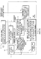
- Figure 1 is a schematic diagram of the conventional navigation Kalman filter.
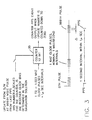
- FIG 2 is a block diagram of a system illustrating how the filter clock bias solution of the navigation Kalman filter of Figure 1 can be used for a pulse-per-second (PPS) time reference in accordance with the invention.
- PPS pulse-per-second
- Figure 3 illustrates how the PPS is generated from the clock bias solution obtained with the system of Figure 2.
- Figure 4 illustrates a matrix equation for one embodiment of the Measurement Model unit of the navigation Kalman filter of Figure 1 in accordance with the present invention.
- FIG 5 illustrates matrix equations for one embodiment of the Measurement Update unit and the Time Update unit of the navigation Kalman filter of Figure 1 in accordance with the present invention.
- the present invention involves the use of a real-time navigation Kalman filter solution of the receiver clock bias to provide a GPS time reference for a spacecraft or satellite in motion.
- the real-time navigation Kalman filter in the spacecraft can be used to provide an accurate solution of the clock bias even when there are less than four GPS satellites in the view of the receiver.
- An example of a current advanced aerospace qualified GPS receiver in which the present invention may be implemented is the "GPS TENSORTM" (TM of the assignee of the present application), such as disclosed in an article by present co-inventor R. A. FULLER, and others, entitled “Spacecraft Guidance and Control with GPS Tensor", presented at the 19th Annual AAS Guidance and Control Conference, Feb.
- GPS TENSORTM generates navigation position/velocity data, precision timing signals, and 3 axes of spacecraft attitude, utilizing 9 channels, and is particularly suited for use with the "GLOBALSTAR" (TM of Globalstar, Inc.) communication satellite constellation presently in the process of being implemented.
- the operation of this receiver starts with coded RF signals from the GPS Satellite Vehicles (SVs) in a constellation flying at about 20,000 km, half synchronous altitude.
- the first step is to measure "pseudo-ranges" between the spacecraft or satellite carrying the receiver and the GPS SVs.
- the pseudo-range is the time delay or "distance” between the time a signal is sent from a GPS SV and the time of its receipt by the spacecraft receiver plus the clock bias offset of the receiver clock, or in other words, the true geometrical distance between the SV and receiver at the time of signal transmission plus the effect of the receiver clock bias.
- the operation of the invention requires that pseudo-range signals be available and in progress and preferably that they be received by multiple antennas, although in actuality the navigation function only requires one antenna.
- the invention may be implemented in any spacecraft that can usefully receive GPS signals, typically LEO spacecraft with altitudes below about 20,000 km.
- FIG. 1 is a block diagram of the elements and functions of a conventional navigation Kalman filter (KF) in a satellite vehicle (SV)
- KF navigation Kalman filter
- SV satellite vehicle
- the beginning of the process involves initializing an index k to 0, and the parameters ⁇ (t k ), M(t k ), Q, and ⁇ ( ⁇ ), in initializing unit 5 of the filter.
- t k is the time index and the other parameters are identified as follows:
- the resulting ⁇ and M signals are provided as an input to Measurement Model (MM) unit 1, along with time indexing, (t k ), signals from incrementing unit 7, for inclusion in a computation made in the MM unit 1 ( Figure 4).
- Another input signal to the MM unit 1 is produced by first obtaining n pseudo-range measurements ⁇ and the corresponding ephemeris data of the GPS satellites used as the sources in unit 9, and providing this information to a conversion unit 2 which converts the GPS ephemeris data into Earth-Centered-Earth-Fixed (ECEF) position and velocity indicative signals.
- ECEF is the reference coordinate system in which the GPS ephemeris is reported.
- the ECEF position and velocity indicative signals are then converted to signals x g of another reference coordinate system, i.e., Earth-Centered-Inertial (ECI) signals, in converting unit 3 and input to the MM unit 1.
- the MM unit 1 functions to compute ( Figure 4), using the incremented ⁇ signal and the ECI signals x g , a predicted measurement and the corresponding partial derivatives from the measurement model, and outputs signals indicative thereof, h, H, to a Measurement Update (MU) unit 4 ( Figure 5).
- MU Measurement Update
- the MU unit 4 In addition to the h, H signal input, the MU unit 4 also receives an incremented z input of n pseudo-range measurements ⁇ used as the sources, from unit 9, and computes a current estimate of the ECI position, velocity, and clock bias of the receiver from the measurement update equations.
- the MU unit 4 after each measurement, uses time indexed covariance matrix M(t k ) to generate a new updated estimate ⁇ of position, velocity, and clock bias parameters, in this case it is 9 states, as well as a new covariance matrix P, and provides output signals indicative of ⁇ and P, to a Time Update (TU) unit 6 ( Figure 5) and a transform (Tr) unit 8.
- the TU unit 6 uses the signals, ⁇ , P, input from the MU unit 4 to predict the states at the next time step and obtain the corresponding state transition matrix by integrating, respectively, the dynamic equations and their derivatives, to the degree of accuracy required.
- the Tr unit 8 transforms ECI position and velocity signals, input from the MU unit 4, to orbital elements, for computation of the mean elements, and outputs signals indicative of position, velocity, and orbital elements, both osculating and mean. These output signals also include the filter clock bias solution.
- FIG 2 shows a block diagram of a system for navigation solution flow, such as may be implemented in the GPS TENSOR", and illustrates how the filter clock bias solution can be used for the Pulse-Per-Second (PPS) time reference.
- the Navigation Filter (NF) unit 14 is the navigation Kalman filter (KF) described above with respect to Figure 1, and the receiver clock bias solution of the NF unit 14 can be used for resetting the integer clock bias in Integer Clock Bias Reset unit 13 and/or for generating PPS pulses in PPS Generation unit 16.
- KF navigation Kalman filter
- a Code Delay Lock Loop (DLL) unit 10 is provided to measure fractional millisecond parts of the pseudo-ranges, and the integer number of milliseconds in a pseudo-range is initially calculated upon SV signal acquisition. Both the pseudo-range and clock bias values are divided into terms comprising integer millisecond distances, e. g., 300 km, plus a fractional millisecond segment.
- PRMI unit 11 also receives an integer clock bias signal, that is similarly reset and rolled over at an Integer Clock Bias Reset (ICBR) unit 13, from the bias calculated in either the Standard Position Service (SPS) unit 12 or the Navigation Filter (NF) unit 14.
- ICBR Integer Clock Bias Reset
- SPS Standard Position Service
- NF Navigation Filter
- the millisecond integer corrected pseudo-range signals are input to the SPS unit 12 and the NF unit 14 at different rates, timed by sample switches 18, 19.
- the sample time of the SPS unit 12 is 0.5 seconds, and the sample time of the NF unit 14 is selectable with a default time of 30 seconds.
- the initialization of the NF unit 14 is preceded by 120 SPS solutions.
- the NF unit (14) computations have a bias estimate independent from the SPS solution. So if the adjustment is made using one solution, the bias of the other solution is incremented at the same time to stay consistent with the adjusted pseudo-range measurements.
- the GPS time reference is the standard throughout the network for communications systems such as the GLOBALSTAR satellites.
- the SPS unit 12 numerically solves for the 4 unknowns, i.e., the x-y-z positions and the clock bias b, using 4 pseudo-range measurements.
- This Service (SPS) 12 is subject to position calculation outages and without these 4 measurements no SPS solution is possible. Then a separate Clock Bias Propagator unit 17 may be utilized.
- An alternate navigation solution involving the Navigation Filter (14) algorithm uses individual pseudo-range measurements to adjust a continuous running dynamic model of the 4 system position parameters, x-y-z, and clock bias b, and their derivatives.
- the NF unit 14 can use up to all 9 measurement channels available in the GPS TENSORTM. It also will generate an estimate of the position parameters, even in the event of short term absences of new pseudo-range inputs, based on dynamic extrapolation of the preceding operation.
- the NF unit (14) operation is first initialized with the SPS solution. To ensure that the SPS solution is stable, 120 such solutions are generated before initializing the NF unit 14.
- the NF unit 14 estimates 9 states, i.e., 3 position states, 3 velocity states, and receiver clock bias, bias rate, and bias acceleration.
- the filter typically converges within two orbital periods of the satellite containing the GPS receiver.
- the NF unit (14) solution is more accurate than the SPS unit (12) solution since it continually averages more data.
- the NF unit solution is also more robust since it doesn't suffer outages when there are less than 4 SVs available for processing.
- the interaction of these two solutions in conditioning the pseudo-range input data may be dealt with by the melding of the integer millisecond roll-over from the Code Delay Lock Loop (DLL) unit 10 with the millisecond resets.
- DLL Code Delay Lock Loop
- the PPS output at unit 16 is more robust with the NF solution than with the SPS solution since, as noted, the latter is more susceptible to outages.
- the precision timing signal of the PPS output is critical. There are separate output pins for these pulses which are produced at a 1 second interval accurate to a microsecond.
- the entire network of GLOBALSTAR communication frequencies are locked onto the "universal" GPS Time as detected and regenerated by the GPS TENSORTM.
- the generation of the PPS signal is based on the clock bias parameter of the navigation calculations.
- the GPS TENSORTM operates such that the default selection of the NF calculated clock bias is used for PPS generation.
- FIG 3 illustrates the pulses per second (PPS) mechanization in the PPS Generation unit 16 of Figure 2. It is the mechanism that generates a time reference based on the GPS system.
- One of its inputs is the receiver clock bias which in turn is produced either from the NF unit (14) solution or the SPS unit (16) solution, both of which use measurements from GPS satellites that are in the view of the receiver.
- a clock bias signal input, ⁇ , to a 12-bit counter 20 is updated from software at the 999 th msec pulse from the last PPS pulse as seen in the lower part of Figure 2 which shows 1 kHz clock pulses, at nominal 1 millisecond intervals. This number ⁇ , scaled for the counter 20, is the receiver clock bias determined in the Navigation solution.
- Another input constitutes pulses from a 1.023 MHz clock at roughly 1 ⁇ sec intervals.
- the counter (20) produces a PPS event output when the update number is counted down to zero. While PPS generation works with the SPS solution, due to the significant degradation of its accuracy when less than 4 satellites are in view, the NF solution is preferable as it can be accurately maintained even during outages so that the resulting PPS also remains accurate.
- Figure 4 illustrates a matrix equation for one embodiment of the MM unit 1 of the navigation Kalman filter of Figure 1 in accordance with the present invention, wherein the noise on the pseudorange measurements, ⁇ , is modeled with a zero mean normal distribution, N, and with a covariance matrix, V, which is assumed to be diagonal as indicated by the identity matrix, In, of dimension n.
- the navigation filter may consist of 9 states that include the 3 position coordinates (x, y, z), their rates, the clock bias, b, and its rate and acceleration.
- Figure 5 illustrates matrix equations for one embodiment of the Measurement Update unit 4 and the Time Update unit 6 of the navigation Kalman filter of Figure 1 in accordance with the present invention, wherein ⁇ is a dummy time variable in the integrals, ⁇ is the state transition matrix, W d is the discreet state noise covariance matrix, F is the Jacobian of the state derivative function f, ⁇ is the transition matrix from the state noise to all the states, and Q is the spectral density matrix of the state noise.
- a real-time navigation Kalman filter solution of the receiver clock bias can be used to provide a GPS time reference even when there are outages of less than 4 satellites in view by the receiver, and thus this approach provides a more robust source of receiver clock bias solutions.
- the prior art only solves for precise timing when 1) 4 satellites are in view by the receiver in dynamic motion, and 2) one satellite is in view by a static receiver.
- the invention uses the knowledge of the dynamic motion of the satellite in conjunction with GPS signals for robust estimation of time.
- GPS atomic reference standard
Landscapes
- Engineering & Computer Science (AREA)
- Radar, Positioning & Navigation (AREA)
- Remote Sensing (AREA)
- Physics & Mathematics (AREA)
- General Physics & Mathematics (AREA)
- Computer Networks & Wireless Communication (AREA)
- Position Fixing By Use Of Radio Waves (AREA)
Abstract
Description
satellites in view by the receiver, by means of a system which uses the knowledge of the dynamic motion of the satellite in conjunction with GPS signals for a robust estimation of time. The system provides an accurate GPS time reference for a receiver in dynamic motion, even when less than 4 GPS satellites are in view, by transferring timing information from an atomic reference standard (GPS) to a spacecraft in motion by directly measuring the GPS signal and without depending upon the tracking of multiple GPS satellites or a static receiver. The invention may be implemented in current aerospace qualified GPS receivers, e.g., the "GPS TENSOR™" produced by the assignee of the present application, and known orbital dynamics are used to predict receiver position which aids in the transfer of the GPS time.
Claims (8)
- Apparatus for providing an accurate Global Positioning System (GPS) time reference for a spacecraft, comprising:characterised in that the Kalman filter includes a dynamic model of the motion of the spacecraft for calculating the receiver clock bias signal whether or not fewer than four GPS signals are received; and the Kalman filter outputs the receiver clock bias signal to the receiver means whether or not fewer than four GPS signals are received.a real-time navigation Kalman filter means, in said spacecraft, which processes directly measured GPS signals from GPS satellite vehicles;receiver means, in said spacecraft, for producing a time reference estimation for said spacecraft;
- Apparatus as claim 1 wherein said GPS satellite vehicles comprise less than four.
- A method for providing an accurate Global Positioning System (GPS) time reference for a spacecraft, comprising the steps of;
directly measuring GPS signals from GPS satellite vehicles;
processing the measured GPS signals in a real-time navigation Kalman filter means, in said spacecraft;
producing, in a said spacecraft, a time reference estimation for said spacecraft;
Characterised by calculating in a dynamic model of the motion of the spacecraft in the Kalman filter the receiver clock bias signal whether or not fewer than four GPS signals are received; and outputting the receiver clock bias signal to the receiver means whether or not fewer than four GPS signals are received. - A method as claim 3 wherein said GPS satellite vehicles comprise less than four.
- Apparatus according to claim 1 further comprising:a measurement model (MM) unit in said Kalman filter;means for initializing a time index tk to 0, and χ (t-k), M (tk), Q, and σ(ρ) and providing χ, M signals as an input to said MM unit;means for providing incrementing time index, tk, signals as an input to said MM unit;means for obtaining n pseudo-range measurements and the corresponding ephemeris data of the GPS satellites used as the sources for said measurements and emphemeris data information, and producing a signal z with this information;means for converting the GPS ephemeris data into Earth-Centered-Earth-Fixed (ECEF) position and velocity indicative signals, where ECEF is the reference coordinate system in which the GPS ephemeris is reported;means for converting the ECEF position and velocity indicative signals to another reference coordinate system, Earth-Centered-Inertial (ECI) signals, xg, and inputting said xg signals to the MM unit;a measurement update (MU) unit;a time update (TU) unit;a transform (Tr) unit;means, using the incremented χ and M signals, said incremented time index, tk, signals, and the ECI signals xg, for computing a predicted measurement and the corresponding partial derivatives from the measurement model, and outputting signals indicative thereof, h, H, to said MU unit;means for inputting an incremented signal z to the MU unit;means, in said MU unit, for using signals h, H, and z to compute a current estimate of the ECI position, velocity, and clock of the SV from the measurement update equations, and providing resulting output signals, χ, P, from the MU unit to said time update (TU) unit and said transform (Tr) unit;means, in said TU unit, for using the signals, χ, P, to predict the states at the next time step and to obtain the corresponding state transition matrix by integrating, respectively, the dynamic equations and their derivatives, to the degree of accuracy required;means, in said Tr unit, for transforming the signals, χ, to orbital elements, and computing the mean elements, and outputting signals indicative of position, velocity, and orbital elements, both osculating and mean, which output signals provide the filter clock bias solution; andmeans, responsive to said signals indicative of position, velocity, and orbital elements, both osculating and mean, for using said filter clock bias solution to obtain an accurate Global Positioning System (GPS) time reference.
- Apparatus as claim 5 wherein said GPS satellites comprise less than four.
- A method according to claim 3 for providing an accurate Global Positioning System (GPS) time reference for an Earth satellite using a navigation Kalman filter that receives GPS signals from GPS satellite sources, comprising the steps of:wherein the step of directly measuring GPS signals includes obtaining information including n pseudo-range measurements and the corresponding ephemeris data of the GPS satellites used as the sources, and producing a signal z with said informationinitializing an index k to 0, and χ (tk), M (tk), Q, and σ(ρ) parameters and providing χ, M signals as an input to a measurement model (MM) unit in the filter containing a measurement model with partial derivatives;providing incremented time index, tk, signals as an input to said MM unit;converting the GPS ephemeris data into Earth-Centered-Earth-Fixed (ECEF) position and velocity indicative signals, where ECEF is the reference coordinate system in which the GPS ephemeris data is reported;converting said ECEF position and velocity indicative signals to another reference coordinate system, Earth-Centered-Inertial (ECI) signals, xg, and inputting said xg signals to said MM unit;computing, using incremented χ and M signals, said incremented time index, tk, signals and the ECI signals xg, a predicted measurement and the corresponding partial derivatives from the measurement model, and outputting signals indicative thereof, h, H, to a measurement update (MU) unit 4 with measurement update equations;inputting an incremented signal z to the MU unit and using signals h, H, and z to compute a current estimate of the ECI position, velocity, and clock of the SV from the measurement update equations, and providing resulting output signals, χ, P, from the MU unit to a time update (TU) unit and a transform (Tr) unit;using the signals, χ, P, in the TU unit to predict the states at the next time step and to obtain the corresponding state transition matrix by integrating, respectively, the dynamic equations and their derivatives, to the degree of accuracy required;using the Tr unit to transform the signals, χ to orbital elements, and computing the mean elements, and outputting signals indicative of position, velocity, and orbital elements, both osculating and mean, which output signals provide the filter clock bias solution; and
and the step of producing a time reference estimation includes using said filter clock bias solution to obtain an accurate Global Positioning System (GPS) time reference. - A method as claim 7 wherein said GPS satellites comprise less than four.
Applications Claiming Priority (5)
| Application Number | Priority Date | Filing Date | Title |
|---|---|---|---|
| US8021398P | 1998-03-31 | 1998-03-31 | |
| US80213P | 1998-03-31 | ||
| US256712 | 1999-02-24 | ||
| US09/256,712 US6266584B1 (en) | 1998-03-31 | 1999-02-24 | Robust autonomous GPS time reference for space application |
| PCT/US1999/005178 WO1999050618A1 (en) | 1998-03-31 | 1999-03-08 | Robust accurate gps time reference for space application |
Publications (3)
| Publication Number | Publication Date |
|---|---|
| EP0986733A1 EP0986733A1 (en) | 2000-03-22 |
| EP0986733A4 EP0986733A4 (en) | 2000-07-05 |
| EP0986733B1 true EP0986733B1 (en) | 2002-06-12 |
Family
ID=26763223
Family Applications (1)
| Application Number | Title | Priority Date | Filing Date |
|---|---|---|---|
| EP99914896A Expired - Lifetime EP0986733B1 (en) | 1998-03-31 | 1999-03-08 | Robust accurate gps time reference for space application |
Country Status (4)
| Country | Link |
|---|---|
| US (1) | US6266584B1 (en) |
| EP (1) | EP0986733B1 (en) |
| DE (1) | DE69901766T2 (en) |
| WO (1) | WO1999050618A1 (en) |
Cited By (1)
| Publication number | Priority date | Publication date | Assignee | Title |
|---|---|---|---|---|
| CN106202877A (en) * | 2016-06-28 | 2016-12-07 | 桂林电子科技大学 | The error correction principle of GPS IIR M type satellite supper-fast clock correction forecast |
Families Citing this family (24)
| Publication number | Priority date | Publication date | Assignee | Title |
|---|---|---|---|---|
| DE19907235A1 (en) | 1999-02-19 | 2000-09-14 | Daimler Chrysler Ag | GPS navigation system for space applications |
| US6608589B1 (en) * | 1999-04-21 | 2003-08-19 | The Johns Hopkins University | Autonomous satellite navigation system |
| US6411892B1 (en) * | 2000-07-13 | 2002-06-25 | Global Locate, Inc. | Method and apparatus for locating mobile receivers using a wide area reference network for propagating ephemeris |
| FR2814232B1 (en) * | 2000-09-15 | 2002-11-29 | Centre Nat Etd Spatiales | PROCESS FOR CALCULATING INSTANTANEOUS CHARACTERISTICS IN ORBIT EQUIPPED WITH A GNSS RECEIVER |
| US6682019B2 (en) * | 2002-04-04 | 2004-01-27 | Honeywell International Inc. | Minimum energy wheel configurations for energy storage and attitude control |
| US7844346B2 (en) * | 2002-05-23 | 2010-11-30 | Biocontrol Medical Ltd. | Electrode assembly for nerve control |
| US6958953B2 (en) * | 2003-05-13 | 2005-10-25 | International Business Machines Corporation | Real time clock circuit having an internal clock generator |
| FR2892828A1 (en) * | 2005-11-02 | 2007-05-04 | Alcatel Sa | Satellite position determining method, for e.g. global positioning system, involves determining forecasts of satellite positions based on satellite orbits computed by converting data items in Galilean-linked system |
| US7466266B2 (en) * | 2006-06-22 | 2008-12-16 | Rosum Corporation | Psuedo television transmitters for position location |
| US8368588B2 (en) * | 2007-11-26 | 2013-02-05 | Mediatek Inc. | Method and apparatus for updating transformation information parameters used in global navigation satellite system |
| TWI390231B (en) * | 2008-12-19 | 2013-03-21 | Altek Corp | Calculation of current position coordinates |
| TWI410102B (en) * | 2008-12-26 | 2013-09-21 | Altek Corp | Global Positioning System (GPS) for accurate intermediate frequency acquisition method |
| EP2555017B1 (en) * | 2011-08-03 | 2017-10-04 | Harman Becker Automotive Systems GmbH | Vehicle navigation on the basis of satellite positioning data and vehicle sensor data |
| JP5868524B2 (en) * | 2012-12-05 | 2016-02-24 | 三菱電機株式会社 | Positioning tracking device |
| US11175414B2 (en) | 2015-06-29 | 2021-11-16 | Deere & Company | Satellite navigation receiver for relative positioning with bias estimation |
| US10809391B2 (en) * | 2015-06-29 | 2020-10-20 | Deere & Company | Satellite navigation receiver and method for switching between real-time kinematic mode and precise positioning mode |
| US10605926B2 (en) | 2015-06-29 | 2020-03-31 | Deere & Company | Satellite navigation receiver and method for switching between real-time kinematic mode and relative positioning mode |
| US10627528B2 (en) | 2015-06-29 | 2020-04-21 | Deere & Company | Satellite navigation receiver and method for switching between real-time kinematic mode and precise positioning mode |
| CN105277960A (en) * | 2015-07-31 | 2016-01-27 | 南京理工大学 | Hypersonic object navigation signal tracking method based on improved self-adaptive filtering algorithm |
| US10180686B2 (en) * | 2016-03-17 | 2019-01-15 | Mitsubishi Electric Research Laboratories, Inc. | Concurrent station keeping, attitude control, and momentum management of spacecraft |
| CN108885465A (en) * | 2017-07-27 | 2018-11-23 | 深圳市大疆创新科技有限公司 | Control method, equipment and the moveable platform of moveable platform |
| CN111948686B (en) * | 2020-08-05 | 2024-04-26 | 航天恒星科技有限公司 | Time synchronization method and device |
| CN112782732B (en) * | 2020-12-29 | 2023-08-29 | 湖北三江航天险峰电子信息有限公司 | Navigation signal analysis method based on particle swarm algorithm and computer readable medium |
| CN116718153B (en) * | 2023-08-07 | 2023-10-27 | 成都云智北斗科技有限公司 | Deformation monitoring method and system based on GNSS and INS |
Family Cites Families (12)
| Publication number | Priority date | Publication date | Assignee | Title |
|---|---|---|---|---|
| US5041833A (en) * | 1988-03-28 | 1991-08-20 | Stanford Telecommunications, Inc. | Precise satellite ranging and timing system using pseudo-noise bandwidth synthesis |
| US5109346A (en) * | 1990-02-01 | 1992-04-28 | Microcosm, Inc. | Autonomous spacecraft navigation system |
| WO1992003339A1 (en) * | 1990-08-22 | 1992-03-05 | Microcosm, Inc. | Satellite orbit maintenance system |
| US5347286A (en) * | 1992-02-13 | 1994-09-13 | Trimble Navigation Limited | Automatic antenna pointing system based on global positioning system (GPS) attitude information |
| US5430657A (en) * | 1992-10-20 | 1995-07-04 | Caterpillar Inc. | Method and apparatus for predicting the position of a satellite in a satellite based navigation system |
| US5535278A (en) | 1994-05-02 | 1996-07-09 | Magnavox Electronic Systems Company | Global positioning system (GPS) receiver for recovery and tracking of signals modulated with P-code |
| US5506781A (en) | 1994-06-03 | 1996-04-09 | Itt Corporation | RF link control of satellite clocks |
| US5490076A (en) | 1994-09-12 | 1996-02-06 | Itt Corporation | Apparatus and method for autonavigation with one or more orbiting satellites and an anchor station |
| US5657025A (en) * | 1995-08-07 | 1997-08-12 | Litton Systems, Inc. | Integrated GPS/inertial navigation apparatus providing improved heading estimates |
| US5825326A (en) * | 1996-07-09 | 1998-10-20 | Interstate Electronics Corporation | Real-time high-accuracy determination of integer ambiguities in a kinematic GPS receiver |
| US5862495A (en) * | 1996-09-18 | 1999-01-19 | Lockheed Martin Corp. | Real time position correction to ground generated spacecraft ephemeris |
| US5781151A (en) * | 1996-09-19 | 1998-07-14 | Parker-Hannifin Corporation | Interferometric trajectory reconstruction technique for flight inspection of radio navigation aids |
-
1999
- 1999-02-24 US US09/256,712 patent/US6266584B1/en not_active Expired - Lifetime
- 1999-03-08 DE DE69901766T patent/DE69901766T2/en not_active Expired - Fee Related
- 1999-03-08 WO PCT/US1999/005178 patent/WO1999050618A1/en active IP Right Grant
- 1999-03-08 EP EP99914896A patent/EP0986733B1/en not_active Expired - Lifetime
Cited By (2)
| Publication number | Priority date | Publication date | Assignee | Title |
|---|---|---|---|---|
| CN106202877A (en) * | 2016-06-28 | 2016-12-07 | 桂林电子科技大学 | The error correction principle of GPS IIR M type satellite supper-fast clock correction forecast |
| CN106202877B (en) * | 2016-06-28 | 2019-06-14 | 桂林电子科技大学 | The error correction principle of the supper-fast clock deviation forecast of GPS IIR-M type satellite |
Also Published As
| Publication number | Publication date |
|---|---|
| DE69901766T2 (en) | 2003-03-06 |
| EP0986733A1 (en) | 2000-03-22 |
| DE69901766D1 (en) | 2002-07-18 |
| EP0986733A4 (en) | 2000-07-05 |
| WO1999050618A1 (en) | 1999-10-07 |
| US6266584B1 (en) | 2001-07-24 |
Similar Documents
| Publication | Publication Date | Title |
|---|---|---|
| EP0986733B1 (en) | Robust accurate gps time reference for space application | |
| US5787384A (en) | Apparatus and method for determining velocity of a platform | |
| JP3548576B2 (en) | Differential GPS ground station system | |
| JP3548577B2 (en) | Fail-safe operation differential GPS ground station system | |
| US5543804A (en) | Navagation apparatus with improved attitude determination | |
| US6424914B1 (en) | Fully-coupled vehicle positioning method and system thereof | |
| EP1690067B1 (en) | System and method for using multiple aiding sensors in a deeply integrated navigation system | |
| US8134499B2 (en) | Ultra-tightly coupled GPS and inertial navigation system for agile platforms | |
| CN105806339B (en) | A kind of Combinated navigation method and equipment based on GNSS, INS and Time keeping system | |
| US8082099B2 (en) | Aircraft navigation using the global positioning system and an attitude and heading reference system | |
| US5862495A (en) | Real time position correction to ground generated spacecraft ephemeris | |
| CN111854746A (en) | Positioning method of MIMU/CSAC/altimeter auxiliary satellite receiver | |
| US6831599B2 (en) | Remote velocity sensor slaved to an integrated GPS/INS | |
| JPH09178508A (en) | Unit being used with two antennas on movable platform, method for determining orientation of head of mobile and method for executing determination | |
| CN108120994A (en) | A kind of GEO satellite orbit determination in real time method based on spaceborne GNSS | |
| US5455592A (en) | Method and apparatus for calibrating an antenna array | |
| Iwata | Precision attitude and position determination for the Advanced Land Observing Satellite (ALOS) | |
| CA2297617C (en) | Gps navigational system for aerospatial applications | |
| CN114396941A (en) | Cascading inertia/satellite deep combination method based on strong tracking Kalman filtering | |
| US6101430A (en) | Global positioning system self calibration attitude determination | |
| Iiyama et al. | Terrestrial GPS time-differenced carrier-phase positioning of lunar surface users | |
| CN105510936A (en) | Satellite-borne GNSS combined orbit determination method | |
| JP2008232761A (en) | Positioning device for mobile | |
| Mikrin et al. | Determining the attitude of the advanced crew transportation spacecraft federatsiya from measurements of global navigation satellite systems | |
| JP2008039689A (en) | Position-detecting device and position-detecting method |
Legal Events
| Date | Code | Title | Description |
|---|---|---|---|
| PUAI | Public reference made under article 153(3) epc to a published international application that has entered the european phase |
Free format text: ORIGINAL CODE: 0009012 |
|
| 17P | Request for examination filed |
Effective date: 19991022 |
|
| AK | Designated contracting states |
Kind code of ref document: A1 Designated state(s): DE FR GB IT |
|
| RAP3 | Party data changed (applicant data changed or rights of an application transferred) |
Owner name: SPACE SYSTEMS / LORAL, INC. |
|
| A4 | Supplementary search report drawn up and despatched |
Effective date: 20000522 |
|
| AK | Designated contracting states |
Kind code of ref document: A4 Designated state(s): DE FR GB IT |
|
| RIC1 | Information provided on ipc code assigned before grant |
Free format text: 7G 01C 21/00 A, 7G 06G 7/78 B, 7G 06G 7/00 B, 7G 06G 7/76 B, 7G 01S 5/02 B, 7G 01S 3/02 B, 7H 04B 7/185 B, 7H 04L 9/00 B, 7G 01S 1/04 B |
|
| 17Q | First examination report despatched |
Effective date: 20001011 |
|
| GRAG | Despatch of communication of intention to grant |
Free format text: ORIGINAL CODE: EPIDOS AGRA |
|
| GRAG | Despatch of communication of intention to grant |
Free format text: ORIGINAL CODE: EPIDOS AGRA |
|
| GRAH | Despatch of communication of intention to grant a patent |
Free format text: ORIGINAL CODE: EPIDOS IGRA |
|
| GRAH | Despatch of communication of intention to grant a patent |
Free format text: ORIGINAL CODE: EPIDOS IGRA |
|
| GRAA | (expected) grant |
Free format text: ORIGINAL CODE: 0009210 |
|
| AK | Designated contracting states |
Kind code of ref document: B1 Designated state(s): DE FR GB IT |
|
| REG | Reference to a national code |
Ref country code: GB Ref legal event code: FG4D |
|
| REF | Corresponds to: |
Ref document number: 69901766 Country of ref document: DE Date of ref document: 20020718 |
|
| ET | Fr: translation filed | ||
| PLBQ | Unpublished change to opponent data |
Free format text: ORIGINAL CODE: EPIDOS OPPO |
|
| PLBI | Opposition filed |
Free format text: ORIGINAL CODE: 0009260 |
|
| PGFP | Annual fee paid to national office [announced via postgrant information from national office to epo] |
Ref country code: GB Payment date: 20030305 Year of fee payment: 5 |
|
| PGFP | Annual fee paid to national office [announced via postgrant information from national office to epo] |
Ref country code: DE Payment date: 20030331 Year of fee payment: 5 |
|
| 26 | Opposition filed |
Opponent name: ASTRIUM GMBH EADS DEUTSCHLAND GMBHPATENTABTEILUNG Effective date: 20030215 |
|
| PLBF | Reply of patent proprietor to notice(s) of opposition |
Free format text: ORIGINAL CODE: EPIDOS OBSO |
|
| PLAX | Notice of opposition and request to file observation + time limit sent |
Free format text: ORIGINAL CODE: EPIDOSNOBS2 |
|
| PG25 | Lapsed in a contracting state [announced via postgrant information from national office to epo] |
Ref country code: GB Free format text: LAPSE BECAUSE OF NON-PAYMENT OF DUE FEES Effective date: 20040308 |
|
| PG25 | Lapsed in a contracting state [announced via postgrant information from national office to epo] |
Ref country code: DE Free format text: LAPSE BECAUSE OF NON-PAYMENT OF DUE FEES Effective date: 20041001 |
|
| GBPC | Gb: european patent ceased through non-payment of renewal fee | ||
| PG25 | Lapsed in a contracting state [announced via postgrant information from national office to epo] |
Ref country code: IT Free format text: LAPSE BECAUSE OF NON-PAYMENT OF DUE FEES Effective date: 20050308 |
|
| PGFP | Annual fee paid to national office [announced via postgrant information from national office to epo] |
Ref country code: FR Payment date: 20050321 Year of fee payment: 7 |
|
| REG | Reference to a national code |
Ref country code: FR Ref legal event code: ST Effective date: 20061130 |
|
| PG25 | Lapsed in a contracting state [announced via postgrant information from national office to epo] |
Ref country code: FR Free format text: LAPSE BECAUSE OF NON-PAYMENT OF DUE FEES Effective date: 20060331 |
|
| PLAY | Examination report in opposition despatched + time limit |
Free format text: ORIGINAL CODE: EPIDOSNORE2 |
|
| PLBC | Reply to examination report in opposition received |
Free format text: ORIGINAL CODE: EPIDOSNORE3 |
|
| PLAY | Examination report in opposition despatched + time limit |
Free format text: ORIGINAL CODE: EPIDOSNORE2 |
|
| RDAF | Communication despatched that patent is revoked |
Free format text: ORIGINAL CODE: EPIDOSNREV1 |
|
| RDAG | Patent revoked |
Free format text: ORIGINAL CODE: 0009271 |
|
| STAA | Information on the status of an ep patent application or granted ep patent |
Free format text: STATUS: PATENT REVOKED |