EP0986202A2 - Enhancements to time synchronization in distributed systems - Google Patents
Enhancements to time synchronization in distributed systems Download PDFInfo
- Publication number
- EP0986202A2 EP0986202A2 EP99111339A EP99111339A EP0986202A2 EP 0986202 A2 EP0986202 A2 EP 0986202A2 EP 99111339 A EP99111339 A EP 99111339A EP 99111339 A EP99111339 A EP 99111339A EP 0986202 A2 EP0986202 A2 EP 0986202A2
- Authority
- EP
- European Patent Office
- Prior art keywords
- timing data
- data packet
- node
- circuitry
- time
- Prior art date
- Legal status (The legal status is an assumption and is not a legal conclusion. Google has not performed a legal analysis and makes no representation as to the accuracy of the status listed.)
- Granted
Links
Images


Classifications
-
- H—ELECTRICITY
- H04—ELECTRIC COMMUNICATION TECHNIQUE
- H04J—MULTIPLEX COMMUNICATION
- H04J3/00—Time-division multiplex systems
- H04J3/02—Details
- H04J3/06—Synchronising arrangements
- H04J3/0635—Clock or time synchronisation in a network
- H04J3/0638—Clock or time synchronisation among nodes; Internode synchronisation
- H04J3/0658—Clock or time synchronisation among packet nodes
- H04J3/0661—Clock or time synchronisation among packet nodes using timestamps
-
- G—PHYSICS
- G06—COMPUTING OR CALCULATING; COUNTING
- G06F—ELECTRIC DIGITAL DATA PROCESSING
- G06F1/00—Details not covered by groups G06F3/00 - G06F13/00 and G06F21/00
- G06F1/04—Generating or distributing clock signals or signals derived directly therefrom
- G06F1/14—Time supervision arrangements, e.g. real time clock
-
- H—ELECTRICITY
- H04—ELECTRIC COMMUNICATION TECHNIQUE
- H04J—MULTIPLEX COMMUNICATION
- H04J3/00—Time-division multiplex systems
- H04J3/02—Details
- H04J3/06—Synchronising arrangements
- H04J3/0635—Clock or time synchronisation in a network
- H04J3/0638—Clock or time synchronisation among nodes; Internode synchronisation
- H04J3/0658—Clock or time synchronisation among packet nodes
- H04J3/0661—Clock or time synchronisation among packet nodes using timestamps
- H04J3/0664—Clock or time synchronisation among packet nodes using timestamps unidirectional timestamps
-
- H—ELECTRICITY
- H04—ELECTRIC COMMUNICATION TECHNIQUE
- H04J—MULTIPLEX COMMUNICATION
- H04J3/00—Time-division multiplex systems
- H04J3/02—Details
- H04J3/06—Synchronising arrangements
- H04J3/0635—Clock or time synchronisation in a network
- H04J3/0638—Clock or time synchronisation among nodes; Internode synchronisation
- H04J3/0658—Clock or time synchronisation among packet nodes
- H04J3/0673—Clock or time synchronisation among packet nodes using intermediate nodes, e.g. modification of a received timestamp before further transmission to the next packet node, e.g. including internal delay time or residence time into the packet
-
- H—ELECTRICITY
- H04—ELECTRIC COMMUNICATION TECHNIQUE
- H04J—MULTIPLEX COMMUNICATION
- H04J3/00—Time-division multiplex systems
- H04J3/02—Details
- H04J3/06—Synchronising arrangements
- H04J3/0635—Clock or time synchronisation in a network
- H04J3/0685—Clock or time synchronisation in a node; Intranode synchronisation
- H04J3/0697—Synchronisation in a packet node
-
- H—ELECTRICITY
- H04—ELECTRIC COMMUNICATION TECHNIQUE
- H04L—TRANSMISSION OF DIGITAL INFORMATION, e.g. TELEGRAPHIC COMMUNICATION
- H04L7/00—Arrangements for synchronising receiver with transmitter
- H04L7/02—Speed or phase control by the received code signals, the signals containing no special synchronisation information
- H04L7/033—Speed or phase control by the received code signals, the signals containing no special synchronisation information using the transitions of the received signal to control the phase of the synchronising-signal-generating means, e.g. using a phase-locked loop
-
- H—ELECTRICITY
- H04—ELECTRIC COMMUNICATION TECHNIQUE
- H04L—TRANSMISSION OF DIGITAL INFORMATION, e.g. TELEGRAPHIC COMMUNICATION
- H04L7/00—Arrangements for synchronising receiver with transmitter
- H04L7/04—Speed or phase control by synchronisation signals
Definitions
- the present invention pertains to the field of distributed systems. More particularly, this invention relates to enhancements to time synchronization in distributed systems.
- Distributed systems are commonly arranged as a collection of nodes which are interconnected via one or more network communication links.
- These network communication links may be packetized links such as Ethernet or one or more of a variety of other packetized links that are adapted to distributed control system applications.
- U.S. Patent No. 5,566,180 of Eidson et. al. teaches a method and apparatus for providing precise control of timing in distributed nodes by synchronizing the local clocks in the distributed nodes.
- the synchronization protocol of Eidson et. al. involves the exchange of timing data packets and follow up packets among the nodes so that the delay in the transfer of a timing data packet from a first node to a second node in combination with timing information in a follow up packet can be used to accurately adjust a local clock in the second node.
- a variety of conditions that are commonly found in distributed systems may introduce variation or jitter in the delay in the transfer of a timing data packet.
- communication circuitry at various points in the distributed system may introduce jitter.
- communication circuits such as gateways can introduce jitter that depends on the volume of traffic in the system. Unfortunately, such jitter may reduce the accuracy of time synchronization in a distributed system.
- the enhancements may be embodied in a distributed system which includes a first node and a second node and one or more intervening communication links that may includes communication devices such as repeaters or gateways.
- the first node includes a local clock and circuitry that generates a timing data packet and a follow up packet.
- the timing data packet has a unique timing point and the follow up packet includes a time-stamp obtained from the local clock that indicates a time at which the timing data packet is generated.
- the second node includes circuitry that receives the timing data packet and the follow up packet via a communication link.
- the second node further includes a local clock and circuitry that obtains a local time value from the local clock when the unique timing point is detected.
- the difference between the time-stamp from the follow up packet and the local time value indicates a relative synchronization of the local clocks in the first and second nodes.
- the enhancements disclosed herein include techniques for improving the accuracy in time synchronization by separating the unique timing point from a delimiter for the timing data packet.
- the enhancements include techniques that compensate for jitter associated with communication circuitry in the distributed system including jitter associated with physical interfaces and gateways in the distributed system. These techniques may involve specialized circuitry in the communication circuitry to compensate for jitter or special processing of received timing data packets or the introduction of follow up packets that inform receiving nodes of measured jitter or a combination of these techniques.
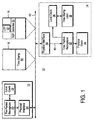
- Figure 1 shows a distributed system 10 which includes a pair of nodes 12 and 14 interconnected via a communication link 40.
- the nodes 12 and 14 include a pair of local clocks 22 and 36, respectively, which keep local time for the respective nodes 12 and 14.
- the nodes 12 and 14 also include a pair of time packet recognizers 20 and 32, respectively, which exchange messages via the communication link 40 to maintain synchronization of the local clocks 22 and 36.
- the time packet recognizer 20 generates a timing data packet 18 and transfers it via the communication link 40 through a physical interface 24 that enables communication via the communication link 40.
- the timing data packet 18 includes a unique timing point (UTP) 52 and a timing data packet (TDP) delimiter 54.
- UTP unique timing point
- TDP timing data packet
- the time-stamp 50 indicates the local time in the node 12 at which the time packet recognizer 20 transferred the timing data packet 18 to the physical interface 24.
- the time packet recognizer 20 generates a follow up packet 16 and transfers it via the communication link 40.
- the follow up packet 16 includes the time-stamp 50.
- the time packet recognizer 32 receives the timing data packet 18 through a physical interface 30 that enables communication via the communication link 40.
- the physical interface 30 generates a set of recovered signals 60 in response to the reception of the timing data packet 18.
- the recovered signals 60 include a recovered bit stream which carries the elements of the timing data packet 18 including the UTP 52 and the TDP delimiter 54.
- the recovered signals 60 include a recovered clock signal for the recovered bit stream.
- the time packet recognizer 32 uses the recovered signals 60 to detect the UTP 52. Upon detection of the UTP 52 in the recovered bit stream, the time packet recognizer 32 causes a time-stamp latch 38 to latch a local time value from the local clock 36. Thereafter, the time packet recognizer 32 verifies whether the timing data packet 18 contains the TDP delimiter 54.
- the TDP delimiter 54 is a unique pattern that distinguishes timing data packets from other types of packets carried on the communication link 40. If the TDP delimiter 54 is not found in the packet 18 then the packet 18 is not a timing data packet and the time packet recognizer 32 discards the time value just latched by the time-stamp latch 38.
- the UTP 52 precedes the TDP delimiter 54 in the timing data packet 18. In yet another embodiment, the UTP 52 and the TDP delimiter 54 are merged into the same indicator in the timing data packet 18.
- the time value held in the time-stamp latch 38 indicates the local time at which the time packet recognizer 32 received the timing data packet 18. Thereafter, the time packet recognizer 32 receives the follow up packet 16 and extracts the time-stamp 50. The difference between the time-stamp 50 and the time value in the time-stamp latch 38 indicates the relative synchronization of the local clocks 22 and 36. Once this difference is computed the time packet recognizer 32 uses it to adjust the time value in the local clock 36 to conform the local clock 36 to the local clock 22.
- the adjustment of the time value in the local clock 36 may be accomplished by implementing the local clock 36 as a counter driven by an oscillator with sufficient stability.
- the least significant few bits of the counter may be implemented as an adder so that the increment on oscillator periods may be occasionally increased or decreased to effectively speed up or slow down the local clock 36 in accordance with the results of the computation of the difference between the time-stamp 50 and the time value held in the time-stamp latch 38.
- the nodes 12 and 14 may be any type of node in the distributed system 10.
- any one or both of the nodes 12 and 14 may be a sensor node or an actuator node or an application controller node or a combination of these in a distributed control system.
- Any one or more of the nodes 12 and 14 may be a computer system such as a personal computer.
- the communication link 40 may be implemented with one or more of a variety of communication mechanisms.
- the communication link 40 is an Ethernet communication network.
- the communication link 40 is a LonTalk field-level control bus which is specialized for the process control environment.
- the communication link 40 may be implemented with time division multiple access (TDMA) or token ring protocols to name only a few possibilities.
- TDMA time division multiple access
- the UTP 52 is a start-of-frame (SOF) delimiter which marks the end of a preamble portion of the packet 18.
- SOF delimiter is a predefined bit pattern which depends on the particular communication protocol being used on the communication link 40.
- the TDP delimiter 54 is a unique multi-cast address which is allocated for timing data packets.
- timing data packets are delimited by mechanisms such as differing carrier frequencies, coding methods, or transmission paths from the carrier frequencies, coding methods, or transmission paths used by other packets.
- the physical interface 30 includes a phase lock loop circuit and may also include a squelch circuit each of which may introduce jitter in the recovered signals 60 received by the time packet recognizer 32. This jitter may cause inaccuracies in the detected time of the UTP 52 by the time packet recognizer 32 which can reduce the overall accuracy of synchronization between the local clocks 22 and 36 which may be obtained by the above technique.
- One method for reducing the negative effects of jitter introduced by the physical interface 30 is to average the differences computed between the time value in the time-stamp latch 38 and the time-stamp 50 for a number of timing data packet and corresponding follow up packet pairs. This computed average may then be used to adjust the local clock 36.
- the time packet recognizer 20 may generate a timing data packet once per second along with a corresponding follow up packet.
- the time packet recognizer 32 latches a time value from the local clock 36 upon detection of each UTP of the received timing data packets and then computes a difference between the latched time value and the time-stamp contained in the corresponding follow up packet. These differences are then averaged for, for example, 10 timing data packets, and the averaged result is then used to adjust the local clock 36.
- the averaging may be performed by the time packet recognizer 32 or by processor associated with the protocol stack 34.
- This averaging technique may also be used if repeaters or gateways or similar communication devices are interposed between the nodes 12 and 14. The averaging would reduce the effects of jitter associated with these types of intervening communication devices.
- FIG. 2 shows an embodiment of the physical interface 30 which includes a UTP detection circuit 74 that improves accuracy in the synchronization of the local clocks 22 and 36 by reducing jitter in the detection of the UTP 52.
- the receiving side of the physical interface 30 includes a coupling circuit 70 such as a transformer, a signal conditioning circuit 72, a phase lock loop (PLL) circuit 76, and a decode circuit 78.
- PLL phase lock loop
- the PLL circuit 76 receives a raw incoming bit stream 64 from the signal conditioning circuit 72 and generates the recovered clock signal of the recovered signals 60.
- the decode circuit 78 uses the recovered clock signal to obtain the recovered bit stream of the recovered signals 60.
- the recovered bit stream is in phase with a local oscillator of the physical interface 30 and this local oscillator usually drifts with respect to the phase of the local oscillator in the physical interface 24. This phase variation may produce jitter in the detection point of the UTP 52 if the recovered signals 60 are used to detect the UTP 52.
- the UTP detection circuit 74 detects the UTP 52 from the raw incoming bit stream 64, thereby eliminating the jitter associated with the recovered signals 60.
- the UTP detection circuit 74 provides a UTP detection signal 62 to the time packet recognizer 32 which causes it to latch a time value from the local clock 36 when the UTP 52 is detected.
- FIG. 3 shows an alternative embodiment of the physical interface 30 which includes a phase error measurement circuit 80 that improves accuracy in the synchronization of the local clocks 22 and 36 by reducing jitter in the detection of the UTP 52.
- the phase error measurement circuit 80 measures the difference in phase between the raw incoming bit stream 64 and the recovered signals 60.
- the phase error measurement circuit 80 provides the time packet recognizer 32 with a phase error signal 66 that indicates the difference in phase.
- the time packet recognizer 32 then uses the phase error signal 66 to correct the time at which it detects the UTP 52.
- the phase error measurement circuit 80 may be implemented with a circuit that triggers a pulse by detecting threshold levels of the raw incoming bit stream 64. The phase of this triggered pulse is then compared to the phase of the recovered signals 60.
- the phase error measurement circuit 80 may include a mixer that measures the phase error.
- Figure 4 shows a distributed system 100 in which the nodes 12 and 14 are coupled to different communication links, the communication link 40 and a communication link 102, respectively.
- a communication device 104 provides communication between nodes connected to the communication link 40 and nodes connected to the communication link 102.
- the communication device 104 receives timing data packets and follow up packets and other packets from the node 12 via the communication link 40 and transfers them to the node 14 via the communication link 102.
- the communication device 104 may be a repeater or a switching hub or a gateway or other similar type of device.
- the communication device 104 introduces a delay in the transfer of each packet from the communication link 40 to the communication link 102 including the timing data packets.
- the amount of delay varies depending upon the implementation of the communication device 104 and network load factors. For example, if the communication device 104 is a repeater it may contain phase lock loop or squelch circuitry that introduces delay. If the communication device 104 is a gateway it may contain buffers whose delay depends on the amount of traffic being routed through the gateway at a particular time. Variations in this delay reduces the accuracy of time synchronization between the local clocks 20 and 36 by introducing jitter into the times at which the UTPs of timing data packets are received by the time packer recognizer 32.
- One method for reducing the effects of the jitter associated with the communication device 104 is for the time packet recognizer 32 to ignore the received timing data packets that have delay greater than a minimum determined delay.
- the time packet recognizer 32 may receive multiple pairs of timing data packets and corresponding follow up packets and compute corresponding differences between the detected UTP time of each timing data packet and the time-stamp of the corresponding follow up packet.
- the minimum difference should be the delay associated with the communication device 104 when its buffers are empty.
- the jitter and delay introduced by the communication device 104 when its buffers are empty is likely to be much less than when its buffers are active.
- the time packet recognizer 32 ignores any timing data packets that have a substantially greater delay than this minimum delay by discarding the corresponding latched local time values and not making any local clock adjustments in response to the timing data packets that are ignored. This prevents adjustments to the local clock 36 which are based on excessive jitter in the communication device 104.
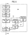
- FIG. 5 shows an embodiment of the communication device 104 which includes mechanisms for reducing time synchronization inaccuracies caused by jitter.
- the communication link 40 to communication link 102 path of the communication device 104 in this embodiment includes a coupling circuit 130, a squelch circuit 132, a signal conditioning circuit 134, a phase lock loop (PLL) circuit 136, a retransmit clock 138, and a preamble regeneration circuit 142.
- PLL phase lock loop
- Packets such as the timing data packet 18 and the follow up packet 16 are received via the communication link 40 by the coupling circuit 130.
- the PLL circuit 136 receives a raw incoming bit stream 110 which carries a received packet.
- the PLL circuit 136 generates a recovered clock signal 112 in response to the raw incoming bit stream 110.
- the retransmit clock circuit 138 uses the recovered clock signal 112 to derive a retransmit clock signal 114.
- the retransmit clock signal 114 includes jitter caused by the PLL circuit 138 and this jitter would reduce the accuracy of the UTP detection in the node 14 if the retransmit clock signal 114 were used to drive the preamble regeneration circuit 142. Instead, this jitter is reduced by a phase error measurement circuit 144 and a delay circuit 140.
- the phase error measurement circuit 144 measures the phase difference between the raw incoming bit stream 110 and the retransmit clock signal 114 and generates a phase error signal 116 that indicates this difference.
- the delay circuit 140 delays the retransmit clock signal 114 to align its phase to the phase of the raw incoming bit stream 110.
- a delayed and phase aligned clock signal 118 is then provided to the preamble regeneration circuit 142.
- the preamble regeneration circuit 142 regenerates preambles for packets relayed from the communication link 40 to the communication link 102.
- the preamble regeneration circuit 142 also relays the bit stream for received packets onto the communication link 102.
- the preamble and relayed packet bit stream are aligned to the phase of the clock signal 118.
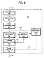
- Figure 6 shows an alternative embodiment of the communication device 104 which includes mechanisms for reducing time synchronization inaccuracies caused by jitter.
- the output of the preamble regeneration circuit 142 is clocked by the retransmit clock 114 and is delayed by an output delay circuit 152.
- the amount of delay introduced by the output delay circuit 152 is controlled by the phase error signal 116 so that the output from the output delay circuit 152 is aligned in phase with the raw incoming bit stream 110.
- the output delay circuit 152 may be implemented, for example, with a tapped delay line wherein the bit stream from the preamble generation circuit 142 is steered through the appropriate tapped delay line by the phase error signal 116.
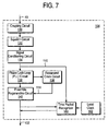
- FIG. 7 shows an embodiment of the communication device 104 which includes mechanisms for measuring the delay introduced in the communication device 104 and for passing the measured delay onto the node 14 in a follow up packet.
- the communication device 104 includes a time packet recognizer 160 that detects the UTP 52 in the raw incoming bit stream 110 and that detects the UTP 52 in the output bit stream on the communication link 102.
- the time packet recognizer 160 obtains a time value from a local clock 162 when it detects the UTP 52 in the raw incoming bit stream 110 and obtains a time value from the local clock 162 when it detects the UTP 52 on the communication link 102.
- the difference in these time values is the delay associated with the communication device 104.
- the time packet recognizer 160 generates a follow up packet that contains the delay associated with the communication device 104 and transfers it via the communication link 102.
- the time packet recognizer 32 obtains this follow up packet and uses the delay associated with the communication device 104 to correct the difference between the time-stamp 50 and the time value in the time-stamp latch 38 when adjusting the local clock 36.
Landscapes
- Engineering & Computer Science (AREA)
- Theoretical Computer Science (AREA)
- Physics & Mathematics (AREA)
- General Engineering & Computer Science (AREA)
- General Physics & Mathematics (AREA)
- Computer Networks & Wireless Communication (AREA)
- Signal Processing (AREA)
- Synchronisation In Digital Transmission Systems (AREA)
- Data Exchanges In Wide-Area Networks (AREA)
Abstract
Description
Claims (10)
- A distributed system, comprising:first node (12) having a local clock (22) and circuitry that generates a timing data packet (18) and a follow up packet (16), the timing data packet (18) having a unique timing point (52) and a delimiter (54) and the follow up packet (16) having a time-stamp (50) obtained from the local clock (22) that indicates a time at which the timing data packet (18) is generated;second node (14) having circuitry that receives the timing data packet (18) and the follow up packet (16) via the communication link, the second node (14) having a local clock (36) and circuitry that obtains a local time value from the local clock (36) when the unique timing point (52) is detected and that discards the local time value if the delimiter (54) is not detected, such that a difference between the time-stamp (50) of the follow up packet (16) and the local time value if not discarded indicates a relative synchronization of the local clocks (22 and 36).
- The distributed system of claim 1, wherein the circuitry that receives the timing data packet (18) comprises:signal conditioning circuit that generates a raw bit stream in response to the timing data packet (18);phase lock loop circuit that recovers a clock signal from the raw bit stream;circuitry generates a detection signal by detecting the unique timing point (52) in the raw bit stream such that the detection signal reduces jitter in the detection of the unique timing point (52) that is associated with the phase lock loop circuit.
- The distributed system of claim 1, wherein the circuitry that receives the timing data packet (18) comprises:signal conditioning circuit that generates a raw bit stream in response to the timing data packet (18);circuitry that generates a set of recovered signals from the raw bit stream;circuitry generates a phase error signal that indicates a phase difference between the raw bit stream and the recovered signals such that the phase error signal enables a correction for jitter associated with the recovered signals.
- The distributed system of claim 1, wherein the second node (14) receives a series of timing data packets and corresponding follow up packets via the communication link and further comprises means for determining an average of a set of differences between a series of time values obtained from the local clock (36) in response to the series of timing data packets and a corresponding series of time-stamps contained in the corresponding follow up packets such that the average indicates a relative synchronization of the local clocks (22 and 36) of the first and second nodes (12 and 14).
- A distributed system, comprising:first node (12) coupled to a first communication link (40) and having circuitry that generates a timing data packet (18) that includes a unique timing point (52) and circuitry that transfers the timing data packet (18) via the first communication link (40);second node (14) having circuitry for receiving the timing data packet (18) via a second communication link (102) and circuitry for detecting the unique timing point (52) and for determining a delay between a time at which the first node (12) generated the timing data packet (18) and a time at which the unique timing point (52) is detected at the second node (14);communication circuit that transfers the timing data packet (18) between the first communication link (40) and the second communication link (102), the communication circuit having means for reducing an inaccuracy in the delay between the time at which the first node (12) generated the timing data packet (18) and the time at which the unique timing point (52) is detected at the second node (14) wherein the inaccuracy is caused by jitter introduced by the communication circuit.
- The distributed system of claim 5, wherein the means for reducing an inaccuracy in the delay comprises:signal conditioning circuit that generates a raw bit stream in response to the timing data packet (18);phase lock loop circuit that generates a recovered clock signal from the raw bit stream;circuitry that determines a phase error between the recovered clock signal and the raw bit stream and that generates a delayed clock signal in response to the phase error and the recovered clock signal such that delayed clock signal is aligned to the raw bit stream;circuitry that regenerates a preamble for transferring the timing data packet (18) over the second communication link (102) such that the preamble is aligned to the delayed clock signal.
- The distributed system of claim 5, wherein the means for reducing an inaccuracy in the delay comprises:signal conditioning circuit that generates a raw bit stream in response to the timing data packet (18);phase lock loop circuit that generates a recovered clock signal from the raw bit stream;circuitry that determines a phase error between the recovered clock signal and the raw bit stream;circuitry that regenerates a preamble for transferring the timing data packet (18) over the second communication link (102);circuitry that delays the preamble in response to the phase error such that the preamble transferred over the second communication link (102) is aligned to the raw bit stream.
- The distributed system of claim 5, wherein the means for reducing an inaccuracy in the delay includes circuitry that measures a delay introduced by the communication circuit and that transfers a follow up packet (16) containing the delay introduced by the communication circuit to the second node (14) via the second communication link (102) such that the second node (14) uses the delay introduced by the communication circuit to correct the delay between the time at which the first node (12) generated the timing data packet (18) and the time at which the unique timing point (52) is detected at the second node (14).
- A distributed system, comprising;first node (12) coupled to a first communication link (40) and having circuitry that generates a timing data packet (18) that includes a unique timing point (52) and circuitry that transfers the timing data packet (18) via the first communication link (40);communication circuit that transfers the timing data packet (18) between the first communication link (40) and a second communication link (102);second node (14) having circuitry for receiving the timing data packet (18) via the second communication link (102) and circuitry for detecting the unique timing point (52) and for determining a delay between a time at which the first node (12) generated the timing data packet (18) and a time at which the unique timing point (52) is detected at the second node (14), the second node (14) having circuitry for ignoring the timing data packet (18) if the delay between the time at which the first node (12) generated the timing data packet (18) and the time at which the unique timing point (52) is detected at the second node (14) exceeds a minimum delay.
- The distributed system of claim 9, wherein the second node (14) further comprises means for determining the minimum delay by measuring a series of delays between a series of times at which the first node (12) generated a series of timing data packets and a series of times at which a series of corresponding unique timing point (52)s are detected at the second node (14) and then selecting a minimum of the series of delays.
Priority Applications (2)
| Application Number | Priority Date | Filing Date | Title |
|---|---|---|---|
| EP05010662A EP1564919B1 (en) | 1998-09-10 | 1999-06-10 | Enhancements to time synchronization in distributed systems |
| EP05018718A EP1598968B1 (en) | 1998-09-10 | 1999-06-10 | Enhancements to time synchronization in distributed systems |
Applications Claiming Priority (2)
| Application Number | Priority Date | Filing Date | Title |
|---|---|---|---|
| US151017 | 1998-09-10 | ||
| US09/151,017 US6278710B1 (en) | 1998-09-10 | 1998-09-10 | Enhancements to time synchronization in distributed systems |
Related Child Applications (2)
| Application Number | Title | Priority Date | Filing Date |
|---|---|---|---|
| EP05018718A Division EP1598968B1 (en) | 1998-09-10 | 1999-06-10 | Enhancements to time synchronization in distributed systems |
| EP05010662A Division EP1564919B1 (en) | 1998-09-10 | 1999-06-10 | Enhancements to time synchronization in distributed systems |
Publications (3)
| Publication Number | Publication Date |
|---|---|
| EP0986202A2 true EP0986202A2 (en) | 2000-03-15 |
| EP0986202A3 EP0986202A3 (en) | 2005-02-09 |
| EP0986202B1 EP0986202B1 (en) | 2006-04-12 |
Family
ID=22536990
Family Applications (2)
| Application Number | Title | Priority Date | Filing Date |
|---|---|---|---|
| EP05010662A Expired - Lifetime EP1564919B1 (en) | 1998-09-10 | 1999-06-10 | Enhancements to time synchronization in distributed systems |
| EP99111339A Expired - Lifetime EP0986202B1 (en) | 1998-09-10 | 1999-06-10 | Enhancements to time synchronization in distributed systems |
Family Applications Before (1)
| Application Number | Title | Priority Date | Filing Date |
|---|---|---|---|
| EP05010662A Expired - Lifetime EP1564919B1 (en) | 1998-09-10 | 1999-06-10 | Enhancements to time synchronization in distributed systems |
Country Status (4)
| Country | Link |
|---|---|
| US (1) | US6278710B1 (en) |
| EP (2) | EP1564919B1 (en) |
| JP (1) | JP2000099485A (en) |
| DE (2) | DE69933594T2 (en) |
Cited By (13)
| Publication number | Priority date | Publication date | Assignee | Title |
|---|---|---|---|---|
| WO2003092196A1 (en) * | 2002-04-24 | 2003-11-06 | Grundig Multimedia B.V. | Method and device for synchronizing a receiver with a transmitter during a transmission of data over an asynchronous network |
| WO2004075446A1 (en) * | 2003-02-20 | 2004-09-02 | Zarlink Semiconductor Inc. | Alignment of clocks over multiple packet networks |
| FR2858075A1 (en) * | 2003-07-25 | 2005-01-28 | Bosch Gmbh Robert | Slave and master units time generators synchronizing method for motor vehicle, involves correcting current time values and recording time value by slave units, and inserting value in synchronization message by master unit |
| EP1324520A3 (en) * | 2001-12-24 | 2005-02-09 | Agilent Technologies, Inc. | Synchronization in a distributed system |
| EP1645935A2 (en) | 2004-10-07 | 2006-04-12 | Westerngeco Seismic Holdings Limited | Synchronization of real time clocks of nodes in a network environment |
| EP1672384A3 (en) * | 2003-07-03 | 2007-10-24 | NavCom Technology, Inc. | Two-way RF ranging system and method for local positioning |
| WO2008110414A1 (en) * | 2007-03-09 | 2008-09-18 | Robert Bosch Gmbh | Method, can bus driver, and can bus system for recovering a clock frequency of a can bus |
| WO2009146472A1 (en) * | 2008-06-02 | 2009-12-10 | Fts Computertechnik Gmbh | Method for synchronizing local clocks in a distributed computer network |
| US8665884B2 (en) | 2011-08-25 | 2014-03-04 | Honeywell International Inc. | Embedded end-to-end delay information for data networks |
| US9306766B2 (en) | 2011-03-28 | 2016-04-05 | Honeywell International Inc. | Versatile source port enforcement for data networks |
| EP1607828A3 (en) * | 2004-06-15 | 2016-05-11 | NTT DoCoMo, Inc. | Method for managing data acquisition time |
| EP2034643A3 (en) * | 2007-09-04 | 2017-03-29 | Electronics and Telecommunications Research Institute | Apparatus and method for synchronizing time information using key re-synchronization frame in encryption communications |
| WO2024136956A1 (en) * | 2022-12-19 | 2024-06-27 | Microsoft Technology Licensing, Llc | Processor synchronization systems and methods |
Families Citing this family (46)
| Publication number | Priority date | Publication date | Assignee | Title |
|---|---|---|---|---|
| GB9821518D0 (en) * | 1998-10-02 | 1998-11-25 | Sony Uk Ltd | Digital signal processing and signal format |
| CN1166249C (en) * | 1999-01-19 | 2004-09-08 | 西门子公司 | Method for the time synchronisation of a computer network and computer network with time synchronisation |
| US6661811B1 (en) * | 1999-02-12 | 2003-12-09 | Koninklijke Philips Electronics N.V. | Method of and apparatus for communicating isochronous data |
| DE19912556A1 (en) * | 1999-03-19 | 2000-09-21 | Philips Corp Intellectual Pty | Wireless network with user clock synchronization |
| US6512990B1 (en) * | 2000-01-05 | 2003-01-28 | Agilent Technologies, Inc. | Distributed trigger node |
| US6944187B1 (en) * | 2000-08-09 | 2005-09-13 | Alcatel Canada Inc. | Feature implementation in a real time stamp distribution system |
| US6853708B1 (en) | 2000-12-29 | 2005-02-08 | Bellsouth Intellectual Property Corporation | End-to-end network testing |
| US7151819B2 (en) * | 2000-12-29 | 2006-12-19 | Bellsouth Ip Corporation | End-to-end network testing |
| DE50200454D1 (en) * | 2001-06-07 | 2004-06-24 | Siemens Ag | Method for transmitting time information over a data packet network |
| GB2385684A (en) * | 2002-02-22 | 2003-08-27 | Sony Uk Ltd | Frequency synchronisation of clocks |
| US7114091B2 (en) * | 2002-03-18 | 2006-09-26 | National Instruments Corporation | Synchronization of distributed systems |
| US20040008973A1 (en) * | 2002-07-12 | 2004-01-15 | Marshall Robert Alexander | Method and system for synchronizing operation of remote timer with centeral control control unit |
| AU2003297686A1 (en) * | 2002-12-06 | 2004-06-30 | Thomson Licensing S.A. | A method and system for remote tuning and clock synchronization |
| US7379480B2 (en) * | 2003-01-16 | 2008-05-27 | Rockwell Automation Technologies, Inc. | Fast frequency adjustment method for synchronizing network clocks |
| US7233316B2 (en) * | 2003-05-01 | 2007-06-19 | Thomson Licensing | Multimedia user interface |
| US8432942B1 (en) | 2003-05-16 | 2013-04-30 | Apple Inc. | Providing a timing source for multiple nodes coupled to a circuit-switched network |
| WO2005077063A2 (en) * | 2004-02-09 | 2005-08-25 | Semtech Corporation | Method and apparatus for aligning time references when separated by an unreliable data packet network |
| US7315791B2 (en) * | 2004-02-18 | 2008-01-01 | National Instruments Corporation | Application programming interface for synchronizing multiple instrumentation devices |
| US8930579B2 (en) * | 2004-09-13 | 2015-01-06 | Keysight Technologies, Inc. | System and method for synchronizing operations of a plurality of devices via messages over a communication network |
| US7561598B2 (en) * | 2004-09-13 | 2009-07-14 | Agilent Technologies, Inc. | Add-on module for synchronizing operations of a plurality of devices |
| US20060059269A1 (en) * | 2004-09-13 | 2006-03-16 | Chien Chen | Transparent recovery of switch device |
| US20060056424A1 (en) * | 2004-09-15 | 2006-03-16 | Yolin Lih | Packet transmission using output buffer |
| US7333468B1 (en) * | 2005-05-16 | 2008-02-19 | Sun Microsystems, Inc. | Digital phase locked loops for packet stream rate matching and restamping |
| US7990887B2 (en) * | 2006-02-22 | 2011-08-02 | Cisco Technology, Inc. | Sampling test of network performance |
| US20080031283A1 (en) * | 2006-08-07 | 2008-02-07 | Martin Curran-Gray | Time synchronization for network aware devices |
| EP2034642B1 (en) * | 2007-09-07 | 2011-10-26 | Siemens Aktiengesellschaft | Method for transmitting synchronisation messages in a communications network |
| US8559412B1 (en) | 2007-12-31 | 2013-10-15 | Rockstar Consortium Us Lp | Communication time information in a network to enable synchronization |
| CN101926154B (en) * | 2008-02-05 | 2013-07-10 | 富士通株式会社 | Method for measuring frame loss, system for measuring frame loss, and device for measuring frame loss |
| US8073976B2 (en) | 2008-03-27 | 2011-12-06 | Microsoft Corporation | Synchronizing clocks in an asynchronous distributed system |
| CN101753609B (en) * | 2008-12-15 | 2012-09-19 | 中国移动通信集团公司 | Version control method, nodes and system of distributed system |
| EP2401827A1 (en) * | 2009-02-24 | 2012-01-04 | Telefonaktiebolaget L M Ericsson (PUBL) | Clock recovery in a communications network |
| EP2228927A1 (en) * | 2009-03-12 | 2010-09-15 | Alcatel Lucent | Method for processing distributed data having a chosen type for synchronizing communication nodes of a data packet network, and associated device |
| WO2010132941A1 (en) | 2009-05-20 | 2010-11-25 | Chronologic Pty. Ltd. | Universal time-based extensions for instrumentation |
| US8307235B2 (en) | 2010-05-05 | 2012-11-06 | National Instruments Corporation | Cross controller clock synchronization |
| US20120278421A1 (en) * | 2011-04-27 | 2012-11-01 | Centec Networks (Suzhou) Co., Ltd. | Providing a data sample in a measurement and control system |
| US9756153B2 (en) | 2011-06-01 | 2017-09-05 | Finite State Research Llc | Method for improving accuracy in computation of one-way transfer time for network time synchronization |
| US9628209B2 (en) | 2013-01-17 | 2017-04-18 | Viavi Solutions Inc. | Time synchronization in distributed network testing equipment |
| US9759703B2 (en) | 2013-09-27 | 2017-09-12 | Li-Cor, Inc. | Systems and methods for measuring gas flux |
| US9723610B2 (en) * | 2015-04-07 | 2017-08-01 | Qualcomm Incorporated | Multi-layer timing synchronization framework |
| DE102016200964A1 (en) * | 2016-01-25 | 2017-07-27 | Siemens Aktiengesellschaft | Method for transmitting information in a communications network |
| CN110520815B (en) * | 2016-10-17 | 2023-11-28 | 思科技术公司 | Method and system for adding precise timestamps |
| US10848160B2 (en) | 2018-07-10 | 2020-11-24 | Aerotech, Inc. | Devices, systems, and methods for reducing jitter in control systems |
| WO2020201950A1 (en) | 2019-04-01 | 2020-10-08 | Zomojo Pty Ltd | A method and apparatus for network time syncing |
| AU2020280261A1 (en) | 2019-05-22 | 2021-10-07 | Zomojo Pty Ltd | A networking apparatus and a method for networking |
| US11804921B2 (en) | 2019-06-25 | 2023-10-31 | Cisco Technology, Inc. | Method and apparatus for high precision time stamping |
| US11438273B2 (en) | 2020-07-20 | 2022-09-06 | Altiostar Networks, Inc. | Real-time processing in wireless communications systems |
Family Cites Families (8)
| Publication number | Priority date | Publication date | Assignee | Title |
|---|---|---|---|---|
| US4890222A (en) * | 1984-12-17 | 1989-12-26 | Honeywell Inc. | Apparatus for substantially syncronizing the timing subsystems of the physical modules of a local area network |
| DE3638947C2 (en) * | 1986-11-14 | 1995-08-31 | Bosch Gmbh Robert | Process for the synchronization of computers of a multi-computer system and multi-computer system |
| SE466123B (en) * | 1989-04-25 | 1991-12-16 | Kvaser Consultant Ab | DEVICE FOR SYNCONIZING DATA IN A COMPUTER SYSTEM INCLUDING A COMMON SERIAL DATA COMMUNICATION CHANNEL |
| US5537549A (en) * | 1993-04-28 | 1996-07-16 | Allen-Bradley Company, Inc. | Communication network with time coordinated station activity by time slot and periodic interval number |
| US5566180A (en) * | 1994-12-21 | 1996-10-15 | Hewlett-Packard Company | Method for recognizing events and synchronizing clocks |
| US5822383A (en) * | 1995-12-15 | 1998-10-13 | Cisco Technology, Inc. | System and method for maintaining network synchronization utilizing digital phase comparison techniques with synchronous residual time stamps |
| US5640388A (en) * | 1995-12-21 | 1997-06-17 | Scientific-Atlanta, Inc. | Method and apparatus for removing jitter and correcting timestamps in a packet stream |
| US6665316B1 (en) * | 1998-09-29 | 2003-12-16 | Agilent Technologies, Inc. | Organization of time synchronization in a distributed system |
-
1998
- 1998-09-10 US US09/151,017 patent/US6278710B1/en not_active Expired - Lifetime
-
1999
- 1999-06-10 DE DE69933594T patent/DE69933594T2/en not_active Expired - Fee Related
- 1999-06-10 EP EP05010662A patent/EP1564919B1/en not_active Expired - Lifetime
- 1999-06-10 DE DE69930806T patent/DE69930806T2/en not_active Expired - Fee Related
- 1999-06-10 EP EP99111339A patent/EP0986202B1/en not_active Expired - Lifetime
- 1999-08-26 JP JP11239133A patent/JP2000099485A/en active Pending
Cited By (20)
| Publication number | Priority date | Publication date | Assignee | Title |
|---|---|---|---|---|
| EP1324520A3 (en) * | 2001-12-24 | 2005-02-09 | Agilent Technologies, Inc. | Synchronization in a distributed system |
| US7251199B2 (en) | 2001-12-24 | 2007-07-31 | Agilent Technologies, Inc. | Distributed system time synchronization including a timing signal path |
| WO2003092196A1 (en) * | 2002-04-24 | 2003-11-06 | Grundig Multimedia B.V. | Method and device for synchronizing a receiver with a transmitter during a transmission of data over an asynchronous network |
| WO2004075446A1 (en) * | 2003-02-20 | 2004-09-02 | Zarlink Semiconductor Inc. | Alignment of clocks over multiple packet networks |
| KR100740731B1 (en) * | 2003-02-20 | 2007-07-19 | 자링크 세미컨덕터, 인크 | Alignment of clocks over multiple packet networks |
| US7376156B2 (en) | 2003-02-20 | 2008-05-20 | Zarlink Semiconductor Inc. | Alignment of clocks over multiple packet networks |
| EP1672384A3 (en) * | 2003-07-03 | 2007-10-24 | NavCom Technology, Inc. | Two-way RF ranging system and method for local positioning |
| FR2858075A1 (en) * | 2003-07-25 | 2005-01-28 | Bosch Gmbh Robert | Slave and master units time generators synchronizing method for motor vehicle, involves correcting current time values and recording time value by slave units, and inserting value in synchronization message by master unit |
| EP1607828A3 (en) * | 2004-06-15 | 2016-05-11 | NTT DoCoMo, Inc. | Method for managing data acquisition time |
| US7768931B2 (en) | 2004-10-07 | 2010-08-03 | Westerngeco L.L.C. | Hardware-based network packet timestamps: improved network clock synchronization |
| EP1645935A2 (en) | 2004-10-07 | 2006-04-12 | Westerngeco Seismic Holdings Limited | Synchronization of real time clocks of nodes in a network environment |
| EP1645935A3 (en) * | 2004-10-07 | 2008-04-09 | Westerngeco Seismic Holdings Limited | Synchronization of real time clocks of nodes in a network environment |
| WO2008110414A1 (en) * | 2007-03-09 | 2008-09-18 | Robert Bosch Gmbh | Method, can bus driver, and can bus system for recovering a clock frequency of a can bus |
| US8356201B2 (en) | 2007-03-09 | 2013-01-15 | Robert Bosch Gmbh | Method, CAN bus driver and CAN bus system for the recovery of a clock frequency of a CAN bus |
| EP2034643A3 (en) * | 2007-09-04 | 2017-03-29 | Electronics and Telecommunications Research Institute | Apparatus and method for synchronizing time information using key re-synchronization frame in encryption communications |
| WO2009146472A1 (en) * | 2008-06-02 | 2009-12-10 | Fts Computertechnik Gmbh | Method for synchronizing local clocks in a distributed computer network |
| US9306766B2 (en) | 2011-03-28 | 2016-04-05 | Honeywell International Inc. | Versatile source port enforcement for data networks |
| US8665884B2 (en) | 2011-08-25 | 2014-03-04 | Honeywell International Inc. | Embedded end-to-end delay information for data networks |
| WO2024136956A1 (en) * | 2022-12-19 | 2024-06-27 | Microsoft Technology Licensing, Llc | Processor synchronization systems and methods |
| US12372998B2 (en) | 2022-12-19 | 2025-07-29 | Microsoft Technology Licensing, Llc | Synchronization of integrated circuit dies that contain a processor and clock generator by adjusting delay lines based on phase count |
Also Published As
| Publication number | Publication date |
|---|---|
| EP0986202B1 (en) | 2006-04-12 |
| DE69933594D1 (en) | 2006-11-23 |
| EP0986202A3 (en) | 2005-02-09 |
| EP1564919A1 (en) | 2005-08-17 |
| EP1564919B1 (en) | 2006-10-11 |
| DE69930806T2 (en) | 2006-08-31 |
| DE69933594T2 (en) | 2007-02-01 |
| DE69930806D1 (en) | 2006-05-24 |
| US6278710B1 (en) | 2001-08-21 |
| JP2000099485A (en) | 2000-04-07 |
Similar Documents
| Publication | Publication Date | Title |
|---|---|---|
| US6278710B1 (en) | Enhancements to time synchronization in distributed systems | |
| JP4227708B2 (en) | Distributed system | |
| EP0722233B1 (en) | Timing in a data communications network | |
| CN1934809B (en) | Method and apparatus for calibrating a time reference when separated by an unreliable data packet network | |
| CN102577194B (en) | System and method for synchronizing clocks within a distributed network | |
| EP1198085B1 (en) | Cycle synchronization between interconnected sub-networks | |
| EP0413286B1 (en) | Data synchronous transfer system using a fiber distributed data exchange interface | |
| JP2000099485A5 (en) | ||
| EP2709298A1 (en) | Synchronization method and electronic apparatus using redundant links | |
| Hartwich et al. | Introducing can xl into can networks | |
| US20140307562A1 (en) | Packet loss counter | |
| US20040202203A1 (en) | Method and apparatus for maintaining synchronization in a communication system | |
| EP1598968B1 (en) | Enhancements to time synchronization in distributed systems | |
| KR20010039212A (en) | Apparatus for setting time stamp offset and method thereof | |
| US7711010B2 (en) | Phase-locked loop for maintaining system synchronization through packet dropout | |
| Komes et al. | IEEE 1588 for redundant ethernet networks | |
| US11870554B1 (en) | Enhanced ethernet timestamping on RGMII using existing DLL | |
| US20030126489A1 (en) | Method, apparatus, and system for high speed data transfer between electronic devices | |
| EP0161825B1 (en) | A control mechanism for a ring communication system | |
| EP1467507B1 (en) | Method and apparatus for maintaining synchronization in a communication system | |
| US20250343612A1 (en) | Precisely capturing time of an event in processing circuitry of an optical module | |
| WO2025036628A1 (en) | Synchronization between a first and a second time domain | |
| FI108976B (en) | Procedure for synchronizing local real-time counters | |
| Novák | Sample Point Position Measurement of Controller Area Network Nodes | |
| JPH0435934B2 (en) |
Legal Events
| Date | Code | Title | Description |
|---|---|---|---|
| PUAI | Public reference made under article 153(3) epc to a published international application that has entered the european phase |
Free format text: ORIGINAL CODE: 0009012 |
|
| AK | Designated contracting states |
Kind code of ref document: A2 Designated state(s): AT BE CH CY DE DK ES FI FR GB GR IE IT LI LU MC NL PT SE |
|
| AX | Request for extension of the european patent |
Free format text: AL;LT;LV;MK;RO;SI |
|
| RAP1 | Party data changed (applicant data changed or rights of an application transferred) |
Owner name: AGILENT TECHNOLOGIES, INC. |
|
| RAP1 | Party data changed (applicant data changed or rights of an application transferred) |
Owner name: AGILENT TECHNOLOGIES INC. |
|
| RAP1 | Party data changed (applicant data changed or rights of an application transferred) |
Owner name: AGILENT TECHNOLOGIES INC. A DELAWARE CORPORATION |
|
| RAP1 | Party data changed (applicant data changed or rights of an application transferred) |
Owner name: AGILENT TECHNOLOGIES, INC. (A DELAWARE CORPORATION |
|
| PUAL | Search report despatched |
Free format text: ORIGINAL CODE: 0009013 |
|
| AK | Designated contracting states |
Kind code of ref document: A3 Designated state(s): AT BE CH CY DE DK ES FI FR GB GR IE IT LI LU MC NL PT SE |
|
| AX | Request for extension of the european patent |
Extension state: AL LT LV MK RO SI |
|
| 17P | Request for examination filed |
Effective date: 20050517 |
|
| 17Q | First examination report despatched |
Effective date: 20050620 |
|
| GRAP | Despatch of communication of intention to grant a patent |
Free format text: ORIGINAL CODE: EPIDOSNIGR1 |
|
| AKX | Designation fees paid |
Designated state(s): DE GB |
|
| GRAS | Grant fee paid |
Free format text: ORIGINAL CODE: EPIDOSNIGR3 |
|
| GRAA | (expected) grant |
Free format text: ORIGINAL CODE: 0009210 |
|
| AK | Designated contracting states |
Kind code of ref document: B1 Designated state(s): DE GB |
|
| REG | Reference to a national code |
Ref country code: GB Ref legal event code: FG4D |
|
| REF | Corresponds to: |
Ref document number: 69930806 Country of ref document: DE Date of ref document: 20060524 Kind code of ref document: P |
|
| RAP2 | Party data changed (patent owner data changed or rights of a patent transferred) |
Owner name: AGILENT TECHNOLOGIES, INC. |
|
| PLBE | No opposition filed within time limit |
Free format text: ORIGINAL CODE: 0009261 |
|
| 26N | No opposition filed |
Effective date: 20070115 |
|
| PGFP | Annual fee paid to national office [announced via postgrant information from national office to epo] |
Ref country code: GB Payment date: 20070628 Year of fee payment: 9 |
|
| GBPC | Gb: european patent ceased through non-payment of renewal fee |
Effective date: 20080610 |
|
| PG25 | Lapsed in a contracting state [announced via postgrant information from national office to epo] |
Ref country code: GB Free format text: LAPSE BECAUSE OF NON-PAYMENT OF DUE FEES Effective date: 20080610 |
|
| PGFP | Annual fee paid to national office [announced via postgrant information from national office to epo] |
Ref country code: DE Payment date: 20090604 Year of fee payment: 11 |
|
| PG25 | Lapsed in a contracting state [announced via postgrant information from national office to epo] |
Ref country code: DE Free format text: LAPSE BECAUSE OF NON-PAYMENT OF DUE FEES Effective date: 20110101 |