EP0986201A2 - A wide band contiguous multiplexer having a contiguous diplexer - Google Patents
A wide band contiguous multiplexer having a contiguous diplexer Download PDFInfo
- Publication number
- EP0986201A2 EP0986201A2 EP99304891A EP99304891A EP0986201A2 EP 0986201 A2 EP0986201 A2 EP 0986201A2 EP 99304891 A EP99304891 A EP 99304891A EP 99304891 A EP99304891 A EP 99304891A EP 0986201 A2 EP0986201 A2 EP 0986201A2
- Authority
- EP
- European Patent Office
- Prior art keywords
- contiguous
- filters
- multiplexer
- diplexer
- coupled
- Prior art date
- Legal status (The legal status is an assumption and is not a legal conclusion. Google has not performed a legal analysis and makes no representation as to the accuracy of the status listed.)
- Withdrawn
Links
Images

Classifications
-
- H—ELECTRICITY
- H01—ELECTRIC ELEMENTS
- H01P—WAVEGUIDES; RESONATORS, LINES, OR OTHER DEVICES OF THE WAVEGUIDE TYPE
- H01P1/00—Auxiliary devices
- H01P1/20—Frequency-selective devices, e.g. filters
- H01P1/213—Frequency-selective devices, e.g. filters combining or separating two or more different frequencies
Definitions
- the present invention relates generally to multiplexers, and more particularly, to extended band, multiple channel satellite multiplexers.
- One conventional multiplexer required the use of wide band frequency gap between some of the channels of the multiplexer to realise a multiplexer/diplexer combination, which is pseudocontiguous. Additional directional filters were required to fill the frequency gap and to create contiguous multiplexer.
- the prior art approach used a high attenuation diplexer and a directional filter to realise contiguous multiplexing. It would be desirable to eliminate the directional filters to provide a contiguous multiplexer.
- a multiplexer comprises a first section including a plurality of contiguous channel filters having a first plurality of inputs and a first waveguide manifold respectively coupled to the channel filters; a second section including a plurality of contiguous channel filters having a second plurality of inputs and a second waveguide manifold respectively coupled to the contiguous channel filters; and, a contiguous diplexer coupled to outputs of the first and second waveguide manifolds.
- the directional filters used in the prior art are not needed to realise the contiguous multiplexer of the present invention.
- the multiplexer utilizes the low attentuation, contiguous diplexer to combine the two sections of the multiplexer.
- the approach of the present invention takes advantage of the constructive interaction between these filters to realise an equivalent contiguous multiplexer. This enables realisation of a wide band contiguous multiplexer, which previously was impossible to tune.
- the diplexer eliminates spurious modes of the filters, spurious wveguide modes, and out of band interaction between the two portions of the multiplexer. Therefore, tuning of the multiplexer is possible.
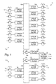
- Figure 1 illustrates an example of a multiplexer 10 comprising first and second sections 11a and 11b.
- the first section 11a has a plurality of inputs 12 that are respectively coupled by way of a plurality of circulators 13 to a plurality of four-pole channel filters 14a.
- the channel filters 14a may have any number of poles dictated by the design and application of the multiplexer 10.
- Each of the plurality of four-pole channel filters 14a are coupled to a first waveguide manifold 15a.
- An output of the first waveguide manifold 15a is coupled by way of a first output circulator 16a to a first low pass filter 17a.
- the second section 11b has a plurality of inputs 12 that are respectively coupled by way of a plurality of circulators 13 to a plurality of four-pole contiguous channel filters 14b.
- the channel filters 14b may have any number of poles dictated by the design and application of the multiplexer 10.
- Each of the plurality of four-pole contiguous channel filters 14b are coupled to a second waveguide manifold 15b.
- An output of the second waveguide manifold 15b is coupled by way of a second output circulator 16b to a second low pass filter 17b.
- Each of the low pass filters 17a, 17b is coupled to an input of a contiguous diplexer 18.
- the contiguous diplexer 18 outputs a multiplexed signal corresponding to the signals input at the inputs 12 of each of the sections 11a and 11b.
- the diplexer 18 is a low attenuation, contiguous diplexer 18 that combines the outputs of the two sections 11a and 11b of the multiplexer 10.
- the channel filters 14a are designed and tuned in tandem with contiguous diplexer filters 18a of the diplexer 18. This approach takes advantage of the constructive interaction between the channel filters 14a and the contiguous diplexer filters 18a to realise an equivalent contiguous multiplexer 10.
- the approach of the present invention enables realisation of a wide band contiguous multiplexer 10, which previously was impossible to tune.
- the contiguous diplexer 18 eliminates spurious modes of the channel filters 14a, spurious modes in the waveguide manifolds 15a and 15b, and out-of-band interaction between the two sections 11a and 11b of the multiplexer 10. Therefore, the practical realisation (tuning) of the mulitplexer 10 is possible.
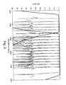
- Figure 2 is a graph that illustrates the response of the diplexer 18 of the multiplexer 10 shown in Figure 1 operating at C-band.
- Figure 2 shows a graph of loss in dB versus frequency in MHz for a C-band implementation of the multiplexer 10.
- Figure 2 illustrates the standard or normal band (dashed line) derived from the first section 11a of the multiplexer 10, and the extended band (to the left of the dashed line) derived from the second section 11b of the multiplexer 10.
- Figures 3 is a graph that illustrates tuning of the multiplexer 10 of Figure 1. More specifically, Figure 3 shows a graph of loss in dB versus frequency in MHz for an exemplary C-band multiplexer 10, such as is shown in Figure 1. Figure 3 shows each of the five extended channels derived from the five contiguous channel filters 14b of the second section 11b and the thirteen standard channels derived from the thirteen contiguous channel filters 14a of the first section 11a.
- the present invention has been described with reference to C-band multiplexer 10, it is to be understood that the present invention is not band-limited.
- the concepts of the present invention may be used to produce a multiplexer 10 that operates in the S, C, X, Ku, K, Ka, Q, V, or W frequency bands, for example, or any other desired frequency band. Consequently, the present invention is not limited to any particular operating frequency band.
Landscapes
- Control Of Motors That Do Not Use Commutators (AREA)
- Radio Relay Systems (AREA)
Abstract
Description
Claims (9)
- A multiplexer comprising:a first section (11a) including a plurality of contiguous channel filters (14a) having a first plurality of inputs (12) and a first waveguide manifold (15a) respectively coupled to the channel filters;a second section (11b) including a plurality of contiguous channel filters (14b) having a second plurality of inputs (12) and a second waveguide manifold (15b) respectively coupled to the contiguous channel filters; and,a contiguous diplexer (18) coupled to outputs of the first and second waveguide manifolds.
- A multiplexer according to claim 1, wherein the first section (11a) comprises a first output circulator (16a) coupled to an output of the first waveguide manifold, and a first low pass filter (17a) coupled to an output of the first output circulator, and wherein the second section (11b) comprises a second output circulator (16b) coupled to an output of the second waveguide manifold, and a second low pass filter (17b) coupled to an output of the second output circulator.
- A multiplexer according to claim 1 or 2, wherein the channel filters (14a) comprise four-pole channel filters (14a).
- A multiplexer according to any preceding claim, wherein the channel filters (14a) are tuned in tandem with the contiguous channel filters (14b).
- A multiplexer according to any preceding claim, wherein the diplexer (18) comprises a plurality of diplexer filters (18a) and is adapted to eliminate spurious modes of the channel and diplexer filters (14a) and (18a), spurious modes in the waveguide manifolds (15a) and (15b) and out-of-band interaction between the two sections (11a) and (11b) of the multiplexer (10).
- A multiplexer according to any preceding claim, wherein the first section (11a) comprises a first plurality of circulators (13) coupled between the first plurality of inputs (12) and the plurality of channel filters (14a) and the second section (11b) comprises a second plurality of circulators (13) coupled between the second plurality of inputs (12) and the plurality of contiguous channel filters (14b).
- A multiple channel contiguous multiplexer comprising contiguous channel filters (14a) in a first section (11a) tuned in tandem with contiguous channel filters (14b) in a second section (11b).
- A multiplexer according to claim 7, comprising a contiguous diplexer (18) containing contiguous diplexer filters (18a) which combines outputs of the two sections (11a), (11b).
- A contiguous multiplexer according to claim 7, in which:the first section (11a) includes a first plurality of circulators (13) having a first plurality of inputs (12), a plurality of channel filters (14a) respectively coupled to outputs of the plurality of circulators, a first waveguide manifold (15a) coupled to each of the channel filters, a first output circulkator (16a) coupled to an output of the first waveguide manifold, and a first low pass filter (17a) coupled to an output of the first output circulator;the second section (11b) includes a second plurailty of circulators (13) having a second plurality of inputs (12), a plurality of contiguous channel filters (14b) respectively coupled to outputs of the second plurality of circulators, a second waveguide manifold (15a) coupled to each of the contiguous channel filters, a second output circulator (16a) coupled to an output of the second waveguide manifold, and a second low pass filter (17a) coupled to an output of the second output circulator; and,a contiguous diplexer (18) coupled to outputs of the first and second low pass filters.
Applications Claiming Priority (2)
| Application Number | Priority Date | Filing Date | Title |
|---|---|---|---|
| US09/149,985 US6008706A (en) | 1998-09-09 | 1998-09-09 | Wide band contiguous multiplexer having a contiguous diplexer |
| US149985 | 1998-09-09 |
Publications (2)
| Publication Number | Publication Date |
|---|---|
| EP0986201A2 true EP0986201A2 (en) | 2000-03-15 |
| EP0986201A3 EP0986201A3 (en) | 2002-06-05 |
Family
ID=22532636
Family Applications (1)
| Application Number | Title | Priority Date | Filing Date |
|---|---|---|---|
| EP99304891A Withdrawn EP0986201A3 (en) | 1998-09-09 | 1999-06-22 | A wide band contiguous multiplexer having a contiguous diplexer |
Country Status (4)
| Country | Link |
|---|---|
| US (1) | US6008706A (en) |
| EP (1) | EP0986201A3 (en) |
| JP (1) | JP2000091812A (en) |
| CA (1) | CA2267968A1 (en) |
Families Citing this family (5)
| Publication number | Priority date | Publication date | Assignee | Title |
|---|---|---|---|---|
| US6583692B2 (en) * | 2001-05-08 | 2003-06-24 | Space Systems/Loral, Inc. | Multiple passband filter |
| US6862323B1 (en) * | 2001-08-08 | 2005-03-01 | Rockwell Collins | Low pass filters for high dynamic range wideband direct conversion receiver |
| KR100919783B1 (en) * | 2007-10-23 | 2009-10-01 | 국방과학연구소 | Contiguous multichannel multiplexer |
| US9252470B2 (en) | 2013-09-17 | 2016-02-02 | National Instruments Corporation | Ultra-broadband diplexer using waveguide and planar transmission lines |
| CN105428766B (en) * | 2015-12-27 | 2017-02-22 | 丹凤常兴科技实业有限公司 | Miniaturized ultra-short wave multiplexer |
Family Cites Families (3)
| Publication number | Priority date | Publication date | Assignee | Title |
|---|---|---|---|---|
| DE2213962C3 (en) * | 1972-03-22 | 1979-01-18 | Siemens Ag, 1000 Berlin Und 8000 Muenchen | Radio field in a radio relay system |
| JPS639304A (en) * | 1986-06-30 | 1988-01-16 | Nec Corp | Microwave propagation path |
| US5604747A (en) * | 1996-02-28 | 1997-02-18 | Hughes Electronics | Modular contiguous output multiplexer |
-
1998
- 1998-09-09 US US09/149,985 patent/US6008706A/en not_active Expired - Lifetime
-
1999
- 1999-04-06 CA CA002267968A patent/CA2267968A1/en not_active Abandoned
- 1999-05-12 JP JP11130850A patent/JP2000091812A/en active Pending
- 1999-06-22 EP EP99304891A patent/EP0986201A3/en not_active Withdrawn
Also Published As
| Publication number | Publication date |
|---|---|
| JP2000091812A (en) | 2000-03-31 |
| US6008706A (en) | 1999-12-28 |
| CA2267968A1 (en) | 2000-03-09 |
| EP0986201A3 (en) | 2002-06-05 |
Similar Documents
| Publication | Publication Date | Title |
|---|---|---|
| CA1078534A (en) | Contiguous channel multiplexer | |
| CN101174820B (en) | Matching Circuits, Multiband Amplifiers | |
| US4815075A (en) | Modular contiguous channel multiplexer | |
| CA2157209A1 (en) | Repeaters for multibeam satellites | |
| KR100828209B1 (en) | Multi-channel frequency multiplexer with small dimension | |
| AU660063B2 (en) | A system and method for combining multiple transmitters in a multi-channel cellular telephone communication system | |
| US20130100971A1 (en) | Output multiplexer | |
| EP0986201A2 (en) | A wide band contiguous multiplexer having a contiguous diplexer | |
| CA2119030A1 (en) | Narrow band-pass, wide band-stop filter | |
| US4736171A (en) | Adaptive microwave channelization | |
| EP0793290B1 (en) | Modular contiguous output multiplexer | |
| US7283017B2 (en) | Band pass filter | |
| US8228135B2 (en) | Band combining filter | |
| CA2405037A1 (en) | Sharp tuned filter-combiner for combining adjacent tv channels | |
| EP1341253B1 (en) | Waveguide monitoring arrangement | |
| JPS6062201A (en) | Demultiplexer and multiplexer | |
| KR102929807B1 (en) | Multi-coupled filtering power divider and RF communication system using the same | |
| EP0760561A3 (en) | Repeaters for multibeam satellites with channels divided in subchannels and interbeam switching | |
| WO2007149800A2 (en) | Channel combining | |
| US20080143456A1 (en) | Band combining filter | |
| EP1217733A1 (en) | Filtercombiner with broadband branch | |
| US20060098693A1 (en) | Busbar arrangement for coupling waveguide filters in output multiplexers | |
| JPH07202739A (en) | Demultiplexer | |
| JPS60146535A (en) | Channel switching circuit |
Legal Events
| Date | Code | Title | Description |
|---|---|---|---|
| PUAI | Public reference made under article 153(3) epc to a published international application that has entered the european phase |
Free format text: ORIGINAL CODE: 0009012 |
|
| AK | Designated contracting states |
Kind code of ref document: A2 Designated state(s): AT BE CH CY DE DK ES FI FR GB GR IE IT LI LU MC NL PT SE |
|
| AX | Request for extension of the european patent |
Free format text: AL;LT;LV;MK;RO;SI |
|
| RAP3 | Party data changed (applicant data changed or rights of an application transferred) |
Owner name: SPACE SYSTEMS / LORAL, INC. |
|
| PUAL | Search report despatched |
Free format text: ORIGINAL CODE: 0009013 |
|
| AK | Designated contracting states |
Kind code of ref document: A3 Designated state(s): AT BE CH CY DE DK ES FI FR GB GR IE IT LI LU MC NL PT SE |
|
| AX | Request for extension of the european patent |
Free format text: AL;LT;LV;MK;RO;SI |
|
| RIC1 | Information provided on ipc code assigned before grant |
Free format text: 7H 04J 1/08 A, 7H 01P 1/213 B |
|
| 17P | Request for examination filed |
Effective date: 20021023 |
|
| AKX | Designation fees paid |
Designated state(s): DE FR GB IT |
|
| STAA | Information on the status of an ep patent application or granted ep patent |
Free format text: STATUS: THE APPLICATION HAS BEEN WITHDRAWN |
|
| 18W | Application withdrawn |
Effective date: 20030710 |