EP0985826B1 - Progressing cavity pump - Google Patents
Progressing cavity pump Download PDFInfo
- Publication number
- EP0985826B1 EP0985826B1 EP99306771A EP99306771A EP0985826B1 EP 0985826 B1 EP0985826 B1 EP 0985826B1 EP 99306771 A EP99306771 A EP 99306771A EP 99306771 A EP99306771 A EP 99306771A EP 0985826 B1 EP0985826 B1 EP 0985826B1
- Authority
- EP
- European Patent Office
- Prior art keywords
- ratio
- rotor
- eccentricity
- stator
- progressing cavity
- Prior art date
- Legal status (The legal status is an assumption and is not a legal conclusion. Google has not performed a legal analysis and makes no representation as to the accuracy of the status listed.)
- Expired - Lifetime
Links
- 230000002250 progressing effect Effects 0.000 title claims description 11
- 239000007787 solid Substances 0.000 claims description 10
- 239000000203 mixture Substances 0.000 claims description 9
- 230000015572 biosynthetic process Effects 0.000 claims description 8
- 238000005086 pumping Methods 0.000 claims description 8
- 239000007788 liquid Substances 0.000 claims description 6
- 239000002360 explosive Substances 0.000 claims description 4
- 238000000034 method Methods 0.000 claims 2
- 239000011343 solid material Substances 0.000 description 2
- 239000008247 solid mixture Substances 0.000 description 2
- 229910000975 Carbon steel Inorganic materials 0.000 description 1
- VYZAMTAEIAYCRO-UHFFFAOYSA-N Chromium Chemical compound [Cr] VYZAMTAEIAYCRO-UHFFFAOYSA-N 0.000 description 1
- 239000010962 carbon steel Substances 0.000 description 1
- 229910052804 chromium Inorganic materials 0.000 description 1
- 239000011651 chromium Substances 0.000 description 1
- 239000012530 fluid Substances 0.000 description 1
- 230000003993 interaction Effects 0.000 description 1
- 239000000463 material Substances 0.000 description 1
- 238000005065 mining Methods 0.000 description 1
- 239000011435 rock Substances 0.000 description 1
- 239000010935 stainless steel Substances 0.000 description 1
- 229910001220 stainless steel Inorganic materials 0.000 description 1
Images


Classifications
-
- F—MECHANICAL ENGINEERING; LIGHTING; HEATING; WEAPONS; BLASTING
- F04—POSITIVE - DISPLACEMENT MACHINES FOR LIQUIDS; PUMPS FOR LIQUIDS OR ELASTIC FLUIDS
- F04C—ROTARY-PISTON, OR OSCILLATING-PISTON, POSITIVE-DISPLACEMENT MACHINES FOR LIQUIDS; ROTARY-PISTON, OR OSCILLATING-PISTON, POSITIVE-DISPLACEMENT PUMPS
- F04C2/00—Rotary-piston machines or pumps
- F04C2/08—Rotary-piston machines or pumps of intermeshing-engagement type, i.e. with engagement of co-operating members similar to that of toothed gearing
- F04C2/10—Rotary-piston machines or pumps of intermeshing-engagement type, i.e. with engagement of co-operating members similar to that of toothed gearing of internal-axis type with the outer member having more teeth or tooth-equivalents, e.g. rollers, than the inner member
- F04C2/107—Rotary-piston machines or pumps of intermeshing-engagement type, i.e. with engagement of co-operating members similar to that of toothed gearing of internal-axis type with the outer member having more teeth or tooth-equivalents, e.g. rollers, than the inner member with helical teeth
- F04C2/1071—Rotary-piston machines or pumps of intermeshing-engagement type, i.e. with engagement of co-operating members similar to that of toothed gearing of internal-axis type with the outer member having more teeth or tooth-equivalents, e.g. rollers, than the inner member with helical teeth the inner and outer member having a different number of threads and one of the two being made of elastic materials, e.g. Moineau type
- F04C2/1073—Rotary-piston machines or pumps of intermeshing-engagement type, i.e. with engagement of co-operating members similar to that of toothed gearing of internal-axis type with the outer member having more teeth or tooth-equivalents, e.g. rollers, than the inner member with helical teeth the inner and outer member having a different number of threads and one of the two being made of elastic materials, e.g. Moineau type where one member is stationary while the other member rotates and orbits
Definitions
- the present invention relates to progressing cavity pumps and particularly to such pumps suitable for pumping liquid/solid mixtures having a high proportion of relatively incompressible solids.
- a progressing cavity pump comprising a stator having a bore therethrough formed with a female, two start, helical gear formation of a given pitch, a cooperating rotor formed with a male, single start, helical gear formation of the same pitch and a drive arrangement for causing the rotor to rotate and orbit relative to the stator, wherein the ratio of the eccentricity, e, of the gear formation of the rotor to its minor diameter, d, is in the range of between 1 to 4.6 and 1 to 5.2 and the ratio of the eccentricity, e, of the gear formation of the rotor to stator lead, p s , is in the range of between 1 to 11 and 1 to 15.
- the ratio of the eccentricity (e) of the rotor gear to its minor diameter (d) is in the range of from 1:4.8 to 1:5.0 and the ratio of the eccentricity (e) of the rotor gear to the stator lead (p s ) is in the range of from 1:13 to 1:13.6.
- the ratio e:d is about 1:4.9 and the ratio e:p s is about 1:13.3.
- Pumps according to the present invention are able to pump liquid/solid mixtures with a solids content of about 50% with a reduced power requirement and a reduced risk of entrapment of solid material.
- FIG 1 shows a first embodiment of a progressing cavity pump 10 embodying the present invention.
- the pump 10 has, as its major components, inlet chamber 11, pumping section 12, drive section 13 and discharge section 14. It is driven by via input shaft 15.
- the inlet chamber 11 has an inlet 111 for the mixture to be pumped and will have suitable fittings for direct connection to a reservoir of the mixture or appropriate supply conduits.
- the Pumping section 12 comprises a stator 121 and rotor 122.
- the stator 121 is a cylinder of compliant material, e.g. rubber, with an axial bore having a female, two start, helical gear surface 121a.
- the rotor 122 is an elongate rod with its outer surface machined to form a male, one start, helical gear 122a corresponding to the female gear surface 121a of the stator.
- the rotor may be made from stainless steel or carbon steel coated in hard chromium.
- the helical gear surfaces 121a and 122a have the same pitch but the stator gear surface 121a has twice the eccentricity as the rotor gear surface 122a.
- As the female gear 121a on the stator has two starts, its lead, p s , is twice the lead, p r , of the male gear 122a on the rotor.
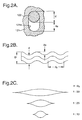
- Figures 2 A, B and C show the configuration of the stator and rotor.
- Figure 2A is a sketched partial cross-section of the rotor and stator. As shown, the rotor is circular in cross-section with a minor diameter, d.
- the bore in the stator is track shaped, i.e. has two semicircular ends joined by straight sides, in cross-section. Its long axis diameter is equal to the minor diameter of the rotor plus four times the eccentricity.
- Figure 2B is a sketch of part of the rotor. As shown, the major diameter, D, of the rotor is equal to the minor diameter, d, plus twice the eccentricity, e. The pitch of the rotor, as shown, is equal to the lead, p r .
- Figure 2 C is a sketch of capsulism profiles of progressing cavity pumps for different values of the ratio of eccentricity, e, to the stator lead, p s .
- typical progressing cavity pumps have a ratio of e:p s of between 1:25 and 1:50
- the ratio of eccentricity, e, to minor diameter of the rotor, d is 1:4.9
- the ratio of eccentricity, e, to stator lead, p s is 1:13.3.
- the pump may therefore be described as having a 1:4.9:13.3 ratio.
- Figure 3 is a graph showing power consumption in kiloWatts on axis Y vs. solids content of the pumped fluid on axis X.
- Line A is the pump of Figure 1 and lines B and C are prior art pumps of ratios 1:5:26 and 1:6:27 respectively.
- the pump of the present invention uses 12% less power than pump B and nearly 20% less than pump C.
- the described embodiment of the invention has two stages but pumps of more or fewer stages may also be constructed with the same geometry.
- the embodiment of Figure 1 is adapted to be mounted on a vehicle, such as a truck bearing reservoirs of explosive components to be mixed prior to pumping.
Landscapes
- Engineering & Computer Science (AREA)
- Mechanical Engineering (AREA)
- General Engineering & Computer Science (AREA)
- Rotary Pumps (AREA)
Description
- The present invention relates to progressing cavity pumps and particularly to such pumps suitable for pumping liquid/solid mixtures having a high proportion of relatively incompressible solids.
- In, for example, mining applications it is necessary to pump explosive mixtures having liquid and solid components from a truck carrying bulk supplies of the components to pre-drilled holes in the rock to be quarried or mined. Normally the solids content of the mixture is about 35-40% of the total, the remainder being liquid. It is desirable from a cost point of view to reduce the liquid content so that the mixture is about 50% solids. However, existing progressing cavity pumps have excessive power requirements when pumping mixtures of such high solids content and are prone to entrapment of solid material and stalling. Examples of such pumps are described in US 4,773,834, US 4,591,322, GB 1,542,786 and GB-A-2,228,976.
- According to the present invention there is provided a progressing cavity pump comprising a stator having a bore therethrough formed with a female, two start, helical gear formation of a given pitch, a cooperating rotor formed with a male, single start, helical gear formation of the same pitch and a drive arrangement for causing the rotor to rotate and orbit relative to the stator, wherein
the ratio of the eccentricity, e, of the gear formation of the rotor to its minor diameter, d, is in the range of between 1 to 4.6 and 1 to 5.2 and the ratio of the eccentricity, e, of the gear formation of the rotor to stator lead, ps, is in the range of between 1 to 11 and 1 to 15. - Preferably, the ratio of the eccentricity (e) of the rotor gear to its minor diameter (d) is in the range of from 1:4.8 to 1:5.0 and the ratio of the eccentricity (e) of the rotor gear to the stator lead (ps) is in the range of from 1:13 to 1:13.6. Ideally the ratio e:d is about 1:4.9 and the ratio e:ps is about 1:13.3.
- Pumps according to the present invention are able to pump liquid/solid mixtures with a solids content of about 50% with a reduced power requirement and a reduced risk of entrapment of solid material.
- Exemplary embodiments of the invention will be described below with reference to the accompanying drawings, in which:
- Fig. 1 is a part-sectional view of a progressing cavity pump according to a first embodiment of the present invention;
- Figs 2 A, B and C are sketches illustrating the parameters e, d and p; and
- Fig. 3 is a graph illustrating power requirement vs. solids ratio of the first embodiment of the invention and two known pumps.
-
- In the Figures, like parts are identified by like reference numerals.
- Figure 1 shows a first embodiment of a progressing
cavity pump 10 embodying the present invention. Thepump 10 has, as its major components,inlet chamber 11,pumping section 12,drive section 13 anddischarge section 14. It is driven by viainput shaft 15. - The
inlet chamber 11 has aninlet 111 for the mixture to be pumped and will have suitable fittings for direct connection to a reservoir of the mixture or appropriate supply conduits. -
Pumping section 12 comprises astator 121 androtor 122. Thestator 121 is a cylinder of compliant material, e.g. rubber, with an axial bore having a female, two start,helical gear surface 121a. Therotor 122 is an elongate rod with its outer surface machined to form a male, one start,helical gear 122a corresponding to thefemale gear surface 121a of the stator. The rotor may be made from stainless steel or carbon steel coated in hard chromium. Thehelical gear surfaces stator gear surface 121a has twice the eccentricity as therotor gear surface 122a. As thefemale gear 121a on the stator has two starts, its lead, ps, is twice the lead, pr, of themale gear 122a on the rotor. - Drive from the
input shaft 15, which may be via a hydraulic motor of known type, is transmitted to therotor 122 of thepumping section 12. Therotor 122 is driven to rotate and is caused to orbit by the interaction of the male and female gears. The orbiting motion is permitted by theelongate drive shaft 131 which has a certain degree of flexibility. The rotation and orbiting of the rotor relative to the stator causes cavities formed between the gears to progress from theinlet chamber 11 to theoutput 14. - Figures 2 A, B and C show the configuration of the stator and rotor. Figure 2A is a sketched partial cross-section of the rotor and stator. As shown, the rotor is circular in cross-section with a minor diameter, d. The bore in the stator is track shaped, i.e. has two semicircular ends joined by straight sides, in cross-section. Its long axis diameter is equal to the minor diameter of the rotor plus four times the eccentricity.
- Figure 2B is a sketch of part of the rotor. As shown, the major diameter, D, of the rotor is equal to the minor diameter, d, plus twice the eccentricity, e. The pitch of the rotor, as shown, is equal to the lead, pr.
- Figure 2 C is a sketch of capsulism profiles of progressing cavity pumps for different values of the ratio of eccentricity, e, to the stator lead, ps. Whilst typical progressing cavity pumps have a ratio of e:ps of between 1:25 and 1:50, in this embodiment of the present invention the ratio of eccentricity, e, to minor diameter of the rotor, d, is 1:4.9 and the ratio of eccentricity, e, to stator lead, ps, is 1:13.3. The pump may therefore be described as having a 1:4.9:13.3 ratio.
- Figure 3 is a graph showing power consumption in kiloWatts on axis Y vs. solids content of the pumped fluid on axis X. Line A is the pump of Figure 1 and lines B and C are prior art pumps of ratios 1:5:26 and 1:6:27 respectively. As can be seen the pump of the present invention uses 12% less power than pump B and nearly 20% less than pump C.
- The described embodiment of the invention has two stages but pumps of more or fewer stages may also be constructed with the same geometry.
- The embodiment of Figure 1 is adapted to be mounted on a vehicle, such as a truck bearing reservoirs of explosive components to be mixed prior to pumping.
Claims (6)
- A progressing cavity pump (12) comprising a stator having a bore (121) therethrough formed with a female, two start, helical gear formation (121a) of a given pitch (122), a cooperating rotor formed with a male, single start, helical gear formation (122a) of the same pitch and a drive arrangement (131) for causing the rotor (122) to rotate and orbit relative to the stator (121),
wherein the ratio of the eccentricity, (e) of the gear formation of the rotor to its minor diameter (d) is in the range of between 1 to 4.6 and 1 to 5.2 and characterised in that the ratio of the eccentricity (e) of the gear formation of the rotor to the stator lead (ps) is in the range of between 1 to 11 and 1 to 15. - A pump according to claim 1 wherein the ratio of said eccentricity to said minor diameter (e : d) is in the range of between 1 to 4.8 and 1 to 5.0 and the ratio of said eccentricity to said stator lead (e : ps) is in the range of between 1 to 13 and 1 to 13.6.
- A pump according to claim 1 wherein the ratio of said eccentricity to said minor diameter (e : d) is about 1:4.9 and the ratio of said eccentricity to said stator lead (e : ps) is about 13.3.
- A method of pumping explosive mixtures having liquid and solid components comprising the step of using a progressing cavity pump according to any one of the preceding claims.
- A method according to claim 4 wherein the total solids content of the mixture is greater than 45% by volume.
- A vehicle having mounted thereon reservoirs for storing components of an explosive mixture, means for mixing said components and a progressing cavity pump according to any one of claims 1 to 3 for pumping the mixed components.
Applications Claiming Priority (2)
| Application Number | Priority Date | Filing Date | Title |
|---|---|---|---|
| GB9819652 | 1998-09-09 | ||
| GB9819652A GB2341423B (en) | 1998-09-09 | 1998-09-09 | Progressing cavity pump |
Publications (2)
| Publication Number | Publication Date |
|---|---|
| EP0985826A1 EP0985826A1 (en) | 2000-03-15 |
| EP0985826B1 true EP0985826B1 (en) | 2005-05-18 |
Family
ID=10838581
Family Applications (1)
| Application Number | Title | Priority Date | Filing Date |
|---|---|---|---|
| EP99306771A Expired - Lifetime EP0985826B1 (en) | 1998-09-09 | 1999-08-26 | Progressing cavity pump |
Country Status (6)
| Country | Link |
|---|---|
| US (1) | US6220837B1 (en) |
| EP (1) | EP0985826B1 (en) |
| AU (1) | AU754641B2 (en) |
| CA (1) | CA2282017C (en) |
| DE (1) | DE69925346T2 (en) |
| GB (1) | GB2341423B (en) |
Families Citing this family (2)
| Publication number | Priority date | Publication date | Assignee | Title |
|---|---|---|---|---|
| DE202009002823U1 (en) * | 2009-03-02 | 2009-07-30 | Daunheimer, Ralf | Cavity Pump |
| EA039555B1 (en) * | 2020-10-20 | 2022-02-10 | Борис Иванович Уваров | Rotor of a single-screw gerotor pump |
Family Cites Families (10)
| Publication number | Priority date | Publication date | Assignee | Title |
|---|---|---|---|---|
| US2636834A (en) * | 1950-02-15 | 1953-04-28 | Byerlyte Corp | Asphaltic-composition application |
| DE1553146A1 (en) * | 1965-09-16 | 1970-02-05 | Netzsch Maschinenfabrik | Runner for screw pumps |
| US3503343A (en) * | 1967-04-21 | 1970-03-31 | Baker Res & Dev Service Inc | Method and apparatus for making continuous mix bread |
| FR2343906A1 (en) | 1976-03-09 | 1977-10-07 | Mecanique Metallurgie Ste Gle | IMPROVEMENTS TO SCREW PUMP STATORS |
| US4325682A (en) * | 1979-12-12 | 1982-04-20 | E. I. Du Pont De Nemours And Company | Apparatus for discharging material |
| CA1208072A (en) * | 1983-08-16 | 1986-07-22 | Minoru Saruwatari | Progressive cavity pump |
| KR850004305A (en) * | 1983-12-28 | 1985-07-11 | 오노 쓰네오 | Rotary Displacement Eccentric Archimedes Principle Screw Pump |
| US4614146A (en) * | 1984-05-14 | 1986-09-30 | Les Explosifs Nordex Ltee/Nordex Explosives Ltd. | Mix-delivery system for explosives |
| GB2228976B (en) * | 1989-02-01 | 1993-08-11 | Mono Pumps Ltd | Helical gear pump |
| DE4134853C1 (en) * | 1991-05-22 | 1992-11-12 | Netzsch-Mohnopumpen Gmbh, 8264 Waldkraiburg, De |
-
1998
- 1998-09-09 GB GB9819652A patent/GB2341423B/en not_active Revoked
-
1999
- 1999-08-26 EP EP99306771A patent/EP0985826B1/en not_active Expired - Lifetime
- 1999-08-26 DE DE69925346T patent/DE69925346T2/en not_active Expired - Lifetime
- 1999-08-31 AU AU44856/99A patent/AU754641B2/en not_active Expired
- 1999-09-02 US US09/387,385 patent/US6220837B1/en not_active Expired - Lifetime
- 1999-09-08 CA CA002282017A patent/CA2282017C/en not_active Expired - Lifetime
Also Published As
| Publication number | Publication date |
|---|---|
| GB2341423B (en) | 2002-04-24 |
| DE69925346D1 (en) | 2005-06-23 |
| DE69925346T2 (en) | 2006-01-19 |
| US6220837B1 (en) | 2001-04-24 |
| GB2341423A (en) | 2000-03-15 |
| CA2282017A1 (en) | 2000-03-09 |
| CA2282017C (en) | 2008-03-25 |
| AU4485699A (en) | 2000-03-16 |
| AU754641B2 (en) | 2002-11-21 |
| EP0985826A1 (en) | 2000-03-15 |
| GB9819652D0 (en) | 1998-11-04 |
Similar Documents
| Publication | Publication Date | Title |
|---|---|---|
| US11512695B2 (en) | External gear pump integrated with two independently driven prime movers | |
| US5171138A (en) | Composite stator construction for downhole drilling motors | |
| US6716008B1 (en) | Eccentric screw pump with expanded temperature range | |
| JPS63502292A (en) | Screw-shaped hydraulically operated excavation motor, method of manufacturing the same, and device for carrying out the same | |
| GB2454700A (en) | A progressive cavity device with drive connections at both ends. | |
| US7383898B2 (en) | Inner and outer motor with eccentric stabilizer | |
| EP0627557B1 (en) | Helical gear fluid machine | |
| CA2282017C (en) | Progressing cavity pump | |
| EP1503034B1 (en) | Gerotor type machine | |
| US4567953A (en) | Bottom-hole multistart screw motor | |
| CA2058080C (en) | Composite stator construction for downhole drilling motors | |
| RU55050U1 (en) | DEVICE FOR PUMPING GAS-LIQUID MIXTURES DURING TECHNOLOGICAL OPERATIONS IN WELLS | |
| GB2084254A (en) | Rotary Positive-displacement Fluid-machine | |
| KR20260032897A (en) | Reversible hydraulic machine with helical toothed gears provided with a two-way hydraulic system for axial force balance | |
| RU2232860C2 (en) | Gyrator hydraulic motor | |
| RU2094658C1 (en) | Two-screw pump | |
| US6524087B1 (en) | Hydrostatic planetary rotation machine having an orbiting rotary valve | |
| RU2247263C2 (en) | Helical rotor pump | |
| EP1130263A2 (en) | Helical gear vacuum pump | |
| TW353708B (en) | Hydrostatic drives | |
| GB2410304A (en) | Asymmetric thread profile with improved fatigue life | |
| JPS6038514B2 (en) | Multi-start screw type helical planetary gear motor for anti-bottom use | |
| CA2252685A1 (en) | Bending rod connection | |
| WO2007139438A3 (en) | Worm gerotor pump | |
| MXPA98009042A (en) | Flex vastago connection |
Legal Events
| Date | Code | Title | Description |
|---|---|---|---|
| PUAI | Public reference made under article 153(3) epc to a published international application that has entered the european phase |
Free format text: ORIGINAL CODE: 0009012 |
|
| AK | Designated contracting states |
Kind code of ref document: A1 Designated state(s): DE FR GB |
|
| AX | Request for extension of the european patent |
Free format text: AL;LT;LV;MK;RO;SI |
|
| 17P | Request for examination filed |
Effective date: 20000303 |
|
| AKX | Designation fees paid |
Free format text: DE FR GB |
|
| 17Q | First examination report despatched |
Effective date: 20031020 |
|
| GRAP | Despatch of communication of intention to grant a patent |
Free format text: ORIGINAL CODE: EPIDOSNIGR1 |
|
| GRAS | Grant fee paid |
Free format text: ORIGINAL CODE: EPIDOSNIGR3 |
|
| GRAA | (expected) grant |
Free format text: ORIGINAL CODE: 0009210 |
|
| AK | Designated contracting states |
Kind code of ref document: B1 Designated state(s): DE FR GB |
|
| REG | Reference to a national code |
Ref country code: GB Ref legal event code: FG4D |
|
| REF | Corresponds to: |
Ref document number: 69925346 Country of ref document: DE Date of ref document: 20050623 Kind code of ref document: P |
|
| ET | Fr: translation filed | ||
| PLBE | No opposition filed within time limit |
Free format text: ORIGINAL CODE: 0009261 |
|
| STAA | Information on the status of an ep patent application or granted ep patent |
Free format text: STATUS: NO OPPOSITION FILED WITHIN TIME LIMIT |
|
| 26N | No opposition filed |
Effective date: 20060221 |
|
| REG | Reference to a national code |
Ref country code: FR Ref legal event code: PLFP Year of fee payment: 18 |
|
| REG | Reference to a national code |
Ref country code: FR Ref legal event code: PLFP Year of fee payment: 19 |
|
| REG | Reference to a national code |
Ref country code: FR Ref legal event code: PLFP Year of fee payment: 20 |
|
| PGFP | Annual fee paid to national office [announced via postgrant information from national office to epo] |
Ref country code: FR Payment date: 20180712 Year of fee payment: 20 Ref country code: DE Payment date: 20180814 Year of fee payment: 20 |
|
| PGFP | Annual fee paid to national office [announced via postgrant information from national office to epo] |
Ref country code: GB Payment date: 20180822 Year of fee payment: 20 |
|
| REG | Reference to a national code |
Ref country code: DE Ref legal event code: R071 Ref document number: 69925346 Country of ref document: DE |
|
| REG | Reference to a national code |
Ref country code: GB Ref legal event code: PE20 Expiry date: 20190825 |
|
| PG25 | Lapsed in a contracting state [announced via postgrant information from national office to epo] |
Ref country code: GB Free format text: LAPSE BECAUSE OF EXPIRATION OF PROTECTION Effective date: 20190825 |