EP0985558A2 - Run-flat tyre - Google Patents
Run-flat tyre Download PDFInfo
- Publication number
- EP0985558A2 EP0985558A2 EP19990307078 EP99307078A EP0985558A2 EP 0985558 A2 EP0985558 A2 EP 0985558A2 EP 19990307078 EP19990307078 EP 19990307078 EP 99307078 A EP99307078 A EP 99307078A EP 0985558 A2 EP0985558 A2 EP 0985558A2
- Authority
- EP
- European Patent Office
- Prior art keywords
- radially
- ply
- tyre
- sidewall
- outside
- Prior art date
- Legal status (The legal status is an assumption and is not a legal conclusion. Google has not performed a legal analysis and makes no representation as to the accuracy of the status listed.)
- Granted
Links
Images


Classifications
-
- B—PERFORMING OPERATIONS; TRANSPORTING
- B60—VEHICLES IN GENERAL
- B60C—VEHICLE TYRES; TYRE INFLATION; TYRE CHANGING; CONNECTING VALVES TO INFLATABLE ELASTIC BODIES IN GENERAL; DEVICES OR ARRANGEMENTS RELATED TO TYRES
- B60C15/00—Tyre beads, e.g. ply turn-up or overlap
- B60C15/0009—Tyre beads, e.g. ply turn-up or overlap features of the carcass terminal portion
- B60C15/0036—Tyre beads, e.g. ply turn-up or overlap features of the carcass terminal portion with high ply turn-up, i.e. folded around the bead core and terminating radially above the point of maximum section width
- B60C15/0045—Tyre beads, e.g. ply turn-up or overlap features of the carcass terminal portion with high ply turn-up, i.e. folded around the bead core and terminating radially above the point of maximum section width with ply turn-up up to the belt edges, i.e. folded around the bead core and extending to the belt edges
-
- B—PERFORMING OPERATIONS; TRANSPORTING
- B60—VEHICLES IN GENERAL
- B60C—VEHICLE TYRES; TYRE INFLATION; TYRE CHANGING; CONNECTING VALVES TO INFLATABLE ELASTIC BODIES IN GENERAL; DEVICES OR ARRANGEMENTS RELATED TO TYRES
- B60C15/00—Tyre beads, e.g. ply turn-up or overlap
- B60C15/06—Flipper strips, fillers, or chafing strips and reinforcing layers for the construction of the bead
- B60C15/0603—Flipper strips, fillers, or chafing strips and reinforcing layers for the construction of the bead characterised by features of the bead filler or apex
- B60C15/0607—Flipper strips, fillers, or chafing strips and reinforcing layers for the construction of the bead characterised by features of the bead filler or apex comprising several parts, e.g. made of different rubbers
-
- B—PERFORMING OPERATIONS; TRANSPORTING
- B60—VEHICLES IN GENERAL
- B60C—VEHICLE TYRES; TYRE INFLATION; TYRE CHANGING; CONNECTING VALVES TO INFLATABLE ELASTIC BODIES IN GENERAL; DEVICES OR ARRANGEMENTS RELATED TO TYRES
- B60C17/00—Tyres characterised by means enabling restricted operation in damaged or deflated condition; Accessories therefor
- B60C17/0009—Tyres characterised by means enabling restricted operation in damaged or deflated condition; Accessories therefor comprising sidewall rubber inserts, e.g. crescent shaped inserts
Definitions
- the present invention relates to a pneumatic tyre, more particularly to a run-flat tyre having an improved sidewall reinforcing structure.
- a tyre which has a sidewall portion (s) reinforced with a relatively thick rubber layer (g) has been proposed, wherein this thick rubber layer (g) is disposed on the axially inside of the carcass to extend along the inside of the tyre.
- an object of the present invention to provide a run-flat tyre improved in run-flat performance, e.g. running distance, durability and the like without increasing the tyre weight and deteriorating running performance under normal conditions.
- a run-flat tyre comprises a tread portion, a pair of sidewall portions, a pair of bead portions each with a bead core therein, a carcass comprising an inner ply and an outer ply each made of organic fibre cords, a belt disposed radially outside the carcass in the tread portion, sidewall reinforcing rubber layers disposed in each said sidewall portion, each of the inner ply and outer ply extending between the bead portions through the tread portion and sidewall portions and turned up around the bead core in each bead portion from the inside to the outside of the tyre to form a pair of turnup portion and a main portion therebetween wherein the turnup portions of the inner ply extended to between the belt and the carcass and each having a radially outer end secured therebetween, the sidewall reinforcing rubber layers including an inside layer disposed axially inside the main portion of the inner ply; a middle layer disposed between the main portion of
- the thickness of the sidewall portion at a point at 75 % of the tyre section height is 1.0 to 1.2 times the thickness of the sidewall portion at the maximum tyre section width point.
- the total of the thicknesses of the inside layer, middle layer and outside layer is not less than 40 % of the thickness of the sidewall portion at a point at 75 % of the tyre section height.
- the outer end(s) of at least one, preferably two, more preferably three of the reinforcing rubber layers is(are) disposed in a region beneath the breaker belt. It is preferable that the inner end(s) of at least one, preferably two, more preferably three of the reinforcing rubber layers is(are) disposed in a region radially inwards of the maximum tyre section width point but radially outwards of the radially outside of the bead core, and it is more preferable that both the outer and inner ends of at least one of the reinforcing rubber layers are disposed in the above-mentioned two regions.
- the run-flat tyre 1 comprises a tread portion 2, a pair of sidewall portions 3, a pair of bead portions 4 each with a bead core 5 therein, a radial ply carcass 6, a belt 7, 10 disposed radially outside the carcass 6 in the tread portion 2, and sidewall reinforcing layers 9 disposed in each of the sidewall portions 3.
- the tyre 1 is mounted on its standard wheel rim J and inflated to standard inner pressure but loaded with no tyre load.
- the sizes or dimensions of the tyre are measured under this condition if not specifically mentioned.
- the standard rim is the "standard rim” specified in JATMA, the “Measuring Rim” in ETRTO, the “Design Rim” in TRA or the like.
- the standard pressure is the "maximum air pressure" in JATMA, the “Inflation Pressure” in ETRTO, the maximum pressure given in the "Tyre Load Limits at Various Cold Inflation Pressures" table in TRA or the like.
- the standard load is the "maximum load capacity" in JATMA, the “Load Capacity” in ETRTO, the maximum value given in the above-mentioned table in TRA or the like.
- the standard pressure 180 kPa is used.
- the carcass 6 comprises an inner ply 6A and an outer ply 6B each made of organic fibre cords.
- organic fibre cords rayon cords are used in this embodiment, but other materials such as polyester, nylon and the like can be used.
- the cords of each carcass ply are arranged radially at an angle of 75 to 90 degrees with respect to the tyre equator C so that the ply has a radial structure.
- the cord angle in each ply is the same value of about 88 degrees but the inclining directions are opposite with respect to the tyre equator C.
- the cords of one ply cross those of the other ply at a small angle of about 4 degrees in this example.
- the belt includes a breaker 7 and a band or bandage 10 disposed radially outside the breaker 7.
- the breaker 7 comprises two crossed plies 7A and 7B, each ply mace of parallel cords laid at an angle of from 10 to 35 degrees with respect to the tyre equator C.
- each ply is made of aramid cords laid at 22 degrees. Aside from aramid cords, steel cords and the like can be used.
- the band 10 is made of an organic fibre cord laid substantially parallel to the tyre circumferential direction.
- the band cords have a lower elastic modulus than the breaker cords.
- the band 10 is composed of a pair of axially spaced edge-band plies 10A covering the axial edges of the breaker 7 and a full-width band ply 10B disposed radially outside thereof and extending across the substantially full width of the breaker 7.
- each edge-band ply 10A has a width of about 10 to 20 % (in this example about 16%) of the axial width 3W of the breaker 7.
- Both the band plies 10A and 10B in this embodiment are formed by spirally winding a tape of rubber, in which parallel nylon cords are embedded along the length thereof.
- the above-mentioned carcass plies 6A and 6B extend between the bead portions through the tread portion and sidewall portions and are turned up around the bead core 5 in each bead portion from the inside to the outside of the tyre so that: the carcass ply 6A comprises a pair of turnup portions 6b1 and a main portion 6a1 therebetween; and the carcass ply 6B comprises a pair of turnup portions 6b2 and a main portion 6a2 therebetween.
- edges 6e of the turnup portions 6b1 of the inner ply 6A extend to between the carcass 6 and breaker 7, and the overlap 11 of the turnup portion 6b1 with the breaker 7 has an axial length L of from 3 to 8 % (in this embodiment about 6.5%) of the axial width BW of the breaker.
- the turnup portion 6b2 of the outer ply 6B has a height of about 0.4 to 0.6 times the tyre section height H (in this embodiment about 0.46 times) each from the bead base line BL. This means that the turnup end is positioned around the maximum tyre section width point M.
- the tyre section height H is the radial height measured from the bead base line BL to the radially outermost point.
- the bead base line is an axial line passing to a position corresponding to the rim diameter.
- a bead apex 12 is disposed between the turnup portion 6b2 and main portion 6a2 of the outer carcass ply 6B.
- the bead apex 12 is made of a hard rubber and extends and tapers radially outwardly from the outside 5a of the bead core 5.
- the above-mentioned sidewall reinforcing layers 9 include: an inside reinforcing rubber layer 9a disposed between the main portion 6a1 of the inner ply 6A and an air tight inner liner (i) disposed along the inside of the tyre; a middle reinforcing rubber layer 9b disposed between the main portions 6a1 and 6a2 of the inner and outer plies 6A and 6B; and an outside reinforcing rubber layer 9c disposed between the main portion 6a2 of the outer ply 6B and the turnup portions 6b1 and 6b2.
- Each of the reinforcing rubber layers 9a-9c tapers radially inwardly and radially outwardly.
- each layer (9a, 9b, 9c) has a radially outer end (9a1, 9b1, 9c1) located beneath, i.e. radially inwards of, the breaker 7 as shown in Fig.2, and a radially inner end (9a2, 9b2, 9c2) located radically inside the maximum tyre section width point M but radially outside the outer end 5a of the bead core 5.
- the outer ends 9a1, 9b1 and 9c1 are placed at different axial positions so that the total thickness of the layers gradually changes from the tread portion 2 to the sidewall portion 3.
- the outer end 9a1 is inmost, and the outer end 9c1 is outmost.
- the outer end 9bl is in the middle of the others.
- At least one of the radially inner ends 9a2, 9b2 and 9c2 of the reinforcing rubber layers 9a, 9b and 9c is positioned radially inwards of the maximum tyre section width point M. None of the radially inner ends 9a2, 9b2 and 9c2 is positioned radially inwards of the outer end 5a of the bead core 5.
- the radially inner tapered portion of the outside layer 9c and the radially outer tapered portion of the bead apex 12 are spliced, and in this spliced portion, the outside layer 9c is positioned axially outside the bead apex 12 and the radially inner end 9c2 thereof reaches near the radially outside of the bead core 5.
- the radially inner ends 9b2 and 9a2 of the middle and inside layers 9b and 9a reach to radially different positions which are radially inwards of the radially outer end of the bead apex 12 but radially outwards of the radially out end 5a of the bead core 5.
- the total thickness of the sidewall portion 3 is such that the total thickness S2 at a point B is set in the range of from 1.0 to 1.4 times, preferably more than 1.0 times but not more than 1.4 times, more preferably more than 1.0 times but not more than 1.2 times, still more preferably 1.1 to 1.2 times the total thickness S1 at the maximum tyre section width point M.
- the point B is a point on the outer surface of the tyre at a radial height of 75 % of the tyre section height H.
- the total thickness S1, S2 is measured along the normal direction to the outer surface or profile of the tyre.
- the total (a1+b1+c1) of the thicknesses a1, b1 and c1 of the layers 9a, 9b and 9c, respectively, is set to be not less than 50 %, preferably 50 to 70 %, more preferably 50 to 65 %, still more preferably 55 to 65 % of the total thickness S1.
- the total (a2+b2+c2) of the thicknesses a2, b2 and c2 of the layers 9a, 9b and 9c, respectively, is set to be not less than 40 %, preferably 45 to 60 % of the total thickness S2.
- the total (a2+b2+c2) is smaller than the total (a1+b1+c1).
- Each of the reinforcing rubber layers 9 is made of a rubber compound of low-heat-generation having a complex elastic modulus E* of from 7.0 to 12.0 MPa and a loss tangent (tan ⁇ ) of not more than 0.02, preferably not more than 0.01, more preferably in the range of from 0.008 to 0.001.
- all the layers 9a, 9b and 9c are made of the same rubber compound, but it is also possible to use different rubber compounds which satisfy
- the complex elastic modulus E* is outside the range of from 7.0 to 12.0 MPa, the bending rigidity of the sidewall portion 3 tends to decrease and heat generation increases and ride comfort deteriorates.
- Example tyres were remarkably increased in runable distance although the tyre weight was maintained at the same level as the Prior Art tyre.
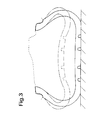
- Fig.3 shows cross-sections of the Embodiment tyre when loaded with 4.41 kN under normally inflated condition (solid line) and a flat condition (chain line). This shows that even when the tyre is punctured the Embodiment tyre can endure its load without parts of the inner surfaces touching.
Landscapes
- Engineering & Computer Science (AREA)
- Mechanical Engineering (AREA)
- Tires In General (AREA)
Abstract
Description
- The present invention relates to a pneumatic tyre, more particularly to a run-flat tyre having an improved sidewall reinforcing structure.
- In order to improve run-flat performance such as the run-flat distance of a pneumatic tyre, as shown in Fig.4, a tyre which has a sidewall portion (s) reinforced with a relatively thick rubber layer (g) has been proposed, wherein this thick rubber layer (g) is disposed on the axially inside of the carcass to extend along the inside of the tyre.
- In this reinforcing structure, however, under run-flat conditions, damage starting from the carcass ply turnup edge (f1) is liable to occur as the edge (f1) is positioned in the sidewall portion, especially when it is positioned around the maximum tyre section width point. Further, the rubber layer (g) has a maximum thickness at the maximum tyre section width point. Under flat conditions, however, bending deformation becomes larger in the tyre shoulder portion than the maximum tyre section width portion. In other words, the bending is deformation concentrated un the shoulder portion. Thus, in this structure, the tyre has a tendency to have a weak point in the shoulder portion.
- Such drawbacks may be eliminated by for example covering the edge (f1) with an additional carcass ply and increasing the thickness of the rubber layer (g) . However, other problems arise such as an increase in the tyre weight and deterioration of ride comfort and dynamic performance under normal conditions.
- It is therefore, an object of the present invention to provide a run-flat tyre improved in run-flat performance, e.g. running distance, durability and the like without increasing the tyre weight and deteriorating running performance under normal conditions.
- According to one aspect of the present invention a run-flat tyre comprises a tread portion, a pair of sidewall portions, a pair of bead portions each with a bead core therein, a carcass comprising an inner ply and an outer ply each made of organic fibre cords, a belt disposed radially outside the carcass in the tread portion, sidewall reinforcing rubber layers disposed in each said sidewall portion, each of the inner ply and outer ply extending between the bead portions through the tread portion and sidewall portions and turned up around the bead core in each bead portion from the inside to the outside of the tyre to form a pair of turnup portion and a main portion therebetween wherein the turnup portions of the inner ply extended to between the belt and the carcass and each having a radially outer end secured therebetween, the sidewall reinforcing rubber layers including an inside layer disposed axially inside the main portion of the inner ply; a middle layer disposed between the main portion of the inner ply and the main portion of the outer ply; and an outside layer disposed axially outside the main portion of the outer ply, at least one of the sidewall reinforcing rubber layers having a radially outer end located beneath the belt, at least one of the sidewall reinforcing rubber layers having a radially inner end located radially outward of the bead core but radially inwards of a maximum tyre section width point, at the maximum tyre section width point, the total of the thicknesses of the inside layer, middle layer and outside layer being not less than 50 % of the thickness of the sidewall portion.
- Preferably, the thickness of the sidewall portion at a point at 75 % of the tyre section height is 1.0 to 1.2 times the thickness of the sidewall portion at the maximum tyre section width point. The total of the thicknesses of the inside layer, middle layer and outside layer is not less than 40 % of the thickness of the sidewall portion at a point at 75 % of the tyre section height.
- Further, it is preferable that the outer end(s) of at least one, preferably two, more preferably three of the reinforcing rubber layers is(are) disposed in a region beneath the breaker belt. It is preferable that the inner end(s) of at least one, preferably two, more preferably three of the reinforcing rubber layers is(are) disposed in a region radially inwards of the maximum tyre section width point but radially outwards of the radially outside of the bead core, and it is more preferable that both the outer and inner ends of at least one of the reinforcing rubber layers are disposed in the above-mentioned two regions.
- An embodiment of the present invention will now be described in detail in conjunction with the accompanying drawings:
- Fig.1 is a cross sectional view of an embodiment of the present invention;
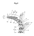
- Fig.2 is an enlarged cross sectional view of a shoulder portion thereof;
- Fig.3 shows cross sections of the tyre under a normal condition and a flat condition obtained by a CT scanner; and
- Fig.4 is a cross sectional view of a prior art tyre.
-
- In the drawings, the run-
flat tyre 1 according to the present invention comprises atread portion 2, a pair of sidewall portions 3, a pair ofbead portions 4 each with abead core 5 therein, aradial ply carcass 6, abelt carcass 6 in thetread portion 2, and sidewall reinforcing layers 9 disposed in each of the sidewall portions 3. - In Fig.1, the
tyre 1 is mounted on its standard wheel rim J and inflated to standard inner pressure but loaded with no tyre load. The sizes or dimensions of the tyre are measured under this condition if not specifically mentioned. Here, the standard rim is the "standard rim" specified in JATMA, the "Measuring Rim" in ETRTO, the "Design Rim" in TRA or the like. The standard pressure is the "maximum air pressure" in JATMA, the "Inflation Pressure" in ETRTO, the maximum pressure given in the "Tyre Load Limits at Various Cold Inflation Pressures" table in TRA or the like. The standard load is the "maximum load capacity" in JATMA, the "Load Capacity" in ETRTO, the maximum value given in the above-mentioned table in TRA or the like. In case of passenger car tyres, however, as the standard pressure, 180 kPa is used. - The
carcass 6 comprises aninner ply 6A and anouter ply 6B each made of organic fibre cords. For the organic fibre cords, rayon cords are used in this embodiment, but other materials such as polyester, nylon and the like can be used. The cords of each carcass ply are arranged radially at an angle of 75 to 90 degrees with respect to the tyre equator C so that the ply has a radial structure. In this embodiment, the cord angle in each ply is the same value of about 88 degrees but the inclining directions are opposite with respect to the tyre equator C. Thus, the cords of one ply cross those of the other ply at a small angle of about 4 degrees in this example. - The belt includes a
breaker 7 and a band orbandage 10 disposed radially outside thebreaker 7. - The
breaker 7 comprises twocrossed plies 7A and 7B, each ply mace of parallel cords laid at an angle of from 10 to 35 degrees with respect to the tyre equator C. In this embodiment, each ply is made of aramid cords laid at 22 degrees. Aside from aramid cords, steel cords and the like can be used. - The
band 10 is made of an organic fibre cord laid substantially parallel to the tyre circumferential direction. The band cords have a lower elastic modulus than the breaker cords. - In this embodiment, the
band 10 is composed of a pair of axially spaced edge-band plies 10A covering the axial edges of thebreaker 7 and a full-width band ply 10B disposed radially outside thereof and extending across the substantially full width of thebreaker 7. - Preferably, each edge-
band ply 10A has a width of about 10 to 20 % (in this example about 16%) of the axial width 3W of thebreaker 7. - Both the band plies 10A and 10B in this embodiment are formed by spirally winding a tape of rubber, in which parallel nylon cords are embedded along the length thereof.
- By using such a
spiral band 10, it becomes possible to effectively prevent ply separation failure even if thetread portion 2 warps as shown in Fig.3 by a chain line. Thus, the durability under run-flat condition can be improved. - According to the present invention, the above-mentioned
carcass plies bead core 5 in each bead portion from the inside to the outside of the tyre so that: thecarcass ply 6A comprises a pair of turnup portions 6b1 and a main portion 6a1 therebetween; and thecarcass ply 6B comprises a pair of turnup portions 6b2 and a main portion 6a2 therebetween. - The
edges 6e of the turnup portions 6b1 of theinner ply 6A extend to between thecarcass 6 andbreaker 7, and theoverlap 11 of the turnup portion 6b1 with thebreaker 7 has an axial length L of from 3 to 8 % (in this embodiment about 6.5%) of the axial width BW of the breaker. - The turnup portion 6b2 of the
outer ply 6B has a height of about 0.4 to 0.6 times the tyre section height H (in this embodiment about 0.46 times) each from the bead base line BL. This means that the turnup end is positioned around the maximum tyre section width point M. - Incidentally, the tyre section height H is the radial height measured from the bead base line BL to the radially outermost point. The bead base line is an axial line passing to a position corresponding to the rim diameter.
- In each of the above-mentioned
bead portions 4, abead apex 12 is disposed between the turnup portion 6b2 and main portion 6a2 of theouter carcass ply 6B. Thebead apex 12 is made of a hard rubber and extends and tapers radially outwardly from the outside 5a of thebead core 5. - The above-mentioned sidewall reinforcing layers 9 include: an inside reinforcing
rubber layer 9a disposed between the main portion 6a1 of theinner ply 6A and an air tight inner liner (i) disposed along the inside of the tyre; a middle reinforcing rubber layer 9b disposed between the main portions 6a1 and 6a2 of the inner andouter plies outer ply 6B and the turnup portions 6b1 and 6b2. Each of the reinforcingrubber layers 9a-9c tapers radially inwardly and radially outwardly. - In this embodiment, each layer (9a, 9b, 9c) has a radially outer end (9a1, 9b1, 9c1) located beneath, i.e. radially inwards of, the
breaker 7 as shown in Fig.2, and a radially inner end (9a2, 9b2, 9c2) located radically inside the maximum tyre section width point M but radially outside theouter end 5a of thebead core 5. - The outer ends 9a1, 9b1 and 9c1 are placed at different axial positions so that the total thickness of the layers gradually changes from the
tread portion 2 to the sidewall portion 3. In this embodiment, the outer end 9a1 is inmost, and the outer end 9c1 is outmost. Thus, the outer end 9bl is in the middle of the others. - At least one of the radially inner ends 9a2, 9b2 and 9c2 of the reinforcing
rubber layers 9a, 9b and 9c is positioned radially inwards of the maximum tyre section width point M. None of the radially inner ends 9a2, 9b2 and 9c2 is positioned radially inwards of theouter end 5a of thebead core 5. - In this embodiment shown in Fig.1, the radially inner tapered portion of the outside layer 9c and the radially outer tapered portion of the
bead apex 12 are spliced, and in this spliced portion, the outside layer 9c is positioned axially outside thebead apex 12 and the radially inner end 9c2 thereof reaches near the radially outside of thebead core 5. - On the other hand, the radially inner ends 9b2 and 9a2 of the middle and inside
layers 9b and 9a reach to radially different positions which are radially inwards of the radially outer end of thebead apex 12 but radially outwards of the radially outend 5a of thebead core 5. - As shown in Fig.2, the total thickness of the sidewall portion 3 is such that the total thickness S2 at a point B is set in the range of from 1.0 to 1.4 times, preferably more than 1.0 times but not more than 1.4 times, more preferably more than 1.0 times but not more than 1.2 times, still more preferably 1.1 to 1.2 times the total thickness S1 at the maximum tyre section width point M.
- The point B is a point on the outer surface of the tyre at a radial height of 75 % of the tyre section height H. The total thickness S1, S2 is measured along the normal direction to the outer surface or profile of the tyre.
- At the maximum tyre section width point M, the total (a1+b1+c1) of the thicknesses a1, b1 and c1 of the
layers 9a, 9b and 9c, respectively, is set to be not less than 50 %, preferably 50 to 70 %, more preferably 50 to 65 %, still more preferably 55 to 65 % of the total thickness S1. - Further, at the above-mentioned point B, the total (a2+b2+c2) of the thicknesses a2, b2 and c2 of the
layers 9a, 9b and 9c, respectively, is set to be not less than 40 %, preferably 45 to 60 % of the total thickness S2. - Preferably, the total (a2+b2+c2) is smaller than the total (a1+b1+c1).
- At the maximum tyre section width point M, it is preferable that the
layers 9a, 9b and 9c are substantially the same thickness (a1=b1=c1). But, the following relationships may be possible: a1<b1<c1 ; a1>b1>c1 ; a1>b1<c1 ; a1<b1>c1. - Each of the reinforcing rubber layers 9 is made of a rubber compound of low-heat-generation having a complex elastic modulus E* of from 7.0 to 12.0 MPa and a loss tangent (tan δ) of not more than 0.02, preferably not more than 0.01, more preferably in the range of from 0.008 to 0.001.
- In this embodiment, all the
layers 9a, 9b and 9c are made of the same rubber compound, but it is also possible to use different rubber compounds which satisfy - E*a>E*b>E*c or
- E*a<E*b<E*c or
- E*a<E*b>E*c or
- E*a>E*b<E*c, wherein E*a, E*b and E*c are the complex elastic moduli of the
-
- If the complex elastic modulus E* is outside the range of from 7.0 to 12.0 MPa, the bending rigidity of the sidewall portion 3 tends to decrease and heat generation increases and ride comfort deteriorates.
- If the loss tangent (tan δ) is more than 0.02, heat generation increases and the sidewall is liable to be broken by built-up heat.
- Running speed:
- 100 km/h (straight), 50 km/h (150R and 110R corners)
- Rim size:
- 16X7JJ (standard rim)
- Tyre load:
- 580 kgf
- The results are indicated by an index based on the Prior Art tyre being 100. The larger the index, the longer the runable distance.
- From the test results, it was confirmed that the Example tyres were remarkably increased in runable distance although the tyre weight was maintained at the same level as the Prior Art tyre.
- Fig.3 shows cross-sections of the Embodiment tyre when loaded with 4.41 kN under normally inflated condition (solid line) and a flat condition (chain line). This shows that even when the tyre is punctured the Embodiment tyre can endure its load without parts of the inner surfaces touching.
Tyre Prior Ex.1 Ex.2 Ref. Ex.3 Ex.4 Fig.4 Fig.1 Fig. 1 Fig. 1 Fig. 1 Fig. 1 Carcass cord rayon 1840 dtex/2 Breaker cord aramid 1670 dtex/2 Band cord nylon 1400 dtex/2 Reinforcing rubber layers
Complex elastic modulus
Loss tangent9.2 MPa inside=middle=outside= 9.2 MPa 0.005 inside=middle=outside= 0.005 S1 (mm) 20 18 18 15 18 18 a1+b1+c1 (mm) - 10 10 7 10 10 (a1+b1+c1)/S1 - 0.56 0.56 0.46 0.56 0.56 S2 (mm) 18 20 17 17 20 24 a2+b2+c2 (mm) - 9 7 7 7 12 (a2+b2+c2)/S2 - 0.45 0.41 0.41 0.35 0.5 S2/S1 0.9 1.11 0.94 1.13 1.11 1.33 Run-flat performance 100 300 100 50 150 400 Tyre weight 100 100 95 80 100 110
Claims (4)
Applications Claiming Priority (2)
| Application Number | Priority Date | Filing Date | Title |
|---|---|---|---|
| JP25424398 | 1998-09-08 | ||
| JP25424398A JP3007882B1 (en) | 1998-09-08 | 1998-09-08 | Run flat tire |
Publications (3)
| Publication Number | Publication Date |
|---|---|
| EP0985558A2 true EP0985558A2 (en) | 2000-03-15 |
| EP0985558A3 EP0985558A3 (en) | 2001-05-16 |
| EP0985558B1 EP0985558B1 (en) | 2004-04-14 |
Family
ID=17262275
Family Applications (1)
| Application Number | Title | Priority Date | Filing Date |
|---|---|---|---|
| EP19990307078 Expired - Lifetime EP0985558B1 (en) | 1998-09-08 | 1999-09-07 | Run-flat tyre |
Country Status (4)
| Country | Link |
|---|---|
| US (1) | US6196289B1 (en) |
| EP (1) | EP0985558B1 (en) |
| JP (1) | JP3007882B1 (en) |
| DE (1) | DE69916386T2 (en) |
Cited By (6)
| Publication number | Priority date | Publication date | Assignee | Title |
|---|---|---|---|---|
| EP1052117A3 (en) * | 1999-05-06 | 2001-03-07 | Dunlop Tire Corporation | Improvements to tyres |
| EP1186450A2 (en) * | 2000-09-08 | 2002-03-13 | Sumitomo Rubber Industries Ltd. | Runflat tire |
| EP1388436A1 (en) * | 2002-08-09 | 2004-02-11 | The Goodyear Tire & Rubber Company | Ruflat tire having sidewall thickness for optimized ride comfort |
| EP1481822A1 (en) * | 2003-05-30 | 2004-12-01 | Sumitomo Rubber Industries Limited | Pneumatic radial tire |
| US6834696B1 (en) | 2000-06-29 | 2004-12-28 | Bridgestone/Firestone North American Tire, Llc | Runflat tire with cantilever-like sidewall construction |
| US7703493B2 (en) | 2003-12-30 | 2010-04-27 | Michelin Recherche Et Technique S.A. | Tyre having asymmetrical self-supporting sidewalls |
Families Citing this family (14)
| Publication number | Priority date | Publication date | Assignee | Title |
|---|---|---|---|---|
| DE19860362A1 (en) * | 1998-12-24 | 2000-06-29 | Dunlop Gmbh | Pneumatic vehicle tires |
| US7546862B2 (en) * | 2005-05-06 | 2009-06-16 | New Tech Tire Llc | Non-pneumatic vehicle tire |
| EP1564031B1 (en) * | 2004-02-17 | 2008-03-12 | Sumitomo Rubber Industries, Ltd. | Side-reinforcing rubber composition and run flat tire using the same |
| JP3977817B2 (en) * | 2004-03-16 | 2007-09-19 | 住友ゴム工業株式会社 | Run flat tire |
| JP4653556B2 (en) * | 2005-05-13 | 2011-03-16 | 住友ゴム工業株式会社 | Run-flat tire and vehicle using the same |
| KR101472597B1 (en) * | 2008-08-07 | 2014-12-15 | 스미도모 고무 고교 가부시기가이샤 | Tire |
| US8672006B2 (en) | 2011-07-15 | 2014-03-18 | New Tech Tire Llc | Non-pneumatic tire |
| JP6295133B2 (en) | 2014-04-24 | 2018-03-14 | 東洋ゴム工業株式会社 | Run flat tire |
| JP6324815B2 (en) | 2014-05-30 | 2018-05-16 | 東洋ゴム工業株式会社 | Run-flat tire and manufacturing method thereof |
| JP6240562B2 (en) | 2014-06-10 | 2017-11-29 | 東洋ゴム工業株式会社 | Run flat tire |
| JP6227493B2 (en) * | 2014-07-14 | 2017-11-08 | 東洋ゴム工業株式会社 | Run flat tire |
| JP6342254B2 (en) | 2014-08-01 | 2018-06-13 | 東洋ゴム工業株式会社 | Run flat tire |
| JP6177282B2 (en) * | 2015-06-29 | 2017-08-09 | 住友ゴム工業株式会社 | Pneumatic tire |
| CN112078306A (en) * | 2020-08-07 | 2020-12-15 | 山东玲珑轮胎股份有限公司 | Tire and belted layer design structure |
Citations (6)
| Publication number | Priority date | Publication date | Assignee | Title |
|---|---|---|---|---|
| US3994329A (en) * | 1974-05-24 | 1976-11-30 | Pneumatiques, Caoutchouc Manufacture Et Plastiques Kleber-Colombes | Safety tire for vehicles |
| GB2087805A (en) * | 1980-11-24 | 1982-06-03 | Goodyear Tire & Rubber | Pneumatic safety tire |
| US5511599A (en) * | 1994-01-18 | 1996-04-30 | Michelin Recherche Et Technique S.A. | Run-flat tire with three crescent-shaped reinforcing members |
| EP0822105A2 (en) * | 1996-08-02 | 1998-02-04 | Michelin Recherche Et Technique S.A. | Run flat tire and method of manufacture |
| US6026878A (en) * | 1997-05-29 | 2000-02-22 | The Goodyear Tire & Rubber Company | Inextensible high temperature resistant tire |
| DE19845724A1 (en) * | 1998-10-05 | 2000-04-06 | Dunlop Gmbh | Pneumatic vehicle tires |
Family Cites Families (1)
| Publication number | Priority date | Publication date | Assignee | Title |
|---|---|---|---|---|
| US5871602A (en) * | 1997-05-29 | 1999-02-16 | The Goodyear Tire & Rubber Company | Tire with carcass turn up ends under belt structure |
-
1998
- 1998-09-08 JP JP25424398A patent/JP3007882B1/en not_active Expired - Fee Related
-
1999
- 1999-09-07 EP EP19990307078 patent/EP0985558B1/en not_active Expired - Lifetime
- 1999-09-07 DE DE1999616386 patent/DE69916386T2/en not_active Expired - Fee Related
- 1999-09-08 US US09/391,672 patent/US6196289B1/en not_active Expired - Fee Related
Patent Citations (7)
| Publication number | Priority date | Publication date | Assignee | Title |
|---|---|---|---|---|
| US3994329A (en) * | 1974-05-24 | 1976-11-30 | Pneumatiques, Caoutchouc Manufacture Et Plastiques Kleber-Colombes | Safety tire for vehicles |
| GB2087805A (en) * | 1980-11-24 | 1982-06-03 | Goodyear Tire & Rubber | Pneumatic safety tire |
| US5511599A (en) * | 1994-01-18 | 1996-04-30 | Michelin Recherche Et Technique S.A. | Run-flat tire with three crescent-shaped reinforcing members |
| EP0822105A2 (en) * | 1996-08-02 | 1998-02-04 | Michelin Recherche Et Technique S.A. | Run flat tire and method of manufacture |
| US6026878A (en) * | 1997-05-29 | 2000-02-22 | The Goodyear Tire & Rubber Company | Inextensible high temperature resistant tire |
| EP0984867A1 (en) * | 1997-05-29 | 2000-03-15 | The Goodyear Tire & Rubber Company | An inextensible high temperature resistant runflat tire |
| DE19845724A1 (en) * | 1998-10-05 | 2000-04-06 | Dunlop Gmbh | Pneumatic vehicle tires |
Cited By (10)
| Publication number | Priority date | Publication date | Assignee | Title |
|---|---|---|---|---|
| EP1052117A3 (en) * | 1999-05-06 | 2001-03-07 | Dunlop Tire Corporation | Improvements to tyres |
| US6834696B1 (en) | 2000-06-29 | 2004-12-28 | Bridgestone/Firestone North American Tire, Llc | Runflat tire with cantilever-like sidewall construction |
| EP1186450A2 (en) * | 2000-09-08 | 2002-03-13 | Sumitomo Rubber Industries Ltd. | Runflat tire |
| EP1186450A3 (en) * | 2000-09-08 | 2003-04-16 | Sumitomo Rubber Industries Ltd. | Runflat tire |
| US6609550B2 (en) | 2000-09-08 | 2003-08-26 | Sumitomo Rubber Industries, Ltd. | Runflat tire with steel cord bead reinforcing layer |
| EP1388436A1 (en) * | 2002-08-09 | 2004-02-11 | The Goodyear Tire & Rubber Company | Ruflat tire having sidewall thickness for optimized ride comfort |
| EP1481822A1 (en) * | 2003-05-30 | 2004-12-01 | Sumitomo Rubber Industries Limited | Pneumatic radial tire |
| CN1311992C (en) * | 2003-05-30 | 2007-04-25 | 住友橡胶工业株式会社 | Pneumatic radial tire |
| US7308924B2 (en) | 2003-05-30 | 2007-12-18 | Sumitomo Rubber Industries, Ltd. | Pneumatic radial tire |
| US7703493B2 (en) | 2003-12-30 | 2010-04-27 | Michelin Recherche Et Technique S.A. | Tyre having asymmetrical self-supporting sidewalls |
Also Published As
| Publication number | Publication date |
|---|---|
| US6196289B1 (en) | 2001-03-06 |
| EP0985558B1 (en) | 2004-04-14 |
| DE69916386T2 (en) | 2005-05-04 |
| EP0985558A3 (en) | 2001-05-16 |
| JP3007882B1 (en) | 2000-02-07 |
| JP2000085324A (en) | 2000-03-28 |
| DE69916386D1 (en) | 2004-05-19 |
Similar Documents
| Publication | Publication Date | Title |
|---|---|---|
| EP0985558B1 (en) | Run-flat tyre | |
| US7409974B2 (en) | Self-supporting pneumatic tire with a partial inner liner | |
| EP0206679B1 (en) | Reinforced bead structure for heavy duty tyre | |
| EP0985557B1 (en) | Run-flat tyre | |
| US6701986B2 (en) | Run-flat tire with tread reinforcing rubber layer | |
| US6527025B1 (en) | Tubeless tire | |
| EP0949091B1 (en) | Pneumatic tyre | |
| US20080006359A1 (en) | Runflat tire | |
| EP0911188B1 (en) | Run-flat tyre | |
| US5441093A (en) | Motorcycle radial tire with folded breaker ply and spirally wound band ply | |
| US6478064B1 (en) | Heavy duty radial tire with chafer height greater than bead apex height | |
| EP0850788B1 (en) | Pneumatic radial tyre | |
| EP1792752B1 (en) | Pneumatic radial tire for small-sized truck | |
| EP1197354B1 (en) | Pneumatic tire | |
| EP2261060B1 (en) | Motorcycle tire | |
| US6736178B2 (en) | Pneumatic tire with specified bead portion | |
| EP1186450B1 (en) | Runflat tire | |
| CA2012730C (en) | Pneumatic radial tire | |
| US6701987B1 (en) | Tread stiffening support ribs for runflat tire | |
| US6145560A (en) | Heavy duty pneumatic radial tires with specified belt cushion rubbers | |
| US6655431B2 (en) | Pneumatic tire with turnup portion wrapped along outer peripheral face of bead core | |
| EP3900954B1 (en) | Pneumatic tyre | |
| EP1171320B1 (en) | Tread stiffening support ribs for runflat tire |
Legal Events
| Date | Code | Title | Description |
|---|---|---|---|
| PUAI | Public reference made under article 153(3) epc to a published international application that has entered the european phase |
Free format text: ORIGINAL CODE: 0009012 |
|
| AK | Designated contracting states |
Kind code of ref document: A2 Designated state(s): DE FR GB |
|
| AX | Request for extension of the european patent |
Free format text: AL;LT;LV;MK;RO;SI |
|
| PUAL | Search report despatched |
Free format text: ORIGINAL CODE: 0009013 |
|
| AK | Designated contracting states |
Kind code of ref document: A3 Designated state(s): AT BE CH CY DE DK ES FI FR GB GR IE IT LI LU MC NL PT SE |
|
| AX | Request for extension of the european patent |
Free format text: AL;LT;LV;MK;RO;SI |
|
| 17P | Request for examination filed |
Effective date: 20011025 |
|
| AKX | Designation fees paid |
Free format text: DE FR GB |
|
| 17Q | First examination report despatched |
Effective date: 20021122 |
|
| GRAP | Despatch of communication of intention to grant a patent |
Free format text: ORIGINAL CODE: EPIDOSNIGR1 |
|
| GRAS | Grant fee paid |
Free format text: ORIGINAL CODE: EPIDOSNIGR3 |
|
| GRAA | (expected) grant |
Free format text: ORIGINAL CODE: 0009210 |
|
| AK | Designated contracting states |
Kind code of ref document: B1 Designated state(s): DE FR GB |
|
| REG | Reference to a national code |
Ref country code: GB Ref legal event code: FG4D |
|
| REF | Corresponds to: |
Ref document number: 69916386 Country of ref document: DE Date of ref document: 20040519 Kind code of ref document: P |
|
| ET | Fr: translation filed | ||
| PLBE | No opposition filed within time limit |
Free format text: ORIGINAL CODE: 0009261 |
|
| STAA | Information on the status of an ep patent application or granted ep patent |
Free format text: STATUS: NO OPPOSITION FILED WITHIN TIME LIMIT |
|
| 26N | No opposition filed |
Effective date: 20050117 |
|
| PGFP | Annual fee paid to national office [announced via postgrant information from national office to epo] |
Ref country code: GB Payment date: 20070905 Year of fee payment: 9 |
|
| PGFP | Annual fee paid to national office [announced via postgrant information from national office to epo] |
Ref country code: FR Payment date: 20080915 Year of fee payment: 10 |
|
| PGFP | Annual fee paid to national office [announced via postgrant information from national office to epo] |
Ref country code: DE Payment date: 20080919 Year of fee payment: 10 |
|
| GBPC | Gb: european patent ceased through non-payment of renewal fee |
Effective date: 20080907 |
|
| PG25 | Lapsed in a contracting state [announced via postgrant information from national office to epo] |
Ref country code: GB Free format text: LAPSE BECAUSE OF NON-PAYMENT OF DUE FEES Effective date: 20080907 |
|
| REG | Reference to a national code |
Ref country code: FR Ref legal event code: ST Effective date: 20100531 |
|
| PG25 | Lapsed in a contracting state [announced via postgrant information from national office to epo] |
Ref country code: FR Free format text: LAPSE BECAUSE OF NON-PAYMENT OF DUE FEES Effective date: 20090930 Ref country code: DE Free format text: LAPSE BECAUSE OF NON-PAYMENT OF DUE FEES Effective date: 20100401 |