EP0985485B1 - Laser welding machine for the welding of sections in large structural components - Google Patents
Laser welding machine for the welding of sections in large structural components Download PDFInfo
- Publication number
- EP0985485B1 EP0985485B1 EP99306618A EP99306618A EP0985485B1 EP 0985485 B1 EP0985485 B1 EP 0985485B1 EP 99306618 A EP99306618 A EP 99306618A EP 99306618 A EP99306618 A EP 99306618A EP 0985485 B1 EP0985485 B1 EP 0985485B1
- Authority
- EP
- European Patent Office
- Prior art keywords
- component
- laser welding
- welding machine
- head
- machine according
- Prior art date
- Legal status (The legal status is an assumption and is not a legal conclusion. Google has not performed a legal analysis and makes no representation as to the accuracy of the status listed.)
- Expired - Lifetime
Links
Images





Classifications
-
- B—PERFORMING OPERATIONS; TRANSPORTING
- B23—MACHINE TOOLS; METAL-WORKING NOT OTHERWISE PROVIDED FOR
- B23K—SOLDERING OR UNSOLDERING; WELDING; CLADDING OR PLATING BY SOLDERING OR WELDING; CUTTING BY APPLYING HEAT LOCALLY, e.g. FLAME CUTTING; WORKING BY LASER BEAM
- B23K26/00—Working by laser beam, e.g. welding, cutting or boring
- B23K26/08—Devices involving relative movement between laser beam and workpiece
- B23K26/10—Devices involving relative movement between laser beam and workpiece using a fixed support, i.e. involving moving the laser beam
-
- B—PERFORMING OPERATIONS; TRANSPORTING
- B23—MACHINE TOOLS; METAL-WORKING NOT OTHERWISE PROVIDED FOR
- B23K—SOLDERING OR UNSOLDERING; WELDING; CLADDING OR PLATING BY SOLDERING OR WELDING; CUTTING BY APPLYING HEAT LOCALLY, e.g. FLAME CUTTING; WORKING BY LASER BEAM
- B23K26/00—Working by laser beam, e.g. welding, cutting or boring
- B23K26/02—Positioning or observing the workpiece, e.g. with respect to the point of impact; Aligning, aiming or focusing the laser beam
- B23K26/035—Aligning the laser beam
- B23K26/037—Aligning the laser beam by pressing on the workpiece, e.g. using a pressing roller foot
-
- B—PERFORMING OPERATIONS; TRANSPORTING
- B23—MACHINE TOOLS; METAL-WORKING NOT OTHERWISE PROVIDED FOR
- B23K—SOLDERING OR UNSOLDERING; WELDING; CLADDING OR PLATING BY SOLDERING OR WELDING; CUTTING BY APPLYING HEAT LOCALLY, e.g. FLAME CUTTING; WORKING BY LASER BEAM
- B23K26/00—Working by laser beam, e.g. welding, cutting or boring
- B23K26/08—Devices involving relative movement between laser beam and workpiece
- B23K26/0869—Devices involving movement of the laser head in at least one axial direction
- B23K26/0876—Devices involving movement of the laser head in at least one axial direction in at least two axial directions
- B23K26/0884—Devices involving movement of the laser head in at least one axial direction in at least two axial directions in at least three axial directions, e.g. manipulators, robots
Definitions
- the invention relates to a laser welding machine for the welding of sections in large structural components, especially aluminium spars to curved, cylindrical or spherical aluminium skin sheets in aircraft construction, as defined in the pre-characterizing portion of claim 1.
- a laser welding machine is known from EP-A-0 838 301.
- the spars are attached to the inner side of the structures, providing strength to the skin sheets. Hitherto spars have been riveted to the skin sheet, and because of this the spars have an inverted "T" cross-section through the base of which the rivets pass.
- the known welding jig for the bilateral and simultaneous welding of spars to a skin sheet includes among other things a variable beam/support on which the skin sheet is placed and a flexible tensioning system using roller guides for precise positioning and fixing the spars on the skin sheet during a welding process.
- a pair of rollers which precede the laser beam and another positioned behind are provided in relation to the lateral guide for a spar.
- Each pair of rollers comprises a guide roller for determining the position of the spar and a tensioning roller.
- the spar is positioned by the mechanised head, which is driven by a digital control program which is orientated through fixed points to the actual position of the skin sheet.
- US-A-4,223,201 discloses an automated welding facility for the fabrication of shell sections suitable for ship construction and utilizing laser welding.
- the purpose of the invention is to provide a welding machine of the type indicated at the outset which makes automated high precision laser welding, preferably for aluminium sections to aluminium skin sheets in aircraft construction, possible.
- the subject matter of this invention is a laser welding machine, shown diagrammatically and in accordance with a possible embodiment in Figure 1, in which it will be seen that two laser or resonator units (1 and 2) mounted on a frame (6) are located on a portal commonly known as a gantry (3) in such a way that through the movements of gantry (3) frame (6) and with it resonators (1 and 2) can move along the X,Y,Z axes.
- Head (7) of the welding machine hangs from gantry (3) and in the non-restrictive example in Figure 1 is carrying out a welding process in which aluminium sections (5) known commonly as "stringers" are being welded to a curved aluminium sheet (4) belonging to the fuselage of an aircraft so that the two welding beams from the resonators (1 and 2) weld the two sides of stringers (5) in a single pass.
- stringers aluminium sections (5) known commonly as "stringers” are being welded to a curved aluminium sheet (4) belonging to the fuselage of an aircraft so that the two welding beams from the resonators (1 and 2) weld the two sides of stringers (5) in a single pass.
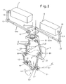
- Figure 2 provides a diagrammatical representation of resonators (1 and 2) and the trajectory followed by each laser beam from resonator (1 or 2) to the corresponding outlet (1.3) or (2.3) respectively.
- tubular conduits (1.2) lead from resonator (1) and of these at least the one indicated by reference (1.2a) is telescopic.
- the various tubular conduits (1.2 and 1.2a) are connected by means of articulated joints (1.1) within which there is a set of mirrors so that the laser beam leaving resonator (1) is carried through tubular conduits (1.2 and 1.2a) and is redirected by the mirrors at articulated joints (1.1) to reach outlet (1.3).
- resonator (2) which is associated with tubular conduits (2.2 and 2.2a) and corresponding articulated nodes (2.1).
- outlets (1.3) and (2.3) can be moved, and with them the laser beams, as will be seen below.
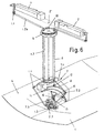
- Outlets (1.3 and 2.3) are mounted on head (7) which is suspended from a column (8) as shown in Figure 6.
- Head (7) comprises three principal parts (7.1, 7.2 and 7.3).
- Part (7.2) of head (7) is mounted on curved guides (11) and is able to perform guided movements along them.
- a pinion (12) driven by a corresponding motor projects from each side of part (7.1) to bring about movement of this part, see Figure 6.
- the two pinions (12) on the two sides are associated with a curved rack (13) on the upper side of part (7.2) so that rotation of pinions (12) is translated into movement of part (7.2) along curved guides (11) in one direction or the other about a theoretical axis identified by the letter Y', as shown in Figure 2.
- gear (16) is coupled to another larger gear (15) in the third part of head (7) identified as part (7.3), as will be seen in Figures 6 and 7.
- outlets (1.3) and (2.3) have three possibilities for different rotational movements about the three axes X', Y', Z', which are related to each other in the same way as the axes of a system of coordinates.
- These possibilities for different combinations of rotational movements together with movements along the X, Y, Z axes with head (7) makes through gantry (3) means that outlets (1.3) and (2.3) can follow trajectories over parts having a flat, curved, conical, or even spherical surface, or combinations of these surfaces, as an attempt has been made to represent diagrammatically in figures 6 to 13.
- the two beams must converge on the focal point established for the purpose at all times.
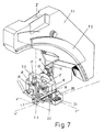
- each of outlets (1.3 and 2.3) is mounted on a support (19) which can move along trajectories which are perpendicular to each other along axes Y" and Z" through the action of two screws (18 and 22) through their corresponding nuts.
- Screw (18) is driven by a motor (17) and screw (22) is driven by a motor (20) through corresponding transmission (21).
- a sensor system (23) of the intelligent type, which detects the difference between actual and theoretical positions virtually in real time, correcting any deviations which occur, in connection with at least one of outlets (1.3 or 2.3).
- the machine includes paired roller tracks (24) in head (7) which contact the sides of sections (5) and a pair of rollers (25) pressing upon them so as to guide movements of head (7) along sections (5).
- rollers (25) are connected to the pistons of corresponding cylinders (26) as will be seen in Figure 15. These cylinders (26) press rollers (25) against the upper edge of sections (5) thus maintaining constant contact between the latter and the former.
- the machine should incorporate additional means and devices in head (7) to improve its working conditions and performance.
- head (7) with a system for the automatic supply of welding rod, together with a chamber for direct visual inspection of the welding and a means for checking weld quality. None of these means and systems are described in detail in this invention because they are conventional means which have already been applied in other welding machines and in any case independent means or systems which themselves bring their own functional characteristics to the machine.
Landscapes
- Physics & Mathematics (AREA)
- Optics & Photonics (AREA)
- Engineering & Computer Science (AREA)
- Plasma & Fusion (AREA)
- Mechanical Engineering (AREA)
- Robotics (AREA)
- Laser Beam Processing (AREA)
Description
- The invention relates to a laser welding machine for the welding of sections in large structural components, especially aluminium spars to curved, cylindrical or spherical aluminium skin sheets in aircraft construction, as defined in the pre-characterizing portion of
claim 1. Such a laser welding machine is known from EP-A-0 838 301. - The question of weight is one of the principal factors which has to be borne in mind in the design of aircraft construction or structures. For this reason aircraft construction makes use of light materials. These must nevertheless have the necessary strength, and this is provided by materials such as aluminium.
- The construction of structures, and especially construction of a fuselage, from aluminium is based on thin aluminium sheets. These sheets form the "skin" of the hull/fuselage. For strength reasons the sheets are reinforced with sections, also made of aluminium, which are known among other things as "spars".
- The spars are attached to the inner side of the structures, providing strength to the skin sheets. Hitherto spars have been riveted to the skin sheet, and because of this the spars have an inverted "T" cross-section through the base of which the rivets pass.
- This process nevertheless gives rise to some problems associated with the point nature of the attachment resulting from the riveting process, the slowness of the riveting process, the considerable weight arising from use of the rivets, and the need to provide the spars with fins at the base to hold the rivets. In the past the attachment of spars by welding has been rejected, as aluminium can only be welded with difficulty, and under special conditions. Also for a long time there were no machines which made it possible to perform automatic high precision welding with the necessary reliability. The welding machine described at the outset is detailed in the progress reports of the VDI (Association of German Engineers)
line 2; Manufacturing Technique no. 326, paper C7.94 by Dip. Ing. Peter Heider, "Laser-appropriate construction and appropriate laser means of manufacture for the welding of large structural components made of aluminium". The known welding jig for the bilateral and simultaneous welding of spars to a skin sheet includes among other things a variable beam/support on which the skin sheet is placed and a flexible tensioning system using roller guides for precise positioning and fixing the spars on the skin sheet during a welding process. - A pair of rollers which precede the laser beam and another positioned behind are provided in relation to the lateral guide for a spar. Each pair of rollers comprises a guide roller for determining the position of the spar and a tensioning roller. The spar is positioned by the mechanised head, which is driven by a digital control program which is orientated through fixed points to the actual position of the skin sheet.
- Pressing of a spar against the skin sheet is ensured by means of two rollers which are placed above the welding zone. Here the prior adjustment of the pressure rollers and the lateral tensioning rollers is adjusted by means of springs, while relative movement between the mechanised head and the workpieces can be applied from both the work pieces and the mechanised head. One disadvantage nevertheless is that known fixing and tensioning equipment is specifically shaped to fit the component.
- US-A-4,223,201 discloses an automated welding facility for the fabrication of shell sections suitable for ship construction and utilizing laser welding.
- The purpose of the invention is to provide a welding machine of the type indicated at the outset which makes automated high precision laser welding, preferably for aluminium sections to aluminium skin sheets in aircraft construction, possible.
- In accordance with the present invention, there is provided laser welding apparatus according to
claim 1. - Further developments of the invention are defined in
dependent claims 2 to 15. - An embodiment of the invention will now be described by way of example with reference to the accompanying drawings in which:-
- Figure 1 is a perspective view which shows the welding machine to which this invention relates in one possible non-restrictive embodiment;
- Figure 2 is a diagrammatical view showing the course of the laser beams from the laser or resonator units (1 and 2) to the outlets (1.3 and 2.3);
- Figure 3 is a side view of the head (7) of the machine;
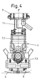
- Figure 4 is a front view of the head (7) in the partial cross-section IV-IV indicated in Figure 3;
- Figure 5 is a view of head (7) from the side opposite that in Figure 3;
- Figure 6 is a perspective diagrammatical view of the machine moving on head (7) over a sheet (4) having a cylindrical surface, over its central generatrix;
- Figure 7 shows a detail of the part of head (7) corresponding to figure 6;
- Figure 8 is a view as that in Figure 6, but in this case with head (7) moving along a generatrix to one side of the central generatrix;
- Figure 9 shows details of part of head (7) corresponding to figure 8;
- Figure 10 is a view similar to that in Figure 6 but now with head (7) moving along the median line of a plate (4) having a conical surface;
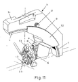
- Figure 11 shows details of the part of head (7) corresponding to figure 10;
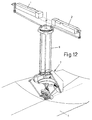
- Figure 12 is a view similar to that in Figure 10 but head (7) is now moving without following the median line of the conical part of the plate (4);
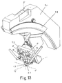
- Figure 13 shows details of the part of head (7) corresponding to figure 12;
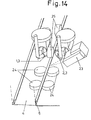
- Figure 14 is a diagrammatical perspective view showing the arrangement of the rollers (24 and 25) supporting head (7) against sections (5);
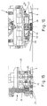
- Figure 15 is a side view of the region of head (7) where the rollers (24 and 25) are located. This view is that along arrow XV shown in Figure 16;
- Figure 16 is a partial cross-section frontal view of the lower part of head (7) housing rollers (24) and sensor (23);
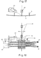
- Figure 17 shows sensor (23) diagrammatically in a view along XVII-XVII in Figure 18; and
- Figure 18 shows the cross-section XVIII-XVIII indicated in Figure 16.
-
- The subject matter of this invention is a laser welding machine, shown diagrammatically and in accordance with a possible embodiment in Figure 1, in which it will be seen that two laser or resonator units (1 and 2) mounted on a frame (6) are located on a portal commonly known as a gantry (3) in such a way that through the movements of gantry (3) frame (6) and with it resonators (1 and 2) can move along the X,Y,Z axes.
- Head (7) of the welding machine hangs from gantry (3) and in the non-restrictive example in Figure 1 is carrying out a welding process in which aluminium sections (5) known commonly as "stringers" are being welded to a curved aluminium sheet (4) belonging to the fuselage of an aircraft so that the two welding beams from the resonators (1 and 2) weld the two sides of stringers (5) in a single pass.
- Figure 2 provides a diagrammatical representation of resonators (1 and 2) and the trajectory followed by each laser beam from resonator (1 or 2) to the corresponding outlet (1.3) or (2.3) respectively.
- As will be seen in Figure 2, tubular conduits (1.2) lead from resonator (1) and of these at least the one indicated by reference (1.2a) is telescopic. The various tubular conduits (1.2 and 1.2a) are connected by means of articulated joints (1.1) within which there is a set of mirrors so that the laser beam leaving resonator (1) is carried through tubular conduits (1.2 and 1.2a) and is redirected by the mirrors at articulated joints (1.1) to reach outlet (1.3). The same thing happens in the case of resonator (2) which is associated with tubular conduits (2.2 and 2.2a) and corresponding articulated nodes (2.1).
- With this arrangement and keeping resonators (1 and 2) static, outlets (1.3) and (2.3) can be moved, and with them the laser beams, as will be seen below.
- Outlets (1.3 and 2.3) are mounted on head (7) which is suspended from a column (8) as shown in Figure 6. Head (7) comprises three principal parts (7.1, 7.2 and 7.3).
- The construction of these three parts (7.1, 7.2 and 7.3) of head (7) is shown in detail in Figures 3, 4 and 5. Thus the part identified by reference (7.1) is the part which is attached to supporting column (8) so that as column (8) rotates about an axis Z', the entire head (7) also rotates about that axis Z'. To bring about rotation of column (8) this comprises a transmission comprising a sprocket (9) and a gearwheel (10) driven by a motor which is not shown, see Figure 6.
- Part (7.2) of head (7) is mounted on curved guides (11) and is able to perform guided movements along them. A pinion (12) driven by a corresponding motor projects from each side of part (7.1) to bring about movement of this part, see Figure 6.
- The two pinions (12) on the two sides are associated with a curved rack (13) on the upper side of part (7.2) so that rotation of pinions (12) is translated into movement of part (7.2) along curved guides (11) in one direction or the other about a theoretical axis identified by the letter Y', as shown in Figure 2.
- In addition to this, a motor (14) which rotates a gear (16) in both directions is mounted on this part (7.2) of head (7). Gear (16) is coupled to another larger gear (15) in the third part of head (7) identified as part (7.3), as will be seen in Figures 6 and 7.
- Through the action of motor (14) part (7.3) of head (7) rotates about a theoretical axis X' as shown in Figure 2.
- In this way outlets (1.3) and (2.3) have three possibilities for different rotational movements about the three axes X', Y', Z', which are related to each other in the same way as the axes of a system of coordinates. These possibilities for different combinations of rotational movements together with movements along the X, Y, Z axes with head (7) makes through gantry (3) means that outlets (1.3) and (2.3) can follow trajectories over parts having a flat, curved, conical, or even spherical surface, or combinations of these surfaces, as an attempt has been made to represent diagrammatically in figures 6 to 13.
- When the laser beams are in use each strikes one side of sections (5) so that section (5) is welded to sheet (4) along both sides through a single pass of head (7). To achieve correct welding the two beams must converge on the focal point established for the purpose at all times.
- In this respect it should be borne in mind that the computer which controls movements of the machine will be programmed in relation to the shapes of sheets (4) and sections (5), but it must be realised that these parts will include some unforeseen irregularities, and that errors, which will be cumulative, may also occur in the trajectories of the beams from resonators (1 and 2) to outlets (1.3 and 2.3). As will be seen below, the machine according to this invention also overcomes these errors and does so virtually in real time.
- In fact, and as will be seen in detail in Figure 7, each of outlets (1.3 and 2.3) is mounted on a support (19) which can move along trajectories which are perpendicular to each other along axes Y" and Z" through the action of two screws (18 and 22) through their corresponding nuts.
- Screw (18) is driven by a motor (17) and screw (22) is driven by a motor (20) through corresponding transmission (21).
- In this way, by moving each of outlets (1.3 and 2.3) along the two perpendicular paths of axes Y" and Z" possible errors can be corrected and focal convergence of the two laser beams can be maintained.
- With this object and for the detection of these errors provision is made for a sensor system (23), of the intelligent type, which detects the difference between actual and theoretical positions virtually in real time, correcting any deviations which occur, in connection with at least one of outlets (1.3 or 2.3).
- Satisfactory tests have been performed with a "scout" sensor system (23) manufactured by Daimler Benz Aerospace, specifically for laser machines.
- It has been provided that if a single sensor (23) is mounted next to one of outlets (1.3 or 2.3) as shown in Figures 14, 16 and 17, this sensor (23) will control motors (17 and 20) corresponding to the two vertical screws (18) of the two outlets (1.3 and 2.3) and the horizontal screw (22) of one of these, the other horizontal screw (22) being moved by digital control. If two sensors (23) are fitted, each will control the motors (17 and 20) of screws (18) and (22) corresponding to outlets (1.3 or 2.3) as appropriate.
- In addition to this, it will be seen, diagrammatically, in Figure 14 that the machine includes paired roller tracks (24) in head (7) which contact the sides of sections (5) and a pair of rollers (25) pressing upon them so as to guide movements of head (7) along sections (5).
- Of the two pairs of rollers (24) those on one side are positioned by corresponding micrometers (27), as will be seen in Figure 18, while those on the other side are pressed against the corresponding side of section (5) through the action of corresponding rollers (28).
- For their part rollers (25) are connected to the pistons of corresponding cylinders (26) as will be seen in Figure 15. These cylinders (26) press rollers (25) against the upper edge of sections (5) thus maintaining constant contact between the latter and the former.
- It has been provided that the machine should incorporate additional means and devices in head (7) to improve its working conditions and performance. Thus provision has been made to provide head (7) with a system for the automatic supply of welding rod, together with a chamber for direct visual inspection of the welding and a means for checking weld quality. None of these means and systems are described in detail in this invention because they are conventional means which have already been applied in other welding machines and in any case independent means or systems which themselves bring their own functional characteristics to the machine.
Claims (15)
- Laser welding apparatus for welding a section to a large structural component, e.g. an aluminium spar to a curved skin sheet in aircraft construction, comprising:characterized in that the outlet opening of each guide member is attached to a head (7) which is mounted for rotation about three axes (X',Y',Z').a support for supporting a structural component;a roller system for guiding a section and pressing it against the structural component;a frame (6) for supporting at least two laser or resonator units (1, 2) through which in use laser beams are simultaneously generated;means for providing relative movement between the frame and the support, andguide members comprising conduits (1.2, 2.2) and articulations (1.1, 2.1) with corresponding internal mirrors, each for directing a laser beam from a respective unit through a respective outlet opening (1.3, 2.3) and towards a respective side of a welding point located close thereto;
- Laser welding machine according to claim 1, wherein there are two laser or resonator units, and the guide members of both units (1, 2) are constructed to be symmetrical to each other.
- Laser welding machine according to claim 1 or claim 2, wherein the ends of the guide members with the outlet openings (1.3, 2.3) are mechanically connected to the head (7) by means of fixing supports (19) which can move along two axes (Y", Z").
- Laser welding machine according to claim 3, wherein the fixing supports (19) have a joint action with threaded screws (18, 22) to bring about movements in the direction of the axes (Y", Z").
- Laser welding machine according to claim 4, wherein the threaded screws (18, 22) are driven by motors (17, 20).
- Laser welding machine according to claim 4 or claim 5, wherein at least one sensor (23) configured to record variations between theoretical and actual movements of the head (7), and passes these to a correction mechanism, is provided for control of the threaded screws (18, 22) and through this for control of the distances between the outlet openings (1.3, 2.3) of the structural members and the welding point.
- Laser welding machine according to any one of the preceding claims, wherein the head (7) comprises:a first component (7.1) fixed to a vertical column (8) which is rotatable about its longitudinal axis (Z');a second component (7.2) movably connected to the first component (7.1) along curved guides (11) located on the first component (7.1), thereby being rotatable about a further axis (Y'); anda third component (7.3), coupled to the second component (7.2) and supporting fixing supports (19) attached to the head (7), which is rotatable about a further axis (X').
- Laser welding machine according to claim 7, wherein the outlet openings (1.3, 2.3) of the guiding members are rotatable independently of each other about three axes (X', Y', Z') or simultaneously about two of those three axes (X',Y',Z').
- Laser welding machine according to any one of the preceding claims, wherein the roller system is mounted on the head (7) and has two pairs of guide rollers (24) which roll along the side walls of the section being welded (5) and pressure rollers (25) which roll along the upper edge of the section (5).
- Laser welding machine according to claim 9, wherein at least one of the two pairs of guide rollers (24) is positioned by means of micrometer screws (27).
- Laser welding machine according to claim 10, wherein the other pair of guide rollers (24) can be pressed against the side wall of the section being welded by means of a pressurising roller (28).
- Laser welding machine according to claim 9, wherein the pressure rollers (25) press against the upper edge of the section being welded (5) through additional pressurising rollers (28).
- Laser welding machine for according to claim 7, wherein the second component (7.2) of the head (7) has a curved rack (13) which acts together with a pinion (12) fixed to the first component (7.1) to bring about gyratory movement of the second component (7.2) with respect to the first component (7.1) about axis of rotation (Y').
- Laser welding machine according to claim 7 and claim 13, characterised in that the second component (7.2) of the head (7) has a motor (14) driving a pinion (16) and in that this pinion (16) acts jointly with a pinion (15) housed in the third component (7.3) to bring about gyratory movement of the third component (7.3) with respect to the second component (7.2) about axis of rotation (X').
- Laser welding apparatus according to any one of the preceding claims, in which the frame (6) is coupled to a gantry (3) for movement along Cartesian axes (X,Y,Z) relative to the support.
Applications Claiming Priority (2)
| Application Number | Priority Date | Filing Date | Title |
|---|---|---|---|
| ES009801884A ES2161113B1 (en) | 1998-09-07 | 1998-09-07 | LASER WELDING MACHINE FOR WELDING PROFILES ON LARGE STRUCTURAL COMPONENTS. |
| ES9801884 | 1998-09-07 |
Publications (2)
| Publication Number | Publication Date |
|---|---|
| EP0985485A1 EP0985485A1 (en) | 2000-03-15 |
| EP0985485B1 true EP0985485B1 (en) | 2003-07-16 |
Family
ID=8305092
Family Applications (1)
| Application Number | Title | Priority Date | Filing Date |
|---|---|---|---|
| EP99306618A Expired - Lifetime EP0985485B1 (en) | 1998-09-07 | 1999-08-20 | Laser welding machine for the welding of sections in large structural components |
Country Status (3)
| Country | Link |
|---|---|
| EP (1) | EP0985485B1 (en) |
| DE (1) | DE69909566T2 (en) |
| ES (1) | ES2161113B1 (en) |
Cited By (1)
| Publication number | Priority date | Publication date | Assignee | Title |
|---|---|---|---|---|
| US8716621B2 (en) | 2009-02-18 | 2014-05-06 | Fabrizio Grassi | Head for the continuous precision machining on three-dimensional bodies and machining equipment that comprises said head |
Families Citing this family (6)
| Publication number | Priority date | Publication date | Assignee | Title |
|---|---|---|---|---|
| CA2558898C (en) * | 2005-09-07 | 2013-11-05 | Purdue Research Foundation | Laser assisted machining process with distributed lasers |
| DE102008052489B4 (en) * | 2008-10-21 | 2012-04-05 | Ibs Filtran Kunststoff-/ Metallerzeugnisse Gmbh | Device for welding two welding articles and method for operating the device |
| DE102010012533A1 (en) * | 2010-03-23 | 2011-09-29 | Fix Maschinenbau Gmbh | Device for laser-welding of cylindrical body, comprises a first sensor by which the position of the cylindrical body is ascertainable and/or first welding head drive by which the welding head is adjusted in an angle to the axial direction |
| DE102010012532A1 (en) * | 2010-03-23 | 2011-09-29 | Fix Maschinenbau Gmbh | Device for laser-welding of cylindrical body, comprises first sensor by which the position of the cylindrical body is ascertainable and/or first welding head drive by which the welding head is adjusted in an angle for the axial direction |
| CN102581482A (en) * | 2012-03-21 | 2012-07-18 | 中国航空工业集团公司北京航空制造工程研究所 | Position adjuster for laser welding head |
| CN109454331B (en) * | 2018-11-30 | 2020-08-04 | 上海航天精密机械研究所 | Double-side laser welding equipment suitable for manufacturing rocket T-shaped structure wall plate |
Family Cites Families (9)
| Publication number | Priority date | Publication date | Assignee | Title |
|---|---|---|---|---|
| US4223201A (en) * | 1978-12-14 | 1980-09-16 | United Technologies Corporation | Laser welding apparatus for shipyard panel shops |
| US4223202A (en) * | 1978-12-14 | 1980-09-16 | United Technologies Corporation | Apparatus and method for welding boat subassemblies utilizing laser radiation |
| US4700045A (en) * | 1985-04-30 | 1987-10-13 | Chesapeake Laser Systems, Inc. | Seam tracking system with acousto-optical scanner |
| DE8713471U1 (en) * | 1987-10-07 | 1987-12-03 | Rofin-Sinar Laser GmbH, 2000 Hamburg | Laser welding machine for welding hollow profiles and flat profiles |
| JPH0352791A (en) * | 1989-07-20 | 1991-03-06 | Fanuc Ltd | Articulated arm type industrial laser robot |
| US5142118A (en) * | 1991-05-14 | 1992-08-25 | Progressive Tool & Industries Co. | Laser welding unit |
| IT1264740B1 (en) * | 1993-11-25 | 1996-10-04 | Irsap Irsol Srl | IMPROVED PROCESS AND SYSTEM FOR THE PRODUCTION OF COLUMN RADIATORS. |
| DE19639667C1 (en) * | 1996-09-27 | 1998-03-12 | Daimler Benz Aerospace Airbus | Process for welding profiles on large-format aluminum structural components using laser beams |
| JPH10124010A (en) * | 1996-10-22 | 1998-05-15 | Hitachi Ltd | Liquid crystal panel and liquid crystal display |
-
1998
- 1998-09-07 ES ES009801884A patent/ES2161113B1/en not_active Expired - Fee Related
-
1999
- 1999-08-20 DE DE69909566T patent/DE69909566T2/en not_active Expired - Lifetime
- 1999-08-20 EP EP99306618A patent/EP0985485B1/en not_active Expired - Lifetime
Cited By (1)
| Publication number | Priority date | Publication date | Assignee | Title |
|---|---|---|---|---|
| US8716621B2 (en) | 2009-02-18 | 2014-05-06 | Fabrizio Grassi | Head for the continuous precision machining on three-dimensional bodies and machining equipment that comprises said head |
Also Published As
| Publication number | Publication date |
|---|---|
| DE69909566T2 (en) | 2004-06-09 |
| ES2161113A1 (en) | 2001-11-16 |
| ES2161113B1 (en) | 2002-08-01 |
| EP0985485A1 (en) | 2000-03-15 |
| DE69909566D1 (en) | 2003-08-21 |
Similar Documents
| Publication | Publication Date | Title |
|---|---|---|
| US5961858A (en) | Laser welding apparatus employing a tilting mechanism | |
| US4781517A (en) | Robotic automobile assembly | |
| CA2225265C (en) | Laser beam welding apparatus | |
| JP6513585B2 (en) | Shape holding jig and aircraft panel manufacturing method | |
| US4223201A (en) | Laser welding apparatus for shipyard panel shops | |
| JPH0436792B2 (en) | ||
| EP1827769B1 (en) | Handling device and method multiaxial handling and guiding workpieces arranged on a supporting device | |
| JPH0596434A (en) | Device for mounting machine tool for supporting and machining workpiece | |
| US20010008231A1 (en) | Apparatus and control system for laser welding | |
| CN108202259B (en) | Machine tool with assembled configuration with cantilevered tool | |
| KR102340728B1 (en) | Retaining device, machining device and method | |
| US20020104833A1 (en) | Welding head mount for robotic welding apparatus with micro adjustment capability | |
| KR102471348B1 (en) | A device for applying rivets to a piece comprising a device for checking and correcting the position of the riveting actuator relative to the piece. | |
| EP1395385B1 (en) | Method and device for the robot-controlled cutting of workpieces to be assembled by means of laser radiation | |
| WO1999037429A1 (en) | Apparatus and method for positioning tooling | |
| CA2215149C (en) | Continuous process and device for butt-welding metal sheets | |
| US5731566A (en) | Device for welding and/or cutting | |
| EP2393626A1 (en) | Apparatus having scanner lens for material processing by way of laser | |
| JPH05208299A (en) | Device for welding structure such as car body comprising thin metal plate that is loosely assembled beforehand and pressed or part thereof | |
| US6101704A (en) | Method for fastening a semi-cylindrical workpiece without refixturing thereof | |
| CN119387841B (en) | Automatic welding device and method for hollow balls | |
| JPH03492A (en) | Laser device | |
| EP0985485A1 (en) | Laser welding machine for the welding of sections in large structural components | |
| US5258598A (en) | Station for assembling pressed sheet-metal structures with welding robots also usable periodically for checking the fixtures used in the station | |
| DE102008029063B4 (en) | Method and device for applying an application structure to a workpiece and for monitoring the application structure |
Legal Events
| Date | Code | Title | Description |
|---|---|---|---|
| PUAI | Public reference made under article 153(3) epc to a published international application that has entered the european phase |
Free format text: ORIGINAL CODE: 0009012 |
|
| AK | Designated contracting states |
Kind code of ref document: A1 Designated state(s): DE FR GB IT |
|
| AX | Request for extension of the european patent |
Free format text: AL;LT;LV;MK;RO;SI |
|
| 17P | Request for examination filed |
Effective date: 20000728 |
|
| RAP1 | Party data changed (applicant data changed or rights of an application transferred) |
Owner name: EADS AIRBUS GMBH Owner name: M. TORRES DISENOS INDUSTRIALES, S.A. |
|
| AKX | Designation fees paid |
Free format text: DE FR GB IT |
|
| RAP1 | Party data changed (applicant data changed or rights of an application transferred) |
Owner name: AIRBUS DEUTSCHLAND GMBH Owner name: M. TORRES DISENOS INDUSTRIALES, S.A. |
|
| 17Q | First examination report despatched |
Effective date: 20020506 |
|
| GRAH | Despatch of communication of intention to grant a patent |
Free format text: ORIGINAL CODE: EPIDOS IGRA |
|
| RIN1 | Information on inventor provided before grant (corrected) |
Inventor name: LUSARRETA, JAVIER MEDINA Inventor name: HERMOSO, JULIAN BAIGORRI Inventor name: NEYE, GERHARD,DAIMLER CHRYSLER AERO. AIRB. GMBH Inventor name: KUCK, GUNTER,DAIMLER CHRYSLER AERO. AIRB. GMBH Inventor name: GEDRAT, OLAF,DAIMLER CHRYSLER AERO. AIRB. GMBH Inventor name: WOLF, MANFRED,DAIMLER CHRYSLER AERO. AIRBUS GMBH Inventor name: MARTINEZ TORRES, MANUEL |
|
| GRAH | Despatch of communication of intention to grant a patent |
Free format text: ORIGINAL CODE: EPIDOS IGRA |
|
| GRAA | (expected) grant |
Free format text: ORIGINAL CODE: 0009210 |
|
| AK | Designated contracting states |
Designated state(s): DE FR GB IT |
|
| REG | Reference to a national code |
Ref country code: GB Ref legal event code: FG4D |
|
| REF | Corresponds to: |
Ref document number: 69909566 Country of ref document: DE Date of ref document: 20030821 Kind code of ref document: P |
|
| ET | Fr: translation filed | ||
| PLBE | No opposition filed within time limit |
Free format text: ORIGINAL CODE: 0009261 |
|
| STAA | Information on the status of an ep patent application or granted ep patent |
Free format text: STATUS: NO OPPOSITION FILED WITHIN TIME LIMIT |
|
| 26N | No opposition filed |
Effective date: 20040419 |
|
| PGFP | Annual fee paid to national office [announced via postgrant information from national office to epo] |
Ref country code: IT Payment date: 20100727 Year of fee payment: 12 |
|
| PGFP | Annual fee paid to national office [announced via postgrant information from national office to epo] |
Ref country code: FR Payment date: 20110812 Year of fee payment: 13 Ref country code: GB Payment date: 20110802 Year of fee payment: 13 |
|
| REG | Reference to a national code |
Ref country code: DE Ref legal event code: R082 Ref document number: 69909566 Country of ref document: DE Representative=s name: RICHTER WERDERMANN GERBAULET HOFMANN, DE |
|
| PG25 | Lapsed in a contracting state [announced via postgrant information from national office to epo] |
Ref country code: IT Free format text: LAPSE BECAUSE OF NON-PAYMENT OF DUE FEES Effective date: 20110820 |
|
| REG | Reference to a national code |
Ref country code: DE Ref legal event code: R082 Ref document number: 69909566 Country of ref document: DE Representative=s name: BIRD & BIRD LLP, DE Effective date: 20120511 Ref country code: DE Ref legal event code: R082 Ref document number: 69909566 Country of ref document: DE Representative=s name: UEXKUELL & STOLBERG, DE Effective date: 20120511 Ref country code: DE Ref legal event code: R081 Ref document number: 69909566 Country of ref document: DE Owner name: AIRBUS OPERATIONS GMBH, DE Free format text: FORMER OWNERS: AIRBUS OPERATIONS GMBH, 21129 HAMBURG, DE; M. TORRES DISENOS INDUSTRIALES, S.A., PAMPLONA, ES Effective date: 20120511 Ref country code: DE Ref legal event code: R081 Ref document number: 69909566 Country of ref document: DE Owner name: AIRBUS OPERATIONS GMBH, DE Free format text: FORMER OWNER: AIRBUS OPERATIONS GMBH, M. TORRES DISENOS INDUSTRIALES,, , ES Effective date: 20120511 |
|
| REG | Reference to a national code |
Ref country code: DE Ref legal event code: R082 Ref document number: 69909566 Country of ref document: DE Representative=s name: BIRD & BIRD LLP, DE Ref country code: DE Ref legal event code: R082 Ref document number: 69909566 Country of ref document: DE Representative=s name: UEXKUELL & STOLBERG, DE |
|
| GBPC | Gb: european patent ceased through non-payment of renewal fee |
Effective date: 20120820 |
|
| REG | Reference to a national code |
Ref country code: FR Ref legal event code: ST Effective date: 20130430 |
|
| PG25 | Lapsed in a contracting state [announced via postgrant information from national office to epo] |
Ref country code: GB Free format text: LAPSE BECAUSE OF NON-PAYMENT OF DUE FEES Effective date: 20120820 |
|
| PG25 | Lapsed in a contracting state [announced via postgrant information from national office to epo] |
Ref country code: FR Free format text: LAPSE BECAUSE OF NON-PAYMENT OF DUE FEES Effective date: 20120831 |
|
| REG | Reference to a national code |
Ref country code: DE Ref legal event code: R082 Ref document number: 69909566 Country of ref document: DE Representative=s name: BIRD & BIRD LLP, DE |
|
| PGFP | Annual fee paid to national office [announced via postgrant information from national office to epo] |
Ref country code: DE Payment date: 20160822 Year of fee payment: 18 |
|
| REG | Reference to a national code |
Ref country code: DE Ref legal event code: R119 Ref document number: 69909566 Country of ref document: DE |
|
| PG25 | Lapsed in a contracting state [announced via postgrant information from national office to epo] |
Ref country code: DE Free format text: LAPSE BECAUSE OF NON-PAYMENT OF DUE FEES Effective date: 20180301 |