EP0985145B1 - Electrophoresis cassette - Google Patents
Electrophoresis cassette Download PDFInfo
- Publication number
- EP0985145B1 EP0985145B1 EP97913691.8A EP97913691A EP0985145B1 EP 0985145 B1 EP0985145 B1 EP 0985145B1 EP 97913691 A EP97913691 A EP 97913691A EP 0985145 B1 EP0985145 B1 EP 0985145B1
- Authority
- EP
- European Patent Office
- Prior art keywords
- bottom plate
- gel
- base portion
- cassette
- opening
- Prior art date
- Legal status (The legal status is an assumption and is not a legal conclusion. Google has not performed a legal analysis and makes no representation as to the accuracy of the status listed.)
- Expired - Lifetime
Links
- 238000001962 electrophoresis Methods 0.000 title claims description 16
- 238000003466 welding Methods 0.000 claims description 12
- 238000000034 method Methods 0.000 claims description 9
- 238000004891 communication Methods 0.000 claims description 3
- 239000000499 gel Substances 0.000 description 60
- 238000005266 casting Methods 0.000 description 9
- 238000007789 sealing Methods 0.000 description 8
- 239000000872 buffer Substances 0.000 description 5
- 238000001502 gel electrophoresis Methods 0.000 description 4
- 125000006850 spacer group Chemical group 0.000 description 4
- 238000004519 manufacturing process Methods 0.000 description 3
- 239000000853 adhesive Substances 0.000 description 2
- 230000001070 adhesive effect Effects 0.000 description 2
- 210000001520 comb Anatomy 0.000 description 2
- 238000000926 separation method Methods 0.000 description 2
- 239000003351 stiffener Substances 0.000 description 2
- HRPVXLWXLXDGHG-UHFFFAOYSA-N Acrylamide Chemical compound NC(=O)C=C HRPVXLWXLXDGHG-UHFFFAOYSA-N 0.000 description 1
- 230000006835 compression Effects 0.000 description 1
- 238000007906 compression Methods 0.000 description 1
- 238000001035 drying Methods 0.000 description 1
- 239000011521 glass Substances 0.000 description 1
- 238000003780 insertion Methods 0.000 description 1
- 230000037431 insertion Effects 0.000 description 1
- 230000001788 irregular Effects 0.000 description 1
- 239000000463 material Substances 0.000 description 1
- 239000002991 molded plastic Substances 0.000 description 1
- 239000004033 plastic Substances 0.000 description 1
- 229920003023 plastic Polymers 0.000 description 1
- 229920002401 polyacrylamide Polymers 0.000 description 1
- 239000002685 polymerization catalyst Substances 0.000 description 1
- 238000006116 polymerization reaction Methods 0.000 description 1
- 238000010186 staining Methods 0.000 description 1
Images


Classifications
-
- G—PHYSICS
- G01—MEASURING; TESTING
- G01N—INVESTIGATING OR ANALYSING MATERIALS BY DETERMINING THEIR CHEMICAL OR PHYSICAL PROPERTIES
- G01N27/00—Investigating or analysing materials by the use of electric, electrochemical, or magnetic means
- G01N27/26—Investigating or analysing materials by the use of electric, electrochemical, or magnetic means by investigating electrochemical variables; by using electrolysis or electrophoresis
- G01N27/416—Systems
- G01N27/447—Systems using electrophoresis
- G01N27/44704—Details; Accessories
Definitions
- the invention relates to a gel electrophoresis cassette. More specifically, the invention relates to a gel electrophoresis cassette that provides maximal gel length while being simple to manufacture, reliable to seal for casting, and easy to use.
- Casting polyacrylamide gels for vertical electrophoresis is commonly done by creating a mold formed of two glass plates separated by thin plastic spacers at the edges (for example US5350552 ).
- the bottom of the mold may be sealed with tape, another spacer, or by compression against a gasket. Once sealed on the edges and bottom, a solution of acrylamide, polymerization catalysts and buffers are introduced into the mold and allowed to polymerize. After the gel has formed, the seal on the bottom is removed to provide an electrical contact for electrophoresis. Automating this casting procedure is a means of reducing cost, user labor, and improving reproducibility.
- Molded plastic cassettes have been described by a number of inventors including Leka, U.S. 5,411,657 (Jule, snap-off bottom); Lebaq, U.S. 5,407,522 (Bioprobe, one piece); Margolis, U.S. 5,288,465 (Gradipore); Kushner, et al., U.S. 4,954,236 (Bio-Rad, hybrid); or have been introduced commercially (Novex, WO98/16820 ).
- Leka The sealing of the mold on three edges is conveniently done in one step by ultrasonic welding, such as exemplified by Leka.
- Leka provides a weakened line along which the bottom seal can be broken away. Breaking off the bottom seal requires substantial force and, in the hands of inexperienced user, often damages the gel in the upper part of the cassette or leaves irregular edges.
- Novex also seals the three edges by ultrasonic welding, but leaves an opening along the bottom edge of one face of the mold. During casting, the opening is sealed with a piece of tape. The tape is convenient to remove for running the gel, but the resultant gel is L-shaped, with a "foot" protruding from one surface of the gel. This is inconvenient for drying or blotting the gel after samples have been electrophoresed.
- Another drawback to the Novex design is that the seal area below the foot reduces the separation length possible compared to a conventional cassette of the same dimensions.
- Kushner, et al describe a two-plate system in which a flat plate is sealed to a molded, cavity-forming plate by use of a waterproof tape. Removing the area of tape between the bottom edge of the flat plate and the lower sealing rib of the molded plate exposes the lower edge of the gel.
- the resultant gel has the same protruding "foot" as seen in the Novex gels.
- Margolis describes a two-piece un-welded design which has no L-shaped foot and is readily opened, but the bottom edge is difficult to seal with a simple application of tape because of the presence of seams where the two halves meet.
- the product as sold seems to be designed not to be sealed at the bottom. Gels can be cast through the open bottom, but it requires an additional casting tank.
- Lebaq describes a one-piece cassette, in which the top is sealed by inserting a comb, thus allowing the gel to be cast upside down.
- a comb as a sealing piece often makes the comb difficult to extract. More objectionable for most users is that the cassette is not readily opened for subsequent treatment of the gel, such as staining or blotting.
- EP555145 discloses an electrophoresis gel cassette comprising a bottom plate.
- a stopper comprising six openings is screwed to the bottom plate, the axes through the six openings define an opening plane.
- a cover plate is spaced apart from the bottom plate in an overlying relationship to define a gel chamber there between.
- the gel chamber defines a gel chamber plane.
- the gel chamber is in communication and alignment with the six openings and the gel chamber plane is generally parallel to the opening plane.
- a gel electrophoresis cassette that does not require a break off bottom seal; does not require an L-shaped, shortened separation length gel; does not have a bottom seam that makes tape sealing difficult; and does not need to be cast upside down with combs and that can be easily opened for subsequent gel treatment.
- a gel electrophoresis cassette that is easy to use, reliable, provides the maximum gel length and is simple to manufacture.
- the present invention addresses the above needs by supplying an electrophoresis gel cassette that includes a bottom plate and a cover plate which define a gel chamber therebetween.
- the gel chamber defines a gel chamber plane.
- the cassette further includes a bottom plate base portion which is connected to the bottom plate.
- the base portion includes an opening therethrough, and the opening defines an opening plane that is generally parallel to the gel chamber plane.
- the bottom plate has an outer face and the bottom plate base portion has an outer face which meets the bottom plate outer face at an included angle of greater that ninety degrees.
- the bottom plate base portion may include a bottom wall connected to the bottom plate, a top wall, and first and second side walls connecting the top and bottom walls. In this embodiment the top, bottom and side walls define the opening through the bottom plate base portion.
- cover plate and bottom plate base portion may include contact faces that contact each other at a seal plane. These contact faces may be sealed, e.g. by sonic welding or adhesives to produce a water-tight seal and to facilitate casting.
- the seal plane may be spaced apart from the bottom plate base portion opening.
- the electrophoresis gel cassette may be fabricated from a cover plate and a bottom plate having an attached bottom plate base portion.
- the cover plate and bottom plate include contact faces and may be as describe above.
- the fabrication process further includes positioning the contact faces proximal to each other and positioning the bottom plate spaced apart from the cover plate, defining a gel chamber therebetween.
- the gel chamber defines a plane that is generally parallel to the bottom plate base portion opening plane.
- the process also includes sealing the contact faces, e.g. by sonically welding or the application of adhesive to the contact faces to produce a water-tight seal.
- the present invention provides an electrophoresis gel cassette one embodiment of which includes a bottom plate and a cover plate.
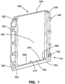
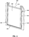
- Figures 1 , 2 , and 3 show one such embodiment: Figure 1 shows a perspective view of one example of a bottom plate; Figure 2 shows a perspective view of one example of a cover plate; and Figure 3 shows a perspective, partially cut-away view of an assembled gel cassette including the bottom and cover plates of Figures 1 and 2 respectively.
- Figure 1 shows a bottom plate 100 according to the present invention that includes a bottom plate base portion 110.
- the bottom plate includes side welding surfaces 120, alignment sockets 130, inner face 140, outer face 150, and edge stiffeners 160.
- the base portion 110 includes a top wall 170, a bottom wall 180, and side walls 190 and 200.
- the bottom plate base portion may also include an optional a support wall 210.
- the bottom plate base portion 110 also includes opening or openings 220 therethrough and an outer face 240. The openings define an opening plane which is shown more clearly in Figures 4 and 5 below.
- the support wall 210 may prevent bowing of the top wall during assembly of the cassette or during electrophoresis.
- Figure 2 shows a cover plate 300 according to the present invention that includes an upper buffer contact notch 310, alignment pins 320, weld director 330, spacer 340, and inner face 350.
- the upper buffer contact notch 310 provides the point of contact between an upper electrophoresis buffer and gel cast in the cassette.
- the upper buffer contact notch 310 is also the point of insertion of combs to form sample wells during casting and polymerization of a gel in the cassette.
- the alignment pins 320 insert into the alignment sockets 130 of the bottom plate when the cassette is assembled.
- the weld director 330 is essentially a thin rib of material extending along the sides and bottom portion of the cover plate 300 which contacts the side welding surfaces 120 and top wall 170 when the cassette is assembled.
- the spacer 340 determines the thickness of the gel by establishing the distance between the inner face of the bottom plate 140 and the inner face of the cover plate 350 when the cassette is assembled.
- the edge stiffener 160 is included on the sides of the bottom plate 100 to prevent bowing of the plates 100 and 300 due to pivoting across the weld when the cassette is clamped by its edges into an electrophoresis unit.
- FIG 3 shows an assembled electrophoresis gel cassette 400 according to the present invention that includes bottom plate 100 and cover plate 300 which define a gel chamber 410 therebetween.
- the gel chamber 410 defines a gel chamber plane which is shown more clearly in Figure 5 below.
- Figures 4 and 5 show cross-sectional views of a portion of the bottom and cover plates shown in Figures 1 and 2 respectively.
- Figure 4 shows the plates prior to assembly and
- Figure 5 shows the assembled gel cassette.
- Figure 4 shows the bottom plate 100 attached to the bottom plate base portion 110 which includes top wall 170, bottom wall 180 and opening 220 through the bottom plate base portion.
- the opening 220 defines an opening plane 250.
- the bottom plate base portion 110 also includes an outer face 240 that meets the bottom plate outer face 150 at an included angle 260.
- Figure 4 shows that the included angle 260 is greater than 90 degrees.
- the bottom plate base portion 110 also includes a contact surface 270 which contacts cover plate contact surface 360 when the cassette is assembled.
- Figure 4 shows an embodiment in which the cover plate contact surface 360 includes the weld director 330 thereon and the bottom plate base portion top wall 170 includes the bottom plate contact surface 270.
- Figure 5 shows bottom plate 100 and cover plate 300 assembled to give the gel cassette 400.
- bottom plate 100 and cover plate 300 define a gel chamber 410 that defines a gel chamber plane 510.
- the gel chamber plane 510 is generally parallel to the opening plane 250 defined by the bottom plate base portion opening 220.
- Figure 5 shows a preferred embodiment in which the planes are parallel which allows for maximum gel length; however, embodiments in which the planes are not exactly parallel are also understood to be within the scope of the invention. Deviations from the planes being substantially parallel will decrease the gel length but so long as the planes are not at 90 degrees the gel length of the invention is longer and therefore superior to the conventional L-shaped gel cassettes.
- Figure 5 also shows one example of a process for assembling the gel cassette 400.
- the process uses a sonic welding to seal the plates 100 and 300.
- the plates 100 and 300 are sonically welded conventionally along the two sides of the plates, i.e. along side welding surfaces 120.
- the weld director is liquefied by heat from the applied sonic energy and forms a water-tight seal between the plates.
- Figure 5 shows a preferred embodiment that includes a sonic welder horn 515 and sonic welder nest 520.
- the weld director 360 is liquefied by heat from sonic energy applied through the sonic welder horn 515 to form a water-tight seal 530 between the bottom plate base portion and cover plate contact surfaces, 270 and 360 respectively.
- Figure 5 shows an embodiment of the invention in which the bottom plate base portion outer face 240 makes an obtuse included angle 260 with the bottom plate outer face 150. Such an embodiment simplifies the welding step.
- the angled face 240 allows the bottom plate base portion 110 to be placed on a sonic welder nest 520 which supports the top wall 170 during the welding process. Because of the angled face 240, no moving nest support arm or sliding of the cassette parts is required to provide a secure support for the top wall 170.
- Figure 5 shows that in the assembled cassette, opening 220 through the base portion 110 allows gel and electric current to flow in a plane 270 generally the same as the plane of the gel chamber 510.
- the opening 220 can be covered with tape during casting, then exposed by removing the tape when the gel is to be used.
- Figure 5 shows an embodiment of the gel cassette in which the outer face of the base portion of the bottom plate 240 has no part lines or seams to interfere with tape sealing, as can also be seen in Figure 3 .
- Figures 1 , 2 and 3 show an embodiment of the invention in which the cover plate 300 includes alignment pin 320 which corresponds to alignment sockets 130 located on the bottom plate 100.
- the pins 320 prevent the cover plate 300 from sliding sideways relative to the bottom plate 100 when pressure is applied to compress the weld director 330 as it is melted by the application of sonic energy through the sonic welder horn 515.
- the pins 320 and sockets 130 combination thus increases the precision of welding, resulting in more reproducible sealing of the cassette and more reproducible uniform gel thickness when casting the gel.
Landscapes
- Health & Medical Sciences (AREA)
- Life Sciences & Earth Sciences (AREA)
- Molecular Biology (AREA)
- Chemical & Material Sciences (AREA)
- General Physics & Mathematics (AREA)
- Immunology (AREA)
- Physics & Mathematics (AREA)
- Analytical Chemistry (AREA)
- Biochemistry (AREA)
- General Health & Medical Sciences (AREA)
- Chemical Kinetics & Catalysis (AREA)
- Electrochemistry (AREA)
- Pathology (AREA)
- Electrostatic Separation (AREA)
- Investigating Or Analysing Biological Materials (AREA)
- Lining Or Joining Of Plastics Or The Like (AREA)
- Electrochromic Elements, Electrophoresis, Or Variable Reflection Or Absorption Elements (AREA)
- Particle Formation And Scattering Control In Inkjet Printers (AREA)
- Eye Examination Apparatus (AREA)
- Apparatus Associated With Microorganisms And Enzymes (AREA)
Description
- The invention relates to a gel electrophoresis cassette. More specifically, the invention relates to a gel electrophoresis cassette that provides maximal gel length while being simple to manufacture, reliable to seal for casting, and easy to use.
- Casting polyacrylamide gels for vertical electrophoresis is commonly done by creating a mold formed of two glass plates separated by thin plastic spacers at the edges (for example
US5350552 ). - The bottom of the mold may be sealed with tape, another spacer, or by compression against a gasket. Once sealed on the edges and bottom, a solution of acrylamide, polymerization catalysts and buffers are introduced into the mold and allowed to polymerize. After the gel has formed, the seal on the bottom is removed to provide an electrical contact for electrophoresis. Automating this casting procedure is a means of reducing cost, user labor, and improving reproducibility.
- Molded plastic cassettes have been described by a number of inventors including Leka,
U.S. 5,411,657 (Jule, snap-off bottom); Lebaq,U.S. 5,407,522 (Bioprobe, one piece); Margolis,U.S. 5,288,465 (Gradipore);Kushner, et al., U.S. 4,954,236 (Bio-Rad, hybrid); or have been introduced commercially (Novex,WO98/16820 - The sealing of the mold on three edges is conveniently done in one step by ultrasonic welding, such as exemplified by Leka. However, to open the bottom, Leka provides a weakened line along which the bottom seal can be broken away. Breaking off the bottom seal requires substantial force and, in the hands of inexperienced user, often damages the gel in the upper part of the cassette or leaves irregular edges.
- Novex also seals the three edges by ultrasonic welding, but leaves an opening along the bottom edge of one face of the mold. During casting, the opening is sealed with a piece of tape. The tape is convenient to remove for running the gel, but the resultant gel is L-shaped, with a "foot" protruding from one surface of the gel. This is inconvenient for drying or blotting the gel after samples have been electrophoresed. Another drawback to the Novex design is that the seal area below the foot reduces the separation length possible compared to a conventional cassette of the same dimensions.
- Kushner, et al, describe a two-plate system in which a flat plate is sealed to a molded, cavity-forming plate by use of a waterproof tape. Removing the area of tape between the bottom edge of the flat plate and the lower sealing rib of the molded plate exposes the lower edge of the gel. The resultant gel has the same protruding "foot" as seen in the Novex gels.
- Margolis describes a two-piece un-welded design which has no L-shaped foot and is readily opened, but the bottom edge is difficult to seal with a simple application of tape because of the presence of seams where the two halves meet. The product as sold seems to be designed not to be sealed at the bottom. Gels can be cast through the open bottom, but it requires an additional casting tank.
- Lebaq describes a one-piece cassette, in which the top is sealed by inserting a comb, thus allowing the gel to be cast upside down. Using a comb as a sealing piece often makes the comb difficult to extract. More objectionable for most users is that the cassette is not readily opened for subsequent treatment of the gel, such as staining or blotting.
-
EP555145 - Thus, there is a need for a gel electrophoresis cassette that does not require a break off bottom seal; does not require an L-shaped, shortened separation length gel; does not have a bottom seam that makes tape sealing difficult; and does not need to be cast upside down with combs and that can be easily opened for subsequent gel treatment. In addition to these requirements, there is a need for a gel electrophoresis cassette that is easy to use, reliable, provides the maximum gel length and is simple to manufacture.
- The present invention addresses the above needs by supplying an electrophoresis gel cassette that includes a bottom plate and a cover plate which define a gel chamber therebetween. The gel chamber defines a gel chamber plane. The cassette further includes a bottom plate base portion which is connected to the bottom plate. The base portion includes an opening therethrough, and the opening defines an opening plane that is generally parallel to the gel chamber plane. According to the invention the bottom plate has an outer face and the bottom plate base portion has an outer face which meets the bottom plate outer face at an included angle of greater that ninety degrees. In another embodiment the bottom plate base portion may include a bottom wall connected to the bottom plate, a top wall, and first and second side walls connecting the top and bottom walls. In this embodiment the top, bottom and side walls define the opening through the bottom plate base portion. In another embodiment the cover plate and bottom plate base portion may include contact faces that contact each other at a seal plane. These contact faces may be sealed, e.g. by sonic welding or adhesives to produce a water-tight seal and to facilitate casting. The seal plane may be spaced apart from the bottom plate base portion opening.
- The electrophoresis gel cassette may be fabricated from a cover plate and a bottom plate having an attached bottom plate base portion. The cover plate and bottom plate include contact faces and may be as describe above. The fabrication process further includes positioning the contact faces proximal to each other and positioning the bottom plate spaced apart from the cover plate, defining a gel chamber therebetween. The gel chamber defines a plane that is generally parallel to the bottom plate base portion opening plane. The process also includes sealing the contact faces, e.g. by sonically welding or the application of adhesive to the contact faces to produce a water-tight seal.
-
-
Figure 1 shows a perspective view of one embodiment of a bottom plate for a gel cassette according to the present invention. -
Figure 2 shows a perspective view of one embodiment of a cover plate for a gel cassette according to the present invention. -
Figure 3 shows a partially cut away perspective view of one embodiment of an assembled gel cassette according to the present invention. -
Figure 4 shows a cross-sectional view of one embodiment of unassembled bottom and cover plates according to the present invention. -
Figure 5 shows a cross-sectional view of one embodiment of an assembled gel cassette according to the present invention. - In these Figures, like numbers designate the same or similar elements.
- The present invention provides an electrophoresis gel cassette one embodiment of which includes a bottom plate and a cover plate.
Figures 1 ,2 , and3 show one such embodiment:Figure 1 shows a perspective view of one example of a bottom plate;Figure 2 shows a perspective view of one example of a cover plate; andFigure 3 shows a perspective, partially cut-away view of an assembled gel cassette including the bottom and cover plates ofFigures 1 and2 respectively. -
Figure 1 shows abottom plate 100 according to the present invention that includes a bottomplate base portion 110. The bottom plate includesside welding surfaces 120,alignment sockets 130,inner face 140,outer face 150, andedge stiffeners 160. Thebase portion 110 includes atop wall 170, abottom wall 180, andside walls support wall 210. The bottomplate base portion 110 also includes opening oropenings 220 therethrough and anouter face 240. The openings define an opening plane which is shown more clearly inFigures 4 and5 below. Thesupport wall 210 may prevent bowing of the top wall during assembly of the cassette or during electrophoresis. -
Figure 2 shows acover plate 300 according to the present invention that includes an upperbuffer contact notch 310, alignment pins 320,weld director 330,spacer 340, andinner face 350. The upperbuffer contact notch 310 provides the point of contact between an upper electrophoresis buffer and gel cast in the cassette. The upperbuffer contact notch 310 is also the point of insertion of combs to form sample wells during casting and polymerization of a gel in the cassette. The alignment pins 320 insert into thealignment sockets 130 of the bottom plate when the cassette is assembled. Theweld director 330 is essentially a thin rib of material extending along the sides and bottom portion of thecover plate 300 which contacts the side welding surfaces 120 andtop wall 170 when the cassette is assembled. Thespacer 340 determines the thickness of the gel by establishing the distance between the inner face of thebottom plate 140 and the inner face of thecover plate 350 when the cassette is assembled. Theedge stiffener 160 is included on the sides of thebottom plate 100 to prevent bowing of theplates -
Figure 3 shows an assembledelectrophoresis gel cassette 400 according to the present invention that includesbottom plate 100 andcover plate 300 which define agel chamber 410 therebetween. Thegel chamber 410 defines a gel chamber plane which is shown more clearly inFigure 5 below. -
Figures 4 and5 show cross-sectional views of a portion of the bottom and cover plates shown inFigures 1 and2 respectively.Figure 4 shows the plates prior to assembly andFigure 5 shows the assembled gel cassette. -
Figure 4 shows thebottom plate 100 attached to the bottomplate base portion 110 which includestop wall 170,bottom wall 180 andopening 220 through the bottom plate base portion. Theopening 220 defines anopening plane 250. The bottomplate base portion 110 also includes anouter face 240 that meets the bottom plateouter face 150 at an includedangle 260.Figure 4 shows that the includedangle 260 is greater than 90 degrees. The bottomplate base portion 110 also includes acontact surface 270 which contacts coverplate contact surface 360 when the cassette is assembled.Figure 4 shows an embodiment in which the coverplate contact surface 360 includes theweld director 330 thereon and the bottom plate base portiontop wall 170 includes the bottomplate contact surface 270. -
Figure 5 showsbottom plate 100 andcover plate 300 assembled to give thegel cassette 400. When assembledbottom plate 100 andcover plate 300 define agel chamber 410 that defines agel chamber plane 510. According to the present invention thegel chamber plane 510 is generally parallel to theopening plane 250 defined by the bottom platebase portion opening 220.Figure 5 shows a preferred embodiment in which the planes are parallel which allows for maximum gel length; however, embodiments in which the planes are not exactly parallel are also understood to be within the scope of the invention. Deviations from the planes being substantially parallel will decrease the gel length but so long as the planes are not at 90 degrees the gel length of the invention is longer and therefore superior to the conventional L-shaped gel cassettes. -
Figure 5 also shows one example of a process for assembling thegel cassette 400. In this embodiment, the process uses a sonic welding to seal theplates plates Figure 5 shows a preferred embodiment that includes asonic welder horn 515 andsonic welder nest 520. During assembly, theweld director 360 is liquefied by heat from sonic energy applied through thesonic welder horn 515 to form a water-tight seal 530 between the bottom plate base portion and cover plate contact surfaces, 270 and 360 respectively.Figure 5 shows an embodiment of the invention in which the bottom plate base portionouter face 240 makes an obtuse includedangle 260 with the bottom plateouter face 150. Such an embodiment simplifies the welding step. Theangled face 240 allows the bottomplate base portion 110 to be placed on asonic welder nest 520 which supports thetop wall 170 during the welding process. Because of theangled face 240, no moving nest support arm or sliding of the cassette parts is required to provide a secure support for thetop wall 170. -
Figure 5 shows that in the assembled cassette, opening 220 through thebase portion 110 allows gel and electric current to flow in aplane 270 generally the same as the plane of thegel chamber 510. Theopening 220 can be covered with tape during casting, then exposed by removing the tape when the gel is to be used.Figure 5 shows an embodiment of the gel cassette in which the outer face of the base portion of thebottom plate 240 has no part lines or seams to interfere with tape sealing, as can also be seen inFigure 3 . -
Figures 1 ,2 and3 show an embodiment of the invention in which thecover plate 300 includesalignment pin 320 which corresponds toalignment sockets 130 located on thebottom plate 100. When seated in thealignment sockets 130, thepins 320 prevent thecover plate 300 from sliding sideways relative to thebottom plate 100 when pressure is applied to compress theweld director 330 as it is melted by the application of sonic energy through thesonic welder horn 515. Thepins 320 andsockets 130 combination thus increases the precision of welding, resulting in more reproducible sealing of the cassette and more reproducible uniform gel thickness when casting the gel.
Claims (5)
- An electrophoresis gel cassette (400), comprising:a bottom plate (100) that includes a bottom plate outer face (150);the bottom plate being attached to a bottom plate base portion (110), wherein the bottom plate base portion includes at least one opening (220) there through that defines an opening plane (250);the bottom plate base portion includes an outer face (240) that meets the bottom plate outer face (150) at an included angle (260);a cover plate (300), wherein the cover plate is spaced apart from the bottom plate in an overlying relationship to define a gel chamber (410) there between; andthe gel chamber being in communication and alignment with the at least one opening, wherein the gel chamber plane (510) defined by the gel chamber (410) is generally parallel to the opening plane (250), the cassette being characterised in that the included angle is obtuse.
- An electrophoresis gel cassette according to claim 1, wherein the bottom plate base portion includes a contact surface and the cover plate includes a contact surface, wherein the contact surface of the bottom plate base portion is configured to contact the contact surface of the cover plate.
- An electrophoresis gel cassette according to the claim 1, wherein the bottom plate and the cover plate are sonically welded to each other to produce a water-tight seal.
- A process for making an electrophoresis gel cassette, comprising:providing a bottom plate that includes a bottom plate outer face;attaching a bottom plate base portion to the bottom plate, wherein the bottom plate base portion includes at least one opening there through that defines an opening plane, wherein the bottom plate base portion includes an outer face that meets the bottom plate outer face at an included angle;providing a cover plate;configuring the cover plate to be spaced apart from the bottom plate in an overlying relationship to define a gel chamber there between; andconfiguring the gel chamber to be in communication and alignment with the at least one opening, wherein the gel chamber plane (510) defined by the gel chamber (410) is generally parallel to the opening plane (250), the process being characterised in that the included angle is obtuse.
- The process for making an electrophoresis gel cassette according to claim 4, further comprising:sonically welding the bottom plate to the cover plate to produce a water-tight seal.
Applications Claiming Priority (5)
| Application Number | Priority Date | Filing Date | Title |
|---|---|---|---|
| US2831496P | 1996-10-11 | 1996-10-11 | |
| US28314P | 1996-10-11 | ||
| US745654 | 1996-11-08 | ||
| US08/745,654 US5827418A (en) | 1996-10-11 | 1996-11-08 | Electrophoresis cassette |
| PCT/US1997/018820 WO1998016820A1 (en) | 1996-10-11 | 1997-10-10 | Electrophoresis cassette |
Publications (3)
| Publication Number | Publication Date |
|---|---|
| EP0985145A1 EP0985145A1 (en) | 2000-03-15 |
| EP0985145A4 EP0985145A4 (en) | 2006-05-24 |
| EP0985145B1 true EP0985145B1 (en) | 2017-04-05 |
Family
ID=26703543
Family Applications (1)
| Application Number | Title | Priority Date | Filing Date |
|---|---|---|---|
| EP97913691.8A Expired - Lifetime EP0985145B1 (en) | 1996-10-11 | 1997-10-10 | Electrophoresis cassette |
Country Status (5)
| Country | Link |
|---|---|
| US (1) | US5827418A (en) |
| EP (1) | EP0985145B1 (en) |
| JP (1) | JP3982838B2 (en) |
| AU (1) | AU738954B2 (en) |
| WO (1) | WO1998016820A1 (en) |
Families Citing this family (35)
| Publication number | Priority date | Publication date | Assignee | Title |
|---|---|---|---|---|
| US6162342A (en) * | 1999-02-12 | 2000-12-19 | Bio-Rad Laboratories, Inc. | Rapid assembly casting system for slab gels |
| US7517442B1 (en) | 1999-08-09 | 2009-04-14 | Life Technologies Corporation | Facile method and apparatus for the analysis of biological macromolecules in two dimensions using common and familiar electrophoresis formats |
| US6379519B1 (en) * | 1999-09-01 | 2002-04-30 | Mirador Dna Design Inc. | Disposable thermoformed electrophoresis cassette |
| US6228508B1 (en) * | 2000-02-07 | 2001-05-08 | Spraying Systems Co. | Process for preparing a metal body having a hermetic seal |
| AU2002210242B2 (en) * | 2000-10-26 | 2004-03-18 | Life Therapeutics Limited | Cassette assembly for electrophoresis gels |
| AUPR103600A0 (en) | 2000-10-26 | 2000-11-16 | Life Therapeutics Limited | Improved electrophoresis gel cassette |
| CA2427022A1 (en) * | 2000-11-02 | 2002-05-10 | Gene Bio-Application Ltd. | Gel trap for electrophoresis |
| WO2002092200A1 (en) * | 2001-05-10 | 2002-11-21 | Invitrogen Corporation | Methods and apparatus for electrophoresis of prior-cast, hydratable separation media |
| US7601251B2 (en) * | 2001-05-10 | 2009-10-13 | Life Technologies Corporation | Methods and apparatus for low resistance electrophoresis of prior-cast, hydratable separation media |
| US6905585B2 (en) * | 2002-09-11 | 2005-06-14 | Temple University Of The Commonwealth System Of Higher Education | Automated system for high-throughput electrophoretic separations |
| US20050011762A1 (en) * | 2003-06-26 | 2005-01-20 | Provonchee Richard B. | Bottom access electrophoresis tray and method of use |
| US7588673B2 (en) * | 2005-09-14 | 2009-09-15 | Bio-Rad Laboratories, Inc. | Electrophoresis cassette with sealing and closure features |
| US8128799B2 (en) * | 2008-05-12 | 2012-03-06 | Bio-Rad Laboratories, Inc. | Welded electrophoresis cassette without leakage-prone weld line |
| US8361299B2 (en) * | 2008-10-08 | 2013-01-29 | Sage Science, Inc. | Multichannel preparative electrophoresis system |
| JP5562342B2 (en) * | 2008-10-08 | 2014-07-30 | セージ サイエンス, インコーポレイテッド | Multi-channel preparative electrophoresis system |
| US8834807B2 (en) | 2009-08-12 | 2014-09-16 | Caliper Life Sciences, Inc. | Device and method for improving sample injection and stacking |
| US8202486B2 (en) * | 2009-08-12 | 2012-06-19 | Caliper Life Sciences, Inc. | Pinching channels for fractionation of fragmented samples |
| US20110042213A1 (en) | 2009-08-24 | 2011-02-24 | Life Technologies Corporation | Gel electrophoresis, imaging, and analysis methods, devices, systems, and materials |
| US20110084194A1 (en) * | 2009-09-24 | 2011-04-14 | Dgel Sciences | Cassette for biological analysis and method of making thereof |
| USD719277S1 (en) | 2010-08-24 | 2014-12-09 | Life Technologies Corporation | Electrophoresis wedge-well comb |
| CN104364640B (en) * | 2012-05-31 | 2016-10-26 | 通用电气健康护理生物科学股份公司 | The method manufacturing electrophoresis cartridge |
| EP2856132A4 (en) | 2012-05-31 | 2016-05-18 | Ge Healthcare Bio Sciences Ab | ELECTROPHORESIS GEL CASSETTE AND METHOD FOR FILLING AN ELECTROPHORESIS GEL CASSETTE |
| AU2013329110B2 (en) | 2012-10-12 | 2017-05-04 | Sage Science, Inc. | Side-eluting molecular fractionator |
| USD733918S1 (en) * | 2013-11-21 | 2015-07-07 | Ge Healthcare Bio-Sciences Ab | Electrophoresis cassette |
| USD733919S1 (en) * | 2013-11-21 | 2015-07-07 | Ge Healthcare Bio-Sciences Ab | Electrophoresis cassette |
| US10131901B2 (en) | 2014-10-15 | 2018-11-20 | Sage Science, Inc. | Apparatuses, methods and systems for automated processing of nucleic acids and electrophoretic sample preparation |
| USD856528S1 (en) | 2015-11-13 | 2019-08-13 | Life Technologies Corporation | Cassette clamp for electrophoresis gel casting |
| USD792603S1 (en) | 2015-11-13 | 2017-07-18 | Life Technologies Corporation | Rig for electrophoresis gel casting |
| WO2017083609A1 (en) | 2015-11-13 | 2017-05-18 | Life Technologies Corporation | Preparation of electrophoresis gels, and related devices, systems, and methods |
| USD859688S1 (en) | 2015-11-13 | 2019-09-10 | Life Technologies Corporation | Electrophoresis slab gel sample loading guide |
| USD851779S1 (en) | 2015-11-13 | 2019-06-18 | Life Technologies Corporation | Electrophoresis cassette with sample loading guide |
| USD849963S1 (en) | 2015-11-13 | 2019-05-28 | Life Technologies Corporation | Electrophoresis gel cassette |
| USD816865S1 (en) | 2015-11-13 | 2018-05-01 | Life Technologies Corporation | Cassette support base for electrophoresis gel casting |
| AU2016357319B2 (en) | 2015-11-20 | 2022-03-10 | Sage Science, Inc. | Preparative electrophoretic method for targeted purification of genomic DNA fragments |
| WO2018187779A1 (en) | 2017-04-07 | 2018-10-11 | Sage Science, Inc. | Systems and methods for detection of genetic structural variation using integrated electrophoretic dna purification |
Family Cites Families (9)
| Publication number | Priority date | Publication date | Assignee | Title |
|---|---|---|---|---|
| US4035377A (en) * | 1975-06-23 | 1977-07-12 | Cold Spring Harbor Laboratory | Slab gel electrophoresis apparatus |
| US4954236A (en) * | 1989-06-28 | 1990-09-04 | Bio-Rad Laboratories, Inc. | Apparatus and method for gel casting and electrophoresis in a single enclosure |
| FR2677894B1 (en) * | 1991-06-20 | 1993-10-15 | Bioprobe Systems | ELECTROPHORESIS DEVICE. |
| US5340461A (en) * | 1992-02-03 | 1994-08-23 | Nakano Vinegar Co., Ltd. | Electrophoretic medium for electrophoretic separation, gel holder for holding the same medium, slab type electrophoretic apparatus using the same medium and gel holder, and electrophoretic gel cutter |
| JP3071927B2 (en) * | 1992-02-07 | 2000-07-31 | 第一化学薬品株式会社 | Method for producing gel plate for electrophoresis |
| US5288465A (en) * | 1992-09-22 | 1994-02-22 | Gradipore Limited | Cassetes for electrophoretic gels |
| US5411657A (en) * | 1993-09-14 | 1995-05-02 | Leka; George T. | Molded plastic electrophoresis cassettes |
| AU3512695A (en) * | 1994-09-19 | 1996-04-09 | Novel Experimental Technology | Plastic mold for electrophoresis gel |
| US5543023A (en) * | 1995-10-04 | 1996-08-06 | Biotech Holdings, Inc. | Gel electrophoresis cassette |
-
1996
- 1996-11-08 US US08/745,654 patent/US5827418A/en not_active Expired - Lifetime
-
1997
- 1997-10-10 JP JP51862498A patent/JP3982838B2/en not_active Expired - Lifetime
- 1997-10-10 WO PCT/US1997/018820 patent/WO1998016820A1/en not_active Ceased
- 1997-10-10 AU AU50819/98A patent/AU738954B2/en not_active Ceased
- 1997-10-10 EP EP97913691.8A patent/EP0985145B1/en not_active Expired - Lifetime
Also Published As
| Publication number | Publication date |
|---|---|
| US5827418A (en) | 1998-10-27 |
| JP3982838B2 (en) | 2007-09-26 |
| AU5081998A (en) | 1998-05-11 |
| AU738954B2 (en) | 2001-10-04 |
| EP0985145A1 (en) | 2000-03-15 |
| WO1998016820A1 (en) | 1998-04-23 |
| EP0985145A4 (en) | 2006-05-24 |
| JP2001503142A (en) | 2001-03-06 |
Similar Documents
| Publication | Publication Date | Title |
|---|---|---|
| US5827418A (en) | Electrophoresis cassette | |
| US4576693A (en) | Nucleic acid sequencing electrophoresis apparatus and method of fabricating | |
| US5433837A (en) | Gel cassette for enhanced electrophoretic separation and processes for the preparation thereof | |
| JP3029248B2 (en) | Electrophoresis cell for quick assembly slab gel | |
| US5411657A (en) | Molded plastic electrophoresis cassettes | |
| JP2620504B2 (en) | Sample well insert for forming wedge-shaped wells in ultra-thin slab gel for electrophoresis | |
| EP0676822A1 (en) | Injection molded battery containment for bipolar batteries | |
| WO1998016820B1 (en) | Electrophoresis cassette | |
| EP0809801B1 (en) | Gel cassette and method of using same | |
| US5543023A (en) | Gel electrophoresis cassette | |
| EP0823321B1 (en) | Joining thermoplastic cases and covers by fusion | |
| JPH0795061B2 (en) | Molecular transfer device by reduced pressure and molecular transfer device by electrophoresis and reduced pressure | |
| US6093301A (en) | Slab gel cassettes with side openings | |
| US20030127331A1 (en) | Two-dimensional electrophoresis method and cassette | |
| US5232573A (en) | Integral electrophoresis gel form | |
| US5429697A (en) | Method of sealing a module | |
| US3988230A (en) | Chamber and process for crossed immunoelectro-phoresis | |
| EP2277034B1 (en) | Welded electrophoresis cassette without leakage-prone weld line | |
| JPS61165954A (en) | Explosion-proof type vent plug for storage battery | |
| JPH0195527A (en) | Wire bonding equipment | |
| CN218834456U (en) | Gel preparation facilities for electrophoresis | |
| RU2214654C2 (en) | Storage battery sealing method | |
| JPH05325921A (en) | Sealed lead-acid battery | |
| JPH01243370A (en) | Cell pack | |
| JPS6275248A (en) | two-dimensional electrophoresis device |
Legal Events
| Date | Code | Title | Description |
|---|---|---|---|
| PUAI | Public reference made under article 153(3) epc to a published international application that has entered the european phase |
Free format text: ORIGINAL CODE: 0009012 |
|
| 17P | Request for examination filed |
Effective date: 19990518 |
|
| AK | Designated contracting states |
Kind code of ref document: A1 Designated state(s): CH DE FR GB IT LI NL SE |
|
| RAP1 | Party data changed (applicant data changed or rights of an application transferred) |
Owner name: AMERSHAM BIOSCIENCES (SF) CORP. |
|
| A4 | Supplementary search report drawn up and despatched |
Effective date: 20060411 |
|
| RIC1 | Information provided on ipc code assigned before grant |
Ipc: G01N 27/447 20060101AFI20060405BHEP |
|
| 17Q | First examination report despatched |
Effective date: 20061103 |
|
| RAP1 | Party data changed (applicant data changed or rights of an application transferred) |
Owner name: GE HEALTHCARE BIO-SCIENCES CORP. |
|
| GRAP | Despatch of communication of intention to grant a patent |
Free format text: ORIGINAL CODE: EPIDOSNIGR1 |
|
| INTG | Intention to grant announced |
Effective date: 20161026 |
|
| GRAS | Grant fee paid |
Free format text: ORIGINAL CODE: EPIDOSNIGR3 |
|
| GRAA | (expected) grant |
Free format text: ORIGINAL CODE: 0009210 |
|
| AK | Designated contracting states |
Kind code of ref document: B1 Designated state(s): CH DE FR GB IT LI NL SE |
|
| REG | Reference to a national code |
Ref country code: GB Ref legal event code: FG4D |
|
| REG | Reference to a national code |
Ref country code: CH Ref legal event code: EP |
|
| REG | Reference to a national code |
Ref country code: DE Ref legal event code: R096 Ref document number: 69740891 Country of ref document: DE |
|
| REG | Reference to a national code |
Ref country code: NL Ref legal event code: MP Effective date: 20170405 |
|
| PG25 | Lapsed in a contracting state [announced via postgrant information from national office to epo] |
Ref country code: NL Free format text: LAPSE BECAUSE OF FAILURE TO SUBMIT A TRANSLATION OF THE DESCRIPTION OR TO PAY THE FEE WITHIN THE PRESCRIBED TIME-LIMIT Effective date: 20170405 |
|
| REG | Reference to a national code |
Ref country code: DE Ref legal event code: R071 Ref document number: 69740891 Country of ref document: DE |
|
| REG | Reference to a national code |
Ref country code: CH Ref legal event code: PL |
|
| PG25 | Lapsed in a contracting state [announced via postgrant information from national office to epo] |
Ref country code: SE Free format text: LAPSE BECAUSE OF FAILURE TO SUBMIT A TRANSLATION OF THE DESCRIPTION OR TO PAY THE FEE WITHIN THE PRESCRIBED TIME-LIMIT Effective date: 20170405 |
|
| REG | Reference to a national code |
Ref country code: DE Ref legal event code: R097 Ref document number: 69740891 Country of ref document: DE |
|
| PLBE | No opposition filed within time limit |
Free format text: ORIGINAL CODE: 0009261 |
|
| STAA | Information on the status of an ep patent application or granted ep patent |
Free format text: STATUS: NO OPPOSITION FILED WITHIN TIME LIMIT |
|
| REG | Reference to a national code |
Ref country code: GB Ref legal event code: PE20 Expiry date: 20171009 |
|
| 26N | No opposition filed |
Effective date: 20180108 |
|
| PG25 | Lapsed in a contracting state [announced via postgrant information from national office to epo] |
Ref country code: GB Free format text: LAPSE BECAUSE OF EXPIRATION OF PROTECTION Effective date: 20171009 |