EP0984662A2 - Waveguide electroacoustical transducing - Google Patents
Waveguide electroacoustical transducing Download PDFInfo
- Publication number
- EP0984662A2 EP0984662A2 EP99306839A EP99306839A EP0984662A2 EP 0984662 A2 EP0984662 A2 EP 0984662A2 EP 99306839 A EP99306839 A EP 99306839A EP 99306839 A EP99306839 A EP 99306839A EP 0984662 A2 EP0984662 A2 EP 0984662A2
- Authority
- EP
- European Patent Office
- Prior art keywords
- waveguide
- cross
- sectional area
- accordance
- section
- Prior art date
- Legal status (The legal status is an assumption and is not a legal conclusion. Google has not performed a legal analysis and makes no representation as to the accuracy of the status listed.)
- Granted
Links
- 230000002463 transducing effect Effects 0.000 title 1
- 230000013011 mating Effects 0.000 claims description 6
- 239000011358 absorbing material Substances 0.000 description 9
- 230000005855 radiation Effects 0.000 description 5
- 230000015572 biosynthetic process Effects 0.000 description 3
- 102220047090 rs6152 Human genes 0.000 description 3
- 239000002537 cosmetic Substances 0.000 description 2
- 238000013016 damping Methods 0.000 description 2
- 230000000694 effects Effects 0.000 description 2
- 230000000712 assembly Effects 0.000 description 1
- 238000000429 assembly Methods 0.000 description 1
- 239000000919 ceramic Substances 0.000 description 1
- 238000005094 computer simulation Methods 0.000 description 1
- 230000001788 irregular Effects 0.000 description 1
Images


Classifications
-
- H—ELECTRICITY
- H04—ELECTRIC COMMUNICATION TECHNIQUE
- H04R—LOUDSPEAKERS, MICROPHONES, GRAMOPHONE PICK-UPS OR LIKE ACOUSTIC ELECTROMECHANICAL TRANSDUCERS; DEAF-AID SETS; PUBLIC ADDRESS SYSTEMS
- H04R1/00—Details of transducers, loudspeakers or microphones
- H04R1/20—Arrangements for obtaining desired frequency or directional characteristics
- H04R1/22—Arrangements for obtaining desired frequency or directional characteristics for obtaining desired frequency characteristic only
- H04R1/28—Transducer mountings or enclosures modified by provision of mechanical or acoustic impedances, e.g. resonator, damping means
- H04R1/2807—Enclosures comprising vibrating or resonating arrangements
- H04R1/2853—Enclosures comprising vibrating or resonating arrangements using an acoustic labyrinth or a transmission line
- H04R1/2857—Enclosures comprising vibrating or resonating arrangements using an acoustic labyrinth or a transmission line for loudspeaker transducers
-
- H—ELECTRICITY
- H04—ELECTRIC COMMUNICATION TECHNIQUE
- H04R—LOUDSPEAKERS, MICROPHONES, GRAMOPHONE PICK-UPS OR LIKE ACOUSTIC ELECTROMECHANICAL TRANSDUCERS; DEAF-AID SETS; PUBLIC ADDRESS SYSTEMS
- H04R1/00—Details of transducers, loudspeakers or microphones
- H04R1/20—Arrangements for obtaining desired frequency or directional characteristics
- H04R1/32—Arrangements for obtaining desired frequency or directional characteristics for obtaining desired directional characteristic only
- H04R1/34—Arrangements for obtaining desired frequency or directional characteristics for obtaining desired directional characteristic only by using a single transducer with sound reflecting, diffracting, directing or guiding means
- H04R1/345—Arrangements for obtaining desired frequency or directional characteristics for obtaining desired directional characteristic only by using a single transducer with sound reflecting, diffracting, directing or guiding means for loudspeakers
Landscapes
- Health & Medical Sciences (AREA)
- Otolaryngology (AREA)
- Physics & Mathematics (AREA)
- Engineering & Computer Science (AREA)
- Acoustics & Sound (AREA)
- Signal Processing (AREA)
- Obtaining Desirable Characteristics In Audible-Bandwidth Transducers (AREA)
- Waveguide Aerials (AREA)
Abstract
length approximately equal to
length of said waveguide and n is a positive integer. The product of a first set of alternating segments is greater than the product of a second set of alternating segments, in one embodiment, by a factor of three. In a third aspect of the invention, the first two aspects are combined.
Description
- The invention relates to acoustic waveguide loudspeaker systems, and more particularly to those with waveguides which have nonuniform cross-sectional areas. For background, reference is made to U.S. Pat. 4,628,528 and to U.S. Patent application 08/058478, entitled "Frequency Selective Acoustic Waveguide Damping" filed May 5, 1993, incorporated herein by reference.
- It is an important object of the invention to provide an improved waveguide.
- According to the invention, a waveguide loudspeaker system for radiating sound waves includes a low loss waveguide for transmitting sound waves. The waveguide includes a first terminus coupled to a loudspeaker driver, a second terminus adapted to radiate the sound waves to the external environment, a centerline running the length of the waveguide, and walls enclosing cross-sectional areas in planes perpendicular to the centerline. The walls are tapered such that the cross-sectional area of the second terminus is less than the cross-sectional area of the first terminus.
- In another aspect of the invention, a waveguide loudspeaker system for radiating sound waves includes a low loss waveguide for transmitting sound waves. The waveguide includes a first terminus coupled to a loudspeaker driver, a second terminus adapted to radiate the sound waves to the external environment, a centerline, walls enclosing cross-sectional areas in planes perpendicular to the centerline, and a plurality of sections along the length of the centerline. Each of the sections has a first end and a second end, the first end nearer the first terminus than the second terminus and the second end nearer the second terminus than the first terminus, each of the sections having an average cross-sectional area. A first of the plurality of sections and a second of the plurality of sections are constructed and arranged such that there is a mating of the second end of the first section to the first end of the second section. The cross-sectional area of the second end of the first section has a substantially different cross-sectional area than the first end of the second section.
- In still another aspect of the invention, a waveguide loudspeaker system for radiating sound waves includes a low loss waveguide for transmitting sound waves. The waveguide includes a first terminus coupled to a loudspeaker driver, a second terminus adapted to radiate the sound waves to the external environment, a centerline, running the length of the waveguide, walls enclosing cross-sectional areas in planes perpendicular to the centerline, and a plurality of sections along the length of the centerline. Each of the sections has a first end and a second end, the first end nearer the first terminus and the second end nearer the second terminus. A first of the plurality of sections and a second of the plurality of sections are constructed and arranged such that there is a mating of the second end of the first section to the first end of the second section. The cross-sectional area of the first section increases from the first end to the second end according to a first exponential function and the cross-sectional area of the second end of the first section is larger than the cross-sectional area of the first end of the second section.
- In still another aspect of the invention, a waveguide loudspeaker system for radiating sound waves includes a low loss waveguide for transmitting sound waves. The waveguide has a tuning frequency which has a corresponding tuning wavelength. The waveguide includes a centerline, running the length of the waveguide, walls enclosing cross-sectional areas in planes perpendicular to the centerline, and a plurality of sections along the centerline. Each of the sections has a length of approximately one fourth of the tuning wavelength, and each of the sections has an average cross-sectional area. The average cross-sectional area of a first of the plurality of sections is different than the average cross-sectional area of an adjacent one of the plurality of sections.
- In still another aspect of the invention, a waveguide for radiating sound waves has segments of length approximately equal towhere l effective length of the waveguide and n is a positive integer. Each of the segments has an average cross-sectional area. A product of the average cross-sectional areas of a first set of alternating segments is greater than two times a product of the average cross-sectional areas of a second set of alternating segments.

- Other features, objects, and advantages will become apparent from the following detailed description, which refers to the following drawings in which:
- FIG. 1 is a cross-sectional view of a waveguide loudspeaker system according to the invention;
- FIGs. 2a and 2b are computer simulated curves of acoustic power and driver excursions, respectively vs. frequency for a waveguide according to the invention and for a conventional waveguide;
- FIG.3 is a cross-sectional view of a prior art waveguide;
- FIG. 4 is a cross-sectional view of a waveguide according to a second aspect of the invention;
- FIGS. 5a and 6a are cross-sectional views of variations of the waveguide of FIG. 4;
- FIG. 7a is a cross-sectional view of a superposition of the waveguide of FIG. 5b on the waveguide of FIG. 5a;
- FIGS. 5b, 5c, 6b, 6c, and 7b are computer simulated curves of acoustic power vs. frequency for the waveguides of FIG. 5a, 6a, and 7a, respectively;
- FIG. 8 is a computer simulated curve of acoustic power vs. frequency for a waveguide according to FIG.4, with sixteen sections;
- FIG. 9 is a computer simulated curve of acoustic power vs. frequency for a waveguide resulting from the superposition on the waveguide of FIG. 7a of a waveguide according to FIG. 4, with sixteen sections;
- FIG. 10 is a cross section of a waveguide resulting from the superposition on the waveguide of FIG. 7a of a large number of waveguides according to FIG. 4, with a large number of sections;
- FIG. 11 is a cross section of a waveguide with standing waves helpful in explaining the length of the sections of waveguides of previous figures;
- FIGS. 12a, 12b, and 12c, are cross sections of waveguides illustrating other embodiments of the invention;
- FIG. 13 is a cross section of a waveguide combining the embodiments of FIGS. 1 and 4;
- FIGS. 14a - 14c are cross sections of similar to the embodiments of FIGS. 5a, 6a, and 7a, combined with the embodiment of FIG. 1; and
- FIGS. 15a and 15b are cross sections of waveguides combining the embodiment of FIG. 10 with the embodiment of FIG. 1.
-
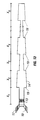
- With reference now to the drawings and more particularly to FIG. 1 there is shown a loudspeaker and waveguide assembly according to the invention. A
waveguide 14 has a first end orterminus 12 and a second end orterminus 16. Waveguide 14 is in the form of a hollow tube of narrowing cross sectional area. Walls ofwaveguide 14 are tapered, such that the cross-sectional area of the waveguide atfirst end 12 is larger than the cross-sectional area at thesecond end 16.Second end 16 may be slightly flared for acoustic or cosmetic reasons. The cross section (as taken along line A-A of FIG. 1, perpendicular to thecenterline 11 of waveguide 14) may be circular, oval, or a regular or irregular polyhedron, or some other closed contour. Waveguide 14 may be closed ended or open ended. Both ends may radiate into free air as shown or one end may radiate into an acoustic enclosure, such as a closed or ported volume or a tapered or untapered waveguide. - For clarity of explanation, the walls of
waveguide 14 are shown as straight andwaveguide 14 is shown as uniformly tapered along its entire length. In a practical implementation, the waveguide may be curved to be a desired shape, to fit into an enclosure, or to position one end of the waveguide relative to the other end of the waveguide for acoustical reasons. The cross section ofwaveguide 14 may be of different geometry, that is, have a different shape or have straight or curved sides, at different points along its length. Additionally, the taper of the waveguide vary along the length of the waveguide. - An
electroacoustical transducer 10 is positioned infirst end 12 of thewaveguide 14. In one embodiment of the invention,electroacoustical transducer 10 is a cone type 65 mm driver with a ceramic magnet motor, but may be another type of cone and magnet transducer or some other sort of electroacoustical transducer. Either side ofelectroacoustical transducer 10 may be mounted infirst end 12 ofwaveguide 14, or theelectroacoustical transducer 10 may be mounted in a wall ofwaveguide 14 adjacentfirst end 12 and radiate sound waves intowaveguide 14. Additionally, the surface of theelectroacoustical transducer 10 that faces away fromwaveguide 14 may radiate directly to the surrounding environment as shown, or may radiate into an acoustical element such as a tapered or untapered waveguide, or a closed or ported enclosure. - Interior walls of
waveguide 14 are essentially lossless acoustically. In the waveguide may be a small amount of acoustically absorbingmaterial 13. The small amount of acoustically absorbingmaterial 13 may be placed near thetransducer 10, as described in co-pending U.S. Patent Application 08/058478, entitled "Frequency Selective Acoustic Waveguide Damping" so that the waveguide is low loss at low frequencies with a relatively smooth response at high frequencies. The small amount of acoustically absorbing material damps undesirable resonances and provides a smoother output over the range of frequencies radiated by the waveguide but does not prevent the formation of low frequency standing waves in the waveguide. - In one embodiment of the invention, the waveguide is a conically tapered waveguide in which the cross-sectional area at points along the waveguide is described by the formulawhere A represents the area, where y = the distance measured from the inlet (wide) end, where

- In one embodiment the length x of
waveguide 14 is 26 inches. The cross-sectional area atfirst end 12 is 6.4 square inches and the cross-sectional area at thesecond end 16 is 0.9 square inches so that the area ratio (defined as the cross-sectional area of thefirst end 12 divided by the cross-sectional area of the second end 16) is about 7.1. - Referring now to FIGs. 2a and 2b, there are shown computer simulated curves of radiated acoustic power and driver excursion vs. frequency for a waveguide loudspeaker system according to the invention (curve 32), without acoustically absorbing
material 13 and with a length of 26 inches, and for a straight walled undamped waveguide of similar volume and of a length of 36 inches (curve 34). As can be seen from FIGs. 2a and 2b, the bass range extends to approximately the same frequency (about 70 Hz) and the frequency response for the waveguide system according to the invention is flatter than the untapered waveguide system. Narrowband peaks (hereinafter "spikes") in the two curves can be significantly reduced by the use of acoustically absorbing material (13 of FIG. 1). - Referring now to FIG. 3, there is shown a prior art loudspeaker and waveguide assembly for the purpose of illustrating a second aspect of the invention. An electroacoustical transducer lO' is positioned in one
end 40 of an open ended uniform cross-sectional waveguide 14' which has a length y. The ends of the waveguide are in close proximity to each other (i.e. distance t is small). When transducer 10' radiates a sound wave of a frequency f with wavelength ∼ which is equal to y, the radiation from the waveguide is of inverse phase to the direct radiation from the transducer, and therefore the radiation from the assembly is significantly reduced at that frequency. - Referring now to FIG. 4, there is shown a loudspeaker and waveguide assembly illustrating an aspect of the invention which significantly reduces the waveguide end positioning problem shown in FIG. 3 and described in the accompanying text. An
electroacoustical transducer 10 is positioned in an end orterminus 12 of an open-endedwaveguide 14a.Electroacoustical transducer 10 may be a cone and magnet transducer as shown, or some other sort of electroacoustical transducer, such as electrostatic, piezoelectric or other source of sound pressure waves.Electroacoustical transducer 10 may face either end ofwaveguide 14a, or may be mounted in a wall ofwaveguide 14a and radiate sound waves intowaveguide 14a.Cavity 17 in whichelectroacoustical transducer 10 is positioned closely conforms to electroacousticaltransducer 10. In this embodiment, interior walls ofwaveguide 14a are acoustically low loss. Inwaveguide 14a may be a small amount of acoustically absorbingmaterial 13, so that the waveguide is low loss acoustically at low frequencies and has a relatively flat response at higher frequencies. The small amount of acoustically absorbing material damps undesirable resonances and provides a smoother output over the range of frequencies radiated by the waveguide but does not prevent the formation of standing waves in the waveguide. Second end, orterminus 16, ofwaveguide 14a radiates sound waves to the surrounding environment.Second end 16 may be flared outwardly for cosmetic or acoustic purposes. -
Waveguide 14a has a plurality ofsections sections - Referring now to FIG. 5a, there is shown a loudspeaker and waveguide assembly according to FIG. 4, with n = 4. When the transducer of FIG. 5a radiates sound of a frequency f with a corresponding wavelength λ which is equal to x, the radiation from the waveguide is of inverse phase to the radiation from the transducer, but the volume velocity, and hence the amplitude, is significantly different. Therefore, even if
waveguide 14a is configured such that the ends are in close proximity, as in FIG. 3, the amount of cancellation is significantly reduced. - In one embodiment of an assembly according to FIG. 5a, the cross section of the waveguide is round, with dimensions A1 and A3 being 0.53 square inches and A2 and A4 being 0.91 square inches.
- In other embodiments of the invention, the product of A2 and A4 is three times the product of A1 and A3, that is
A and A2 = A4 = 1.268A , whereA is the average cross-sectional area of the waveguide, satisfies the relationship. - Referring now to FIG. 5b, there are shown two computer simulated curves of output acoustic power vs. frequency for a waveguide system with the ends of the waveguide spaced S cm apart.
Curve 42, representing the conventional waveguide as shown in FIG. 3, shows asignificant output dip 46 at approximately 350 Hz (hereinafter the cancellation frequency of the waveguide, corresponding to the frequency at which the wavelength is equal to the effective length of the waveguide), and similar dips at integer multiples of the cancellation frequency. Dashedcurve 44, representing the waveguide system of FIG. Sa, shows that the output dips at about 350 Hz and at the odd multiples of the cancellation frequency have been largely eliminated. - Referring now to FIG. 6a, there is shown a loudspeaker and waveguide assembly according to FIG. 4, with n = 8. Each section is of length x/8, where x is the total length of the waveguide. In this embodiment, cross-sectional areas A1...A8 satisfy the relationship
A , whereA is the average cross-sectional area of the waveguide, satisfies the relationship - Referring now to FIG. 6b, there are shown two computer simulated curves of output acoustic power vs. frequency for a waveguide with the ends of the waveguide spaced S cm apart.
Curve 52, representing a conventional waveguide as shown in FIG. 3, shows asignificant output dip 56 at approximately 350-Hz, and similar dips at integral multiples of about 350 Hz. Dashedcurve 54, representing the waveguide of FIG. 6a, shows that the output dips at two times the cancellation frequency and at two times the odd multiples of the cancellation frequency (i.e. 2times - Superimposing the waveguide of FIG. 6a on the waveguide of FIG. 5a yields the waveguide of FIG. 7a. In one embodiment of the assembly of FIG. 5c, A1 = A5 = 0.63
A , A2 = A6 = 0.83A, A3 = A7 = 1.09A and A4 = A8 = 1.44A , and the length of each section is x/8. - Referring now to FIG. 7b, there are shown two computer-simulated curves of output acoustic power vs. frequency for a waveguide with the ends of the waveguide spaced 5 cm apart. Dashed
curve 60, representing the conventional waveguide as shown in FIG. 3, shows asignificant output dip 64 at about 350 Hz, and similar dips at integer multiples of about 350 Hz.Curve 62, representing the waveguide of FIG. 7a, shows that the output dips at the cancellation frequency, at odd multiples (3, 5, 7 . . . ) of the cancellation frequency, and at two times (2, 6, 10, 14 ...) the odd multiples of the cancellation frequency have been significantly reduced. - Referring now to FIG. 8, there is shown two computer-simulated curves of output acoustic power vs. frequency for a waveguide with the ends of the waveguide spaced 5 cm apart.
Curve 66, representing a conventional waveguide as shown in FIG. 3, shows asignificant output dip 70 at about 350 Hz, and similar dips at integer multiples of about 350 Hz. Dashedcurve 68, representing a waveguide (not shown) according to FIG. 4, with n = 16, with the length of each segment x/16, and withA A times - Similarly, output dips at 8, 16, .. . times the odd multiples of the cancellation frequency can be significantly by a waveguide according to FIG. 4 with n = 32, 64 . . ., with the length of each section = x/n, and with
A A - Referring now to FIG.9, there is shown two computer-simulated curves of output acoustic power vs. frequency for a waveguide system with the ends of the waveguide spaced 5 cm apart.
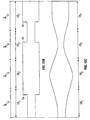
Curve 71, representing a conventional waveguide system, shows asignificant output dip 74 at about 350 Hz, and similar dips at integer multiples of about 350 Hz. Dashedcurve 72, representing a waveguide system (not shown) resulting from a superimposition onto the waveguide of FIG. 7a of a waveguide according to FIG. 4, with n = 16, with the length of each segment x/16, shows that the output dips at the cancellation frequency, the even multiples of the cancellation frequency, at the odd multiples of the cancellation frequency, at two times the odd multiples of the cancellation frequency, and at four times the odd multiples of the cancellation frequency have been significantly reduced. - As n gets large, the superimposed waveguide begins to approach the waveguide shown in FIG.10. In FIG.10, the waveguide has two sections of length x/2. The walls of the waveguide are configured such that the cross-sectional area at the beginning of each section is
log e 3 / 2A , and increases tolog e 3 / 2A (3) (where y is distance betweentransducer end 12 of the waveguide, x is the length of the waveguide, andA is the average cross-sectional area of the waveguide). - Referring to FIG. 11, there is shown a waveguide with standing waves helpful in determining the length of the sections. FIG. 11 shows a parallel sided waveguide with a standing
wave 80 formed when sound waves are radiated into the waveguide. Standingwave 80 has a tuning frequency f and a corresponding wavelength λ that is equal to the length x of the waveguide. Standingwave 80 represents the pressure at points along the length of waveguide.Pressure standing wave 80 has pressure nulls 82, 84 at the transducer and at the opening of the waveguide, respectively and another null 86 at a point approximately half way between the transducer and the opening. Standingwave 88, formed when sound waves are radiated into the waveguide, represents the volume velocity at points along the length of the waveguide. Volumevelocity standing wave 88 has volume velocity nulls 92, 94 between pressure nulls 82 and 86 and between pressure nulls 86 and 84, respectively, approximately equidistant from the pressure nulls. In one embodiment of the invention, a waveguide as shown in FIG. 5a (shown in this figure in dotted lines) has four sections, the beginning and the end of the sections is determined by the location of the volume velocity nulls and the pressure nulls of a waveguide with parallel walls and the same average cross-sectional area. First section 18- ends andsecond section 182 begins atvolume velocity null 92;second section 182 ends andthird section 183 begins atpressure null 86;third section 183 ends andfourth section 184 begins atvolume velocity null 94. In a straight walled waveguide, the distance between the first pressure null and the first volume velocity null, between the first volume velocity null and the second pressure null, between the second pressure null and that second volume velocity null, and between the second volume velocity null and the third pressure null are all equal, so that the lengths x1 ... X4 of thesections 181 ... 184 are all approximately one fourth of the length of the waveguide. - In addition to the standing wave of frequency f and wavelength λ, there may exist in the waveguide standing waves of frequency 2f, 4f, 8f, ... nf with corresponding wavelengths of λ/2, λ/4, λ/8, ...λ/n. A standing wave of frequency 2f has five pressure nulls. In a parallel sided waveguide, there will be one pressure null at each end of the waveguide, with the remaining pressure nulls spaced equidistantly along the length of the waveguide. A standing wave of frequency 2f has four volume velocity nulls, between the pressure nulls, and spaced equidistantly between the pressure nulls. Similarly, standing waves of frequencies 4f, 8f,... nf with corresponding wavelengths of λ/4, λ/8, ... λ/n have 2n+1 pressure nulls and 2n volume velocity nulls, spaced similarly to the standing wave of frequency 2f and the wavelength of λ/2. Similar standing waves are formed in waveguides the do not have parallel sides, but the location of the nulls may not be evenly spaced. The location of the nulls may be determined empirically.
- Referring to FIGS. 12a- 12c, there are shown other embodiments illustrating other principles of the invention. FIG. 12a illustrates the principle that adjacent segments having a length equal to the sections of FIG. 11 may have the same cross-sectional area, and still provide the advantages of the invention. In FIG. 12a, the lengths of the segments are determined in the same manner as the sections of FIG. 11. Some adjacent sections have the same cross-sectional areas, and at least one of the segments has a larger cross-sectional area than adjacent segments. The cross-sectional areas may be selected such that
A A A - Referring now to FIG. 12b, there is illustrated another principle of the invention. In this embodiment, changes 19 in the cross-sectional area do not occur at the points shown in FIG. 11 and described in the accompanying portion of the disclosure. However, if the cross-sectional area of
segments 181 182, 183, and 184 follow the relationshipA segments - Referring now to FIG. 12c, there is illustrated yet another aspect of the invention. In this embodiment, the cross-sectional area does not change abruptly, but rather changes smoothly according to a sinusoidal or other smooth function. Similar to the embodiment of FIG. 12b, however, if the cross-sectional area of
segments A sections - Referring now to FIG. 13, there is shown an embodiment of the invention that combines the principles of the embodiments of FIGS. 1 and 4. An
electroacoustical transducer 10 is positioned in an end of an open-ended waveguide 14'. In one embodiment of the invention,electroacoustical transducer 10 is a cone and magnet transducer or some other electroacoustical transducer, such as electrostatic, piezoelectric or other source of acoustic waves.Electroacoustical transducer 10 may face either end of waveguide 14', or may be mounted in a wall of waveguide 14' and radiate sound waves into waveguide 14'.Cavity 17 in whichelectroacoustical transducer 10 is positioned closely conforms to electroacousticaltransducer 10. Interior walls of waveguide 14' are essentially smooth and acoustically lossless. In waveguide 14' may be a small amount of acoustically absorbingmaterial 13, so that the waveguide is low loss acoustically. The small amount of acoustically absorbing material damps undesirable resonances and provides a smoother output over the range of frequencies radiated by the waveguide system but does not prevent the formation of low frequency standing waves in the waveguide. - Waveguide 14' has a plurality of
sections sections 181 182, ... 18n has a length x1, x2 ... xn and a cross-sectional area A1, A2 ...An. Each of the sections has a cross-sectional area at end closest to theelectroacoustical transducer 10 that is larger than the end farthest from the electroacoustical transducer. In this implementation, changes 19 in the cross-sectional area are shown as abrupt. In an actual implementation, the changes in cross-sectional area may be gradual. - A waveguide according to the embodiment of FIG. 13 combines the advantages of the embodiments of FIGS. I and 4. The waveguide end cancellation problem is significantly reduced, and flatter frequency response can be realized with a waveguide system according to FIG. 13 than with a conventional waveguide.
- Referring to FIGS. 14a - 14c, there are shown waveguide systems similar to the embodiments of FIGS. 7a, 8a, and 9a, but with narrowing cross-sectional areas toward the right. As with the embodiments of FIGS. 7a, 8a, and 9a end cancellation position problem is significantly reduced; additionally an acoustic performance equivalent to loudspeaker assemblies having longer waveguides can be realized.
- A waveguide as shown in FIGS. 14a- 14c has sections beginning and ending at similar places relative to the pressure nulls and volume velocity nulls, but the nulls may not be evenly placed as in the parallel sided waveguide. In waveguides as shown in FIGS. 14a - 14c, the location of the nulls may be determined empirically or by computer modeling.
In waveguides as shown in FIG. 14a- 14c, as n becomes large, the waveguide begins to approach the shape of waveguides described by the formula
where:
(i.e. the area ratio) - Examples of such waveguides are shown in FIGS. 1 5a (AR = 4) and 15b (AR = 9) . It can be noted that in if the area ratio is 1 (indicating an untapered waveguide) the waveguide is as shown in FIG. 10 and described in the accompanying text.
Other embodiments are within the claims.
Claims (32)
- A waveguide system for radiating sound waves, comprising:a low loss acoustic waveguide for transmitting sound waves, said waveguide comprisinga first terminus adapted to be coupled to a source of sound waves;a second terminus adapted to radiate said sound waves to the external environment;a centerline running the length of said waveguide;walls enclosing cross-sectional areas in planes perpendicular to said centerline;wherein said walls are tapered such that the cross-sectional area at said second terminus is less than the cross-sectional area at said first terminus.
- A waveguide system in accordance with claim 1, wherein said cross-sectional areas progressively decrease as a function of distance from said first terminus.
- A waveguide in accordance with claim 2, wherein said cross-sectional areas vary according to a formulawhere A is the cross-sectional area, Ainlet is the cross-sectional area at said first terminus, y is the distance measured from said first terminus, and

- A waveguide system in accordance with claim 1, wherein the cross-sectional area at said second terminus is less than one half the cross-sectional area at said first terminus.
- A waveguide system in accordance with claim 4, wherein the cross-sectional area at said second terminus is on the order of one seventh of the cross-sectional at said first terminus.
- A waveguide system for radiating sound waves, comprising:a low loss waveguide for transmitting sound waves, said waveguide comprisinga first terminus adapted to be coupled to a source of said sound waves;a second terminus adapted to radiate said sound waves to the external environment;a centerline;walls enclosing cross-sectional areas in planes perpendicular to said centerline;a plurality of sections, along the length of said centerline, each of said sections having a first end and a second end, said first end nearer said first terminus and said second end nearer said second terminus, each of said sections having an average crosssectional area;wherein a first of said plurality of sections and a second of said plurality of sections are constructed and arranged such that there is a mating of said second end of said first section to said first end of said second section; andwherein the cross-sectional area at said second end of said first section has a substantially different cross-sectional area from that at the first end of said second section.
- A waveguide system in accordance with claim 6, wherein said average crosssectional area of said first section is substantially different from the average crosssectional area of said second section.
- A waveguide in accordance with claim 6 wherein the cross-sectional area of said first section is substantially constant.
- A waveguide in accordance with claim 7 wherein the cross-sectional area of said second section is substantially constant.
- A waveguide system in accordance with claim 6 wherein there are an even number of sections.
- A waveguide system in accordance with claim 10 wherein a product of the average cross-sectional areas of a first set of alternating sections is approximately three times the product of the average cross-sectional areas of a second set of alternating sections.
- A waveguide system in accordance with claim 6 wherein said walls are tapered such that the cross-sectional area of said second end of said first section is less than the cross-sectional area of said first end of said first section.
- A waveguide system in accordance with claim 6 wherein said walls are tapered such that the cross-sectional area of said second end of said second section is less than the cross-sectional area of said first end of said second section.
- A waveguide system in accordance with claim 6 wherein said walls are tapered such that the cross-sectional area at said second ends of said first section and of the second section are less than the cross-sectional area at said first ends of said first section and of said second section.
- A waveguide system in accordance with claim 6, wherein said waveguide is constructed and arranged to form a standing pressure wave having a wavelength substantially equal to the effective length I of said low loss waveguide, said standing pressure wave having nulls, and wherein said mating is positioned so that it coincides with one of said pressure nulls.
- A waveguide system in accordance with claim 15 wherein said wavelength is substantially equal towhere n is an integer greater than one.

- A waveguide system in accordance with claim 6, wherein said waveguide is constructed and arranged to form a standing volume velocity wave having a wavelength substantially equal to the effective length 1 of said low loss waveguide, said volume velocity standing wave having nulls, and wherein said mating is positioned so that it coincides with one of said volume velocity nulls.
- A waveguide system in accordance with claim 17 wherein said wavelength is substantially equal towhere n is an integer greater than one.

- A waveguide system in accordance with claim 6, wherein said waveguide has a resonant frequency, said frequency having an associated wave length λ, and wherein the length of each of said plurality of sections is approximately equal towhere n is an integer

- A waveguide system for radiating sound waves, composing:a low loss waveguide for transmitting sound waves, said waveguide comprisinga first terminus adapted to be coupled to a source of said sound waves;a second terminus adapted to radiate said sound waves to the external environment;a centerline, ranning the length of said waveguide;walls enclosing cross-sectional areas in planes perpendicular to said centerline;a plurality of sections, along the length of said centerline, each of said sections having a first end and a second end, said first end nearer said first terminus and said second end nearer said second terminus;wherein a first of said plurality of sections and a second of said plurality of sections are constructed and arranged such that there is a mating of said second end of said first section to said first end of said second section;wherein the cross-sectional area of said first section increases from said first end to said second end according to a first exponential function andwherein the cross-sectional area at said second end of said first section is larger than the cross-sectional area at said first end of said second section.
- A waveguide system in accordance with claim 20, wherein said crosssectional area of said second section increases from said first end to said second end t according to a first exponential function.
- A waveguide system in accordance with claim 20, wherein said crosssectional area of said second section increases from said first end to said second end according to a second exponential function.
- A waveguide system for radiating sound waves, comprising: a low loss waveguide for transmitting sound waves having a tuning frequency, said frequency having a corresponding wavelength, said waveguide comprising a centerline, running the length of said waveguide;walls enclosing cross-sectional areas in planes perpendicular to said centerline;a plurality of sections, along said centerline, each of said sections having a length of approximately one fourth of said wavelength, each of said sections having an average cross-sectional area;wherein the average cross-sectional area of a first of said plurality of sections is different from the average cross-sectional area of an adjacent one of said plurality of sections.
- A waveguide system in accordance with claim 23 wherein the cross-sectional area of said first section is substantially constant.
- A waveguide system in accordance with claim 24 wherein the cross-sectional area of said adjacent section is substantially constant.
- A waveguide system in accordance with claim 23 wherein a product of said average cross-sectional areas of a first set of alternating sections is approximately three times a product of said average cross-sectional areas of a second set of alternating sections.
- A waveguide system for radiating sound waves, said waveguide having segments of length approximately equal towhere l is the effective length of said waveguide and n is a positive integer, each of said segments having an average cross-sectional area, wherein a product of the average cross-sectional areas of a first set of alternating segments is greater than two times a product of the average cross-sectional areas of a second set of alternating segments.

- A waveguide system in accordance with claim 27 wherein said product of said average cross-sectional areas of said first set of alternating segments is approximately three times said average cross-sectional area of said second set of alternating segments.
- A waveguide m accordance with claim 27, wherein one of said segments has an average cross-sectional area greater than the cross-sectional area of either of the adjacent segments.
- A waveguide for radiating sound waves, constructed and arranged to form standing pressure waves and standing volume velocity waves,said volume velocity standing wave having a wavelength substantially equal to the effective length I of said waveguide, said volume velocity standing wave having volume velocity nulls;said pressure standing wave having a wavelength substantially equal to the effective length l of said waveguide, said pressure standing wave having pressure nulls,said pressure nulls occurring between said volume velocity nulls;said volume velocity nulls and said pressure nulls delimiting a plurality of segments of said waveguide, each of said segments having an average cross-sectional area; andwherein a product of the average cross-sectional areas of a first set of alternating segments is greater than two times a product of the average cross-sectional areas of a second set of alternating segments
- A waveguide in accordance with claim 30 wherein said product of said average cross-sectional areas of said first set of alternating segments is approximately three times said average cross-sectional area of said second set of alternating segments.
- A waveguide in accordance with claim 30, wherein one of said segments has an average cross-sectional area greater than either of the adjacent segments.
Priority Applications (1)
| Application Number | Priority Date | Filing Date | Title |
|---|---|---|---|
| EP02026327A EP1284585B1 (en) | 1998-09-03 | 1999-08-27 | Electroacoustic waveguide |
Applications Claiming Priority (2)
| Application Number | Priority Date | Filing Date | Title |
|---|---|---|---|
| US146662 | 1993-11-01 | ||
| US09/146,662 US6771787B1 (en) | 1998-09-03 | 1998-09-03 | Waveguide electroacoustical transducing |
Related Child Applications (1)
| Application Number | Title | Priority Date | Filing Date |
|---|---|---|---|
| EP02026327A Division EP1284585B1 (en) | 1998-09-03 | 1999-08-27 | Electroacoustic waveguide |
Publications (3)
| Publication Number | Publication Date |
|---|---|
| EP0984662A2 true EP0984662A2 (en) | 2000-03-08 |
| EP0984662A3 EP0984662A3 (en) | 2001-04-11 |
| EP0984662B1 EP0984662B1 (en) | 2004-07-07 |
Family
ID=22518408
Family Applications (2)
| Application Number | Title | Priority Date | Filing Date |
|---|---|---|---|
| EP99306839A Expired - Lifetime EP0984662B1 (en) | 1998-09-03 | 1999-08-27 | Waveguide electroacoustical transducing |
| EP02026327A Expired - Lifetime EP1284585B1 (en) | 1998-09-03 | 1999-08-27 | Electroacoustic waveguide |
Family Applications After (1)
| Application Number | Title | Priority Date | Filing Date |
|---|---|---|---|
| EP02026327A Expired - Lifetime EP1284585B1 (en) | 1998-09-03 | 1999-08-27 | Electroacoustic waveguide |
Country Status (6)
| Country | Link |
|---|---|
| US (3) | US6771787B1 (en) |
| EP (2) | EP0984662B1 (en) |
| JP (1) | JP4417489B2 (en) |
| CN (2) | CN101026895B (en) |
| DE (1) | DE69918502T2 (en) |
| HK (1) | HK1108265A1 (en) |
Cited By (2)
| Publication number | Priority date | Publication date | Assignee | Title |
|---|---|---|---|---|
| EP1221823A2 (en) | 2001-01-02 | 2002-07-10 | Bose Corporation | Electroacoustic waveguide transducing |
| GB2590656A (en) * | 2019-12-23 | 2021-07-07 | Gp Acoustics International Ltd | Loudspeakers |
Families Citing this family (37)
| Publication number | Priority date | Publication date | Assignee | Title |
|---|---|---|---|---|
| US6771787B1 (en) * | 1998-09-03 | 2004-08-03 | Bose Corporation | Waveguide electroacoustical transducing |
| ATE448648T1 (en) * | 2000-09-22 | 2009-11-15 | Robert Michael Grunberg | DIRECT COUPLING OF WAVEGUIDES TO A COMPRESSION DRIVER WITH MATCHING SLOT-SHAPED NECKS |
| US7457425B2 (en) * | 2001-02-09 | 2008-11-25 | Thx Ltd. | Vehicle sound system |
| US7254239B2 (en) * | 2001-02-09 | 2007-08-07 | Thx Ltd. | Sound system and method of sound reproduction |
| US7433483B2 (en) | 2001-02-09 | 2008-10-07 | Thx Ltd. | Narrow profile speaker configurations and systems |
| FR2824990B1 (en) * | 2001-05-15 | 2003-09-26 | Jean Pierre Morkerken | SOUND TRANSMITTER AND SPEAKER |
| AU2003232181A1 (en) * | 2002-07-12 | 2004-02-02 | Oticon A/S | Suspension means for transducer |
| DE60233270D1 (en) * | 2002-10-10 | 2009-09-17 | Nokia Corp | SOUND PRODUCTION DEVICE, MOBILE ELECTRICAL EQUIPMENT AND SYSTEM FOR GENERATING SOUND |
| US7676047B2 (en) | 2002-12-03 | 2010-03-09 | Bose Corporation | Electroacoustical transducing with low frequency augmenting devices |
| US7218747B2 (en) * | 2003-12-05 | 2007-05-15 | Nick Huffman | Externally ported loudspeaker enclosure |
| US20070206828A1 (en) * | 2004-04-01 | 2007-09-06 | Koninklijke Philips Electronics, N.V. | Distributed acoustic cabinet |
| US7549509B2 (en) * | 2005-04-21 | 2009-06-23 | Ingersoll-Rand Company | Double throat pulsation dampener for a compressor |
| US20080212807A1 (en) * | 2005-06-08 | 2008-09-04 | General Mems Corporation | Micromachined Acoustic Transducers |
| WO2006135625A2 (en) * | 2005-06-09 | 2006-12-21 | Schultz Roland P | Driver and enclosure combination |
| US7606383B2 (en) * | 2005-10-05 | 2009-10-20 | Qsc Audio Products, Inc. | Curved line array loudspeaker |
| CA2720185A1 (en) | 2007-10-22 | 2009-04-30 | David Maeshiba | Acoustic system |
| US8295526B2 (en) | 2008-02-21 | 2012-10-23 | Bose Corporation | Low frequency enclosure for video display devices |
| US8351629B2 (en) * | 2008-02-21 | 2013-01-08 | Robert Preston Parker | Waveguide electroacoustical transducing |
| US8615097B2 (en) | 2008-02-21 | 2013-12-24 | Bose Corportion | Waveguide electroacoustical transducing |
| US8351630B2 (en) | 2008-05-02 | 2013-01-08 | Bose Corporation | Passive directional acoustical radiating |
| JP2010093485A (en) * | 2008-10-07 | 2010-04-22 | Casio Hitachi Mobile Communications Co Ltd | Waterproof speaker, electronic equipment, and waterproof sound generating device |
| US8002078B2 (en) * | 2009-02-19 | 2011-08-23 | Bose Corporation | Acoustic waveguide vibration damping |
| WO2011031794A2 (en) * | 2009-09-08 | 2011-03-17 | Clements Philip R | Inverse horn loudspeakers |
| US8401216B2 (en) * | 2009-10-27 | 2013-03-19 | Saab Sensis Corporation | Acoustic traveling wave tube system and method for forming and propagating acoustic waves |
| US8265310B2 (en) * | 2010-03-03 | 2012-09-11 | Bose Corporation | Multi-element directional acoustic arrays |
| US8553894B2 (en) | 2010-08-12 | 2013-10-08 | Bose Corporation | Active and passive directional acoustic radiating |
| CN102883252A (en) * | 2011-07-14 | 2013-01-16 | 上海一诺仪表有限公司 | Cone-shaped ultra-waveguide vibrator of ultrasonic transducer |
| US9204211B2 (en) | 2011-12-16 | 2015-12-01 | Avnera Corporation | Pad-type device case providing enhanced audio functionality and output |
| US9173018B2 (en) | 2012-06-27 | 2015-10-27 | Bose Corporation | Acoustic filter |
| EP2974356B1 (en) | 2013-03-13 | 2020-05-06 | THX Ltd | Slim profile loudspeaker |
| US9754578B2 (en) | 2014-01-09 | 2017-09-05 | Dolby Laboratories Licensing Corporation | Loudspeaker horn and cabinet |
| US9451355B1 (en) | 2015-03-31 | 2016-09-20 | Bose Corporation | Directional acoustic device |
| US10057701B2 (en) | 2015-03-31 | 2018-08-21 | Bose Corporation | Method of manufacturing a loudspeaker |
| WO2017196631A1 (en) * | 2016-05-10 | 2017-11-16 | Bose Corporation | Acoustic device |
| US9749735B1 (en) * | 2016-07-06 | 2017-08-29 | Bose Corporation | Waveguide |
| DE102017214404B4 (en) * | 2017-08-18 | 2023-12-28 | Audi Ag | Speaker arrangement and vehicle |
| WO2019107781A1 (en) | 2017-11-28 | 2019-06-06 | Samsung Electronics Co., Ltd. | Loudspeaker and sound outputting apparatus having the same |
Citations (5)
| Publication number | Priority date | Publication date | Assignee | Title |
|---|---|---|---|---|
| FR1359616A (en) * | 1960-07-05 | 1964-04-30 | Csf | New acoustic wave projector |
| FR2653630A1 (en) * | 1989-10-23 | 1991-04-26 | Scotto Di Carlo Gilles | Acoustic enclosure structure |
| US5373564A (en) * | 1992-10-02 | 1994-12-13 | Spear; Robert J. | Transmission line for planar waves |
| WO1996011558A1 (en) * | 1994-10-10 | 1996-04-18 | A/S Brüel & Kjær | Omnidirectional sound source |
| WO1998020659A1 (en) * | 1996-11-07 | 1998-05-14 | Ericsson, Inc. | Radiotelephone having an acoustical wave guide coupled to a speaker |
Family Cites Families (37)
| Publication number | Priority date | Publication date | Assignee | Title |
|---|---|---|---|---|
| US1755636A (en) * | 1927-09-22 | 1930-04-22 | Radio Patents Corp | Loud-speaker |
| US2293181A (en) * | 1940-07-17 | 1942-08-18 | Int Standard Electric Corp | Sound absorbing apparatus |
| US3486578A (en) * | 1967-12-21 | 1969-12-30 | Lawrence Albarino | Electro-mechanical reproduction of sound |
| SE358800B (en) * | 1972-02-29 | 1973-08-06 | Bostedt J | |
| US3940576A (en) * | 1974-03-19 | 1976-02-24 | Schultz Herbert J | Loudspeaker having sound funnelling element |
| US4340778A (en) | 1979-11-13 | 1982-07-20 | Bennett Sound Corporation | Speaker distortion compensator |
| US4628528A (en) * | 1982-09-29 | 1986-12-09 | Bose Corporation | Pressure wave transducing |
| US4930596A (en) * | 1987-06-16 | 1990-06-05 | Matsushita Electric Industrial Co., Ltd. | Loudspeaker system |
| US5012890A (en) * | 1988-03-23 | 1991-05-07 | Yamaha Corporation | Acoustic apparatus |
| EP0477256B1 (en) * | 1989-06-12 | 1993-08-25 | Josef Gail | Piston engine |
| US5105905A (en) * | 1990-05-07 | 1992-04-21 | Rice Winston C | Co-linear loudspeaker system |
| US5740259A (en) * | 1992-06-04 | 1998-04-14 | Bose Corporation | Pressure wave transducing |
| US6002781A (en) * | 1993-02-24 | 1999-12-14 | Matsushita Electric Industrial Co., Ltd. | Speaker system |
| US6278789B1 (en) * | 1993-05-06 | 2001-08-21 | Bose Corporation | Frequency selective acoustic waveguide damping |
| AU666616B2 (en) * | 1993-06-30 | 1996-02-15 | Sanyo Electric Co., Ltd. | Microwave oven including antenna for radiating microwave |
| US5481385A (en) * | 1993-07-01 | 1996-01-02 | Alliedsignal Inc. | Direct view display device with array of tapered waveguide on viewer side |
| GB2295518B (en) * | 1994-12-23 | 1998-08-05 | Graeme John Huon | Loudspeaker system incorporating acoustic waveguide filters and method of construction |
| US5673329A (en) * | 1995-03-23 | 1997-09-30 | Wiener; David | Omni-directional loudspeaker system |
| US5644109A (en) * | 1995-05-30 | 1997-07-01 | Newman; Ottis G. | Speaker enclosure |
| US5828759A (en) | 1995-11-30 | 1998-10-27 | Siemens Electric Limited | System and method for reducing engine noise |
| US5821471A (en) | 1995-11-30 | 1998-10-13 | Mcculler; Mark A. | Acoustic system |
| US5832099A (en) * | 1997-01-08 | 1998-11-03 | Wiener; David | Speaker system having an undulating rigid speaker enclosure |
| US5815589A (en) * | 1997-02-18 | 1998-09-29 | Wainwright; Charles E. | Push-pull transmission line loudspeaker |
| JPH11220789A (en) | 1998-01-30 | 1999-08-10 | Sony Corp | Electrical acoustic conversion device |
| US6144751A (en) * | 1998-02-24 | 2000-11-07 | Velandia; Erich M. | Concentrically aligned speaker enclosure |
| US6771787B1 (en) * | 1998-09-03 | 2004-08-03 | Bose Corporation | Waveguide electroacoustical transducing |
| DE19861018C2 (en) * | 1998-12-15 | 2001-06-13 | Fraunhofer Ges Forschung | Controlled acoustic waveguide for sound absorption |
| US6374120B1 (en) * | 1999-02-16 | 2002-04-16 | Denso Corporation | Acoustic guide for audio transducers |
| US6704425B1 (en) * | 1999-11-19 | 2004-03-09 | Virtual Bass Technologies, Llc | System and method to enhance reproduction of sub-bass frequencies |
| US6431309B1 (en) * | 2000-04-14 | 2002-08-13 | C. Ronald Coffin | Loudspeaker system |
| JP4240795B2 (en) * | 2000-10-10 | 2009-03-18 | コニカミノルタビジネステクノロジーズ株式会社 | Image forming system, image forming apparatus, and job data processing method |
| US7426280B2 (en) * | 2001-01-02 | 2008-09-16 | Bose Corporation | Electroacoustic waveguide transducing |
| US6662627B2 (en) * | 2001-06-22 | 2003-12-16 | Desert Research Institute | Photoacoustic instrument for measuring particles in a gas |
| US6820431B2 (en) * | 2002-10-31 | 2004-11-23 | General Electric Company | Acoustic impedance-matched fuel nozzle device and tunable fuel injection resonator assembly |
| US6792907B1 (en) * | 2003-03-04 | 2004-09-21 | Visteon Global Technologies, Inc. | Helmholtz resonator |
| JP2006125381A (en) * | 2004-09-29 | 2006-05-18 | Toyoda Gosei Co Ltd | Resonator |
| DE102007039598B4 (en) * | 2006-09-05 | 2010-07-22 | DENSO CORPORATION, Kariya-shi | Ultrasonic sensor and obstacle detector device |
-
1998
- 1998-09-03 US US09/146,662 patent/US6771787B1/en not_active Expired - Lifetime
-
1999
- 1999-08-27 DE DE1999618502 patent/DE69918502T2/en not_active Expired - Lifetime
- 1999-08-27 EP EP99306839A patent/EP0984662B1/en not_active Expired - Lifetime
- 1999-08-27 EP EP02026327A patent/EP1284585B1/en not_active Expired - Lifetime
- 1999-09-03 JP JP25030999A patent/JP4417489B2/en not_active Expired - Lifetime
- 1999-09-03 CN CN200710089694.0A patent/CN101026895B/en not_active Expired - Lifetime
- 1999-09-03 CN CN99118610A patent/CN1258185A/en active Pending
-
2000
- 2000-12-28 HK HK08102029.3A patent/HK1108265A1/en not_active IP Right Cessation
-
2004
- 2004-06-11 US US10/866,566 patent/US7623670B2/en not_active Expired - Lifetime
-
2009
- 2009-10-09 US US12/576,274 patent/US20100092019A1/en not_active Abandoned
Patent Citations (5)
| Publication number | Priority date | Publication date | Assignee | Title |
|---|---|---|---|---|
| FR1359616A (en) * | 1960-07-05 | 1964-04-30 | Csf | New acoustic wave projector |
| FR2653630A1 (en) * | 1989-10-23 | 1991-04-26 | Scotto Di Carlo Gilles | Acoustic enclosure structure |
| US5373564A (en) * | 1992-10-02 | 1994-12-13 | Spear; Robert J. | Transmission line for planar waves |
| WO1996011558A1 (en) * | 1994-10-10 | 1996-04-18 | A/S Brüel & Kjær | Omnidirectional sound source |
| WO1998020659A1 (en) * | 1996-11-07 | 1998-05-14 | Ericsson, Inc. | Radiotelephone having an acoustical wave guide coupled to a speaker |
Cited By (3)
| Publication number | Priority date | Publication date | Assignee | Title |
|---|---|---|---|---|
| EP1221823A2 (en) | 2001-01-02 | 2002-07-10 | Bose Corporation | Electroacoustic waveguide transducing |
| GB2590656A (en) * | 2019-12-23 | 2021-07-07 | Gp Acoustics International Ltd | Loudspeakers |
| US11647326B2 (en) | 2019-12-23 | 2023-05-09 | Gp Acoustics International Limited | Loudspeakers |
Also Published As
| Publication number | Publication date |
|---|---|
| DE69918502T2 (en) | 2004-11-18 |
| US6771787B1 (en) | 2004-08-03 |
| US7623670B2 (en) | 2009-11-24 |
| EP0984662A3 (en) | 2001-04-11 |
| EP0984662B1 (en) | 2004-07-07 |
| CN101026895B (en) | 2014-01-29 |
| CN1258185A (en) | 2000-06-28 |
| CN101026895A (en) | 2007-08-29 |
| DE69918502D1 (en) | 2004-08-12 |
| US20050036642A1 (en) | 2005-02-17 |
| EP1284585B1 (en) | 2011-10-05 |
| HK1108265A1 (en) | 2008-05-02 |
| JP4417489B2 (en) | 2010-02-17 |
| US20100092019A1 (en) | 2010-04-15 |
| JP2000092583A (en) | 2000-03-31 |
| EP1284585A1 (en) | 2003-02-19 |
Similar Documents
| Publication | Publication Date | Title |
|---|---|---|
| EP0984662A2 (en) | Waveguide electroacoustical transducing | |
| US8175311B2 (en) | Electroacoustic waveguide transducing | |
| EP1178702B1 (en) | Wave shaping sound chamber | |
| US6094495A (en) | Horn-type loudspeaker system | |
| US20060285712A1 (en) | Coaxial mid-frequency and high-frequency loudspeaker | |
| US4629029A (en) | Multiple driver manifold | |
| EP1333698A2 (en) | Directional loudspeaker unit | |
| EP1410683B1 (en) | Speaker port system for reducing boundary layer separation | |
| KR20010074943A (en) | Panel form acoustic apparatus using bending waves modes | |
| JPH05268690A (en) | Loud speaker unit having wide-angle directivity | |
| US8615097B2 (en) | Waveguide electroacoustical transducing | |
| US20030042068A1 (en) | Structure for preventing the generation of standing waves and a method for implementing the same | |
| KR20010083946A (en) | Loudspeakers Comprising a Phase Uncorrelated Diffuse Sound Source | |
| EP3486898B1 (en) | Compression driver with side-firing compression chamber | |
| US6334505B1 (en) | Optimum edges for speakers and musical instruments | |
| JP3267999B2 (en) | Speaker system | |
| US11647326B2 (en) | Loudspeakers | |
| US2805728A (en) | Sound dispersion device with internal divergent acoustical lens | |
| JPH01279698A (en) | Speaker system | |
| JPH05137188A (en) | Speaker system | |
| JPH0775431B2 (en) | Speaker system |
Legal Events
| Date | Code | Title | Description |
|---|---|---|---|
| PUAI | Public reference made under article 153(3) epc to a published international application that has entered the european phase |
Free format text: ORIGINAL CODE: 0009012 |
|
| AK | Designated contracting states |
Kind code of ref document: A2 Designated state(s): DE FR |
|
| AX | Request for extension of the european patent |
Free format text: AL;LT;LV;MK;RO;SI |
|
| PUAL | Search report despatched |
Free format text: ORIGINAL CODE: 0009013 |
|
| AK | Designated contracting states |
Kind code of ref document: A3 Designated state(s): AT BE CH CY DE DK ES FI FR GB GR IE IT LI LU MC NL PT SE |
|
| AX | Request for extension of the european patent |
Free format text: AL;LT;LV;MK;RO;SI |
|
| RIC1 | Information provided on ipc code assigned before grant |
Free format text: 7H 04R 1/32 A, 7H 04R 1/28 B |
|
| 17P | Request for examination filed |
Effective date: 20011002 |
|
| AKX | Designation fees paid |
Free format text: DE FR |
|
| 17Q | First examination report despatched |
Effective date: 20020725 |
|
| GRAP | Despatch of communication of intention to grant a patent |
Free format text: ORIGINAL CODE: EPIDOSNIGR1 |
|
| GRAS | Grant fee paid |
Free format text: ORIGINAL CODE: EPIDOSNIGR3 |
|
| GRAA | (expected) grant |
Free format text: ORIGINAL CODE: 0009210 |
|
| AK | Designated contracting states |
Kind code of ref document: B1 Designated state(s): DE FR |
|
| REF | Corresponds to: |
Ref document number: 69918502 Country of ref document: DE Date of ref document: 20040812 Kind code of ref document: P |
|
| ET | Fr: translation filed | ||
| PLBE | No opposition filed within time limit |
Free format text: ORIGINAL CODE: 0009261 |
|
| STAA | Information on the status of an ep patent application or granted ep patent |
Free format text: STATUS: NO OPPOSITION FILED WITHIN TIME LIMIT |
|
| 26N | No opposition filed |
Effective date: 20050408 |
|
| REG | Reference to a national code |
Ref country code: FR Ref legal event code: PLFP Year of fee payment: 18 |
|
| REG | Reference to a national code |
Ref country code: FR Ref legal event code: PLFP Year of fee payment: 19 |
|
| REG | Reference to a national code |
Ref country code: FR Ref legal event code: PLFP Year of fee payment: 20 |
|
| PGFP | Annual fee paid to national office [announced via postgrant information from national office to epo] |
Ref country code: DE Payment date: 20180829 Year of fee payment: 20 Ref country code: FR Payment date: 20180827 Year of fee payment: 20 |
|
| REG | Reference to a national code |
Ref country code: DE Ref legal event code: R082 Ref document number: 69918502 Country of ref document: DE |
|
| REG | Reference to a national code |
Ref country code: DE Ref legal event code: R071 Ref document number: 69918502 Country of ref document: DE |