EP0984580A2 - Skalierbare optische Demultiplexing-Vorrichtung für breitbandige dichte Wellenlängenmultiplexsysteme - Google Patents
Skalierbare optische Demultiplexing-Vorrichtung für breitbandige dichte Wellenlängenmultiplexsysteme Download PDFInfo
- Publication number
- EP0984580A2 EP0984580A2 EP99306644A EP99306644A EP0984580A2 EP 0984580 A2 EP0984580 A2 EP 0984580A2 EP 99306644 A EP99306644 A EP 99306644A EP 99306644 A EP99306644 A EP 99306644A EP 0984580 A2 EP0984580 A2 EP 0984580A2
- Authority
- EP
- European Patent Office
- Prior art keywords
- optical
- channels
- demultiplexer
- filters
- wavelength
- Prior art date
- Legal status (The legal status is an assumption and is not a legal conclusion. Google has not performed a legal analysis and makes no representation as to the accuracy of the status listed.)
- Withdrawn
Links
- 230000003287 optical effect Effects 0.000 title claims abstract description 154
- 230000003595 spectral effect Effects 0.000 claims abstract description 28
- 238000001914 filtration Methods 0.000 claims abstract description 19
- 239000002131 composite material Substances 0.000 claims description 8
- 238000000034 method Methods 0.000 claims description 5
- 230000005540 biological transmission Effects 0.000 claims description 3
- 239000010409 thin film Substances 0.000 claims description 2
- 230000002452 interceptive effect Effects 0.000 claims 1
- 238000000638 solvent extraction Methods 0.000 abstract description 6
- 230000009467 reduction Effects 0.000 abstract description 5
- 238000005192 partition Methods 0.000 abstract description 2
- 238000005516 engineering process Methods 0.000 description 10
- 238000001228 spectrum Methods 0.000 description 5
- 230000000694 effects Effects 0.000 description 4
- 238000004891 communication Methods 0.000 description 3
- 238000013461 design Methods 0.000 description 3
- 239000000470 constituent Substances 0.000 description 2
- 229910052710 silicon Inorganic materials 0.000 description 2
- 239000010703 silicon Substances 0.000 description 2
- 101100013508 Gibberella fujikuroi (strain CBS 195.34 / IMI 58289 / NRRL A-6831) FSR1 gene Proteins 0.000 description 1
- XUIMIQQOPSSXEZ-UHFFFAOYSA-N Silicon Chemical compound [Si] XUIMIQQOPSSXEZ-UHFFFAOYSA-N 0.000 description 1
- 230000008901 benefit Effects 0.000 description 1
- 230000008878 coupling Effects 0.000 description 1
- 238000010168 coupling process Methods 0.000 description 1
- 238000005859 coupling reaction Methods 0.000 description 1
- 239000000835 fiber Substances 0.000 description 1
- 238000004519 manufacturing process Methods 0.000 description 1
- 238000012986 modification Methods 0.000 description 1
- 230000004048 modification Effects 0.000 description 1
- 238000012544 monitoring process Methods 0.000 description 1
- 230000006855 networking Effects 0.000 description 1
- 239000013307 optical fiber Substances 0.000 description 1
- 238000000746 purification Methods 0.000 description 1
- 238000000926 separation method Methods 0.000 description 1
- 230000001629 suppression Effects 0.000 description 1
Images


Classifications
-
- H—ELECTRICITY
- H04—ELECTRIC COMMUNICATION TECHNIQUE
- H04J—MULTIPLEX COMMUNICATION
- H04J14/00—Optical multiplex systems
- H04J14/02—Wavelength-division multiplex systems
- H04J14/03—WDM arrangements
- H04J14/0305—WDM arrangements in end terminals
Definitions
- This invention relates generally to lightwave communication networks and, more particularly, to optical demultiplexing units used in wide band dense wavelength division multiplexed (DWDM) systems.
- DWDM dense wavelength division multiplexed
- Wavelength Division Multiplexing increases the capacity of lightwave communication systems by multiplexing many optical channels of different wavelengths for transmission as a composite signal in an optical fiber.
- WDM Wavelength Division Multiplexing
- most WDM systems deployed in communication networks are generally considered to be low capacity systems, e.g., 4, 8, and 16-channel systems.
- system manufacturers are now contemplating dense wavelength division multiplexing (DWDM) systems having as many as 80 channels, for example.
- DWDM dense wavelength division multiplexing
- One technique for increasing the number of channels in a DWDM system is to reduce channel spacing between adjacent channels. For example, 50Ghz channel spacing may be used to pack more channels in a DWDM system as compared with the more conventional 100Ghz channel spacing.
- Optical demultiplexers are generally used in WDM systems for demultiplexing a multi-wavelength composite signal into individual optical channels of different wavelengths.
- An optical demultiplexer is a waveguide grating router described in U.S. Patent No. 5,002,350 issued to Dragone on March 26, 1991.
- waveguide grating routers and other types of optical demultiplexers used in existing WDM systems are not well-equipped for meeting the technological demands of DWDM systems that have a large number of closely-spaced optical channels.
- Some of the problems associated with demultiplexing channels in a DWDM system include increased crosstalk, larger device size requirements, larger free spectral range (FSR), and random power divergence in the optical channels. More specifically, total system crosstalk increases as a function of the number of channels in the DWDM system. The increase in crosstalk is mainly attributable to the increased crosstalk contribution from non-adjacent channels. For example, crosstalk experienced in one of the channels of an 8-channel system is a function of crosstalk from two adjacent channels as well as crosstalk contribution from 5 non-adjacent channels. By contrast, crosstalk experienced in one of the channels of an 80-channel system is a function of crosstalk from two adjacent channels as well as crosstalk contribution from 77 non-adjacent channels. Consequently, the increased number of non-adjacent channels will dominate the total crosstalk in DWDM systems.
- Crosstalk in optical demultiplexers is also sensitive to power divergence among the optical channels.
- power divergence in lower capacity systems e.g., 8-channels
- Another problem to overcome for optical demultiplexers in DWDM systems is the larger device size needed to accommodate the additional channels. At present, device size is limited by current technologies, such as filter technologies and the like.
- FSR free spectral range
- Substantial reduction in crosstalk and improved scalability for supporting high channel counts in dense wavelength division multiplexed (DWDM) systems is achieved according to the principles of the invention in an optical demultiplexer arrangement that partitions the total number of input optical channels into separate demultiplexer modules, demultiplexes smaller groups of optical channels in the separate demultiplexer modules, and filters the individual optical channels at the outputs of the separate demultiplexer modules. Partitioning the total number of channels into smaller demultiplexing groups and post-filtering a reduced number of demultipexed optical channels reduces the number of non-adjacent channels that can contribute to the total crosstalk level. Accordingly, crosstalk is substantially reduced as compared with prior arrangements. Furthermore, the modularity of the optical demultiplexer arrangement results in smaller device footprints and smaller free spectral ranges associated with the demultiplexer modules. This modularity also allows for future system upgrades without redesign and without disruption to existing service.
- the optical demultiplexer arrangement includes a splitter or filter for directing the multi-wavelength input optical signal to at least two demultiplexer modules.
- Each of the demultiplexer modules can be a waveguide grating router or other suitable optical demultiplexer which separates a received multi-wavelength optical signal into individual wavelength channels. The individual wavelength channels are then supplied to bandpass post-filters which are coupled to each of the outputs of the demultiplexer modules.
- a separate filter corresponds to each of the outputs.
- a filter may be coupled to a plurality of outputs to receive and filter more than one wavelength channel.
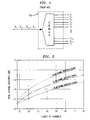
- FIG. 1 shows a typical n -channel optical demultiplexer unit 100 that receives a composite multi-wavelength optical signal and separates the composite signal into individual optical channels of different wavelengths, e.g., ⁇ 1 , ⁇ 2 ,... ⁇ n-1 , ⁇ n .
- optical demultiplexers in the prior art such as waveguide grating routers, are not well-suited for wide band DWDM systems having a high number of closely-spaced channels.
- total crosstalk is shown as a function of the number of channels in a WDM system.
- FIG. 2 illustrates how crosstalk will typically have a greater impact on DWDM systems having high channel counts, such as 80-channel systems, for example.
- FIG. 2 represents the ideal case of no spectral power divergence which will be described in more detail below.
- FIG. 2 shows three exemplary curves of total system crosstalk as a function of the number of channels, wherein each curve is associated with a demultiplexer having a different channel crosstalk level design, e.g., -30 dB, 32 dB, and -34 dB. As shown, the total system crosstalk increases as the number of channels increases.
- total system crosstalk degrades more rapidly with a lower demultiplexer channel crosstalk level, as evidenced by the fact that the separation between the three curves becomes larger as the number of channels increases. This effect is attributable to the increased contribution of crosstalk from non-adjacent channels.
- FIG. 3A shows one illustrative embodiment of a demultiplexer module and associated bandpass post-filter modules according to the principles of the invention. More specifically, demultiplexer and filter portion 300 includes a demultiplexer module 310 and a plurality of bandpass post-filters 320, wherein one bandpass post-filter is coupled to each of the output ports of demultiplexer module 310.
- demultiplexer module 310 receives a composite multi-wavelength optical signal as input and demultiplexes the composite signal into its constituent optical channels, wherein each optical channel is associated with a particular wavelength, e.g., ⁇ 1 , ⁇ 2 ,... ⁇ n-1 , ⁇ n .
- Various types of optical demultiplexers and the operation thereof are well-known to those skilled in the art and are contemplated for use with the present invention.
- a waveguide grating router described in U.S. Patent No. 5,002,350 issued to Dragone on March 26, 1991, which is herein incorporated by reference, may be used in one exemplary embodiment of the invention.
- Demultiplexer module 310 supplies the individual optical channels to corresponding bandpass post-filters 320.
- bandpass post-filter 320 could be a thin-film filter, transmission grating filter, and so on.
- bandpass post-filters 320 are coupled to each output port of demultiplexer module 310 to reduce the total crosstalk contributed from the adjacent and non-adjacent channels and to eliminate interference caused by the free spectral range periodicity associated with demultiplexer module 310.
- FIG. 3B shows another illustrative embodiment of the demultiplexer and filter modules according to the principles of the invention. More specifically, demultiplexer and filter portion 350 includes demultiplexer module 310 and a plurality of bandpass post-filters 320, wherein each bandpass post-filter 320 is coupled to three output ports of demultiplexer module 310 for receiving and filtering the three corresponding optical channels. All other aspects of demultiplexer and filter portion 350 are similar to those previously described for demultiplexer and filter portion 310 (FIG. 3A).
- bandpass post-filters 320 may be designed to filter less than three or more than three optical channels.
- bandpass post-filters 320 that filter more than one optical channel of a particular wavelength
- the optical demultiplexer arrangement according to the principles of the invention can be appropriately designed for cost or other performance considerations. For example, while optimum crosstalk suppression may be achieved when each bandpass post-filter covers only one output port of a demultiplexer module, a large number of bandpass post-filters would be required for this embodiment.
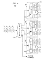
- FIG. 4 shows an illustrative embodiment of the scalable optical demultiplexer arrangement according to the principles of the invention.
- optical demultiplexer arrangement 400 includes an optical router device 375 for distributing the wavelength division multiplexed optical signal among a plurality of output ports.
- optical router device 375 receives the multi-wavelength signals having optical channels of particular wavelengths, represented here as wavelengths ⁇ 1 , ⁇ 2 ,... ⁇ n-1 , ⁇ n , wavelengths ⁇ ' 1 , ⁇ ' 2 ,... ⁇ ' n-1 , ⁇ ' n and wavelengths ⁇ " 1 , ⁇ " 2 ,... ⁇ " n-1 , ⁇ " n .
- Optical router 375 includes M output ports coupled to corresponding demultiplexer and filter portions 350-352. More specifically, the output ports of optical router 375 are coupled to demultiplexer modules 310-312. Demultiplexer modules 310-312 include a plurality of output ports which are coupled to corresponding bandpass post-filters 330-332.
- demultiplexer modules 310-312 separate the composite signals into constituent optical channels each having a particular wavelength.
- demultiplexer 310 separates optical channels corresponding to wavelengths ⁇ 1 , ⁇ 2 ,... ⁇ n-1 , ⁇ n
- demultiplexer 311 separates optical channels corresponding to wavelengths ⁇ ' 1 , ⁇ ' 2 ,... ⁇ ' n-1 , ⁇ ' n
- demultiplexer 312 separates optical channels corresponding to wavelengths ⁇ " 1 , ⁇ " 2 ,... ⁇ " n-1 , ⁇ " n .
- Bandpass post-filters 330-332 are configured as previously described in FIG.
- each post-filter 330-332 is coupled to a plurality of output ports at demultiplexers 310-312.
- post-filters 330 associated with demultiplexer 310 are coupled to three output ports of demultiplexer 310 for receiving and filtering three demultiplexed optical channels supplied by demultiplexer 310.
- Post-filters 331-332 operate in a similar manner.
- optical channels having wavelengths ⁇ 1 , ⁇ 2 ,... ⁇ n-1 , ⁇ n are supplied as output from filters 330, optical channels having wavelengths ⁇ ' 1 , ⁇ ' 2 ,... ⁇ ' n-1 , ⁇ ' n are supplied as output from filters 331, and optical channels having wavelengths ⁇ " 1 , ⁇ " 2 ,... ⁇ " n-1 , ⁇ " n are supplied as output from filters 332.
- optical router device 375 could be an M -port power splitter or an M -port WDM band filter, where M corresponds to the total number of output ports for coupling to demultiplexer modules 350-352 and demultiplexer modules (not shown) that may be added later as part of a system upgrade.
- M corresponds to the total number of output ports for coupling to demultiplexer modules 350-352 and demultiplexer modules (not shown) that may be added later as part of a system upgrade.
- the bandpass post-filters can provide the necessary "wavelength clean-up", i.e., filtering out unwanted wavelengths, which will be described in more detail below.
- guard bands are not required when using an M -port splitter and, as a result, a continuous wide wavelength band can be achieved.
- guard bands will be required based on the bandpass filter technology. Consequently, the wide wavelength band is discontinuous.
- FIG. 4 illustrates an important aspect of the invention, that being the modularity and scalability of optical demultiplexer arrangement 400.
- optical demultiplexer arrangement 400 accommodates future system upgrades, e.g., the addition of demultiplexer modules and post-filters to accommodate additional optical channels, without the need for redesign or disruption in existing service. Because the total number of channels of the DWDM system is partitioned into several demultiplexer modules and then post-filtered, the low crosstalk levels achieved in the optical demultiplexer arrangement according to the principles of the invention are independent of system growth.
- each demultiplexer module will have a smaller free spectral range to cover a subset of the total number of channels as compared with the large free spectral range if the demultiplexing function was not partitioned.
- optical demultiplexer arrangement is also significant in that individual components, e.g., individual demultiplexer modules, post-filter packs. etc., can be physically smaller and less costly than would be the case in a single optical demultiplexer device.
- demultiplexing 80 channels in a single optical demultiplexer would require a large device size that is not feasible given current fabrication technologies, such as silicon optical bench (i.e., silica-on-silicon).
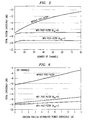
- FIG. 5 shows three exemplary curves of total system crosstalk as a function of the number of channels in accordance with the principles of the invention. Two of the curves reflect the reduction of total system crosstalk that could be achieved with an optical demultiplexer arrangement that incorporates bandpass post-filters. The remaining curve shows total system crosstalk for an embodiment without bandpass post-filters is provided for comparison purposes.
- N ch denotes the number of demultiplexer ports coupled to the bandpass post-filters and, consequently, the number of wavelength channels to be filtered by each bandpass post-filter.
- filter bandwidth BW f the selection of filter bandwidth, BW f , for the bandpass post-filters is based on the number of optical channels to be filtered by the bandpass post-filter as well as the bandpass filter technology selected for implementation.
- filter bandwidth BW f should be in the range ⁇ f ⁇ BW f ⁇ N ch ⁇ ⁇ f , where ⁇ f denotes the channel spacing between optical channels in the DWDM system and N ch denotes the number of optical channels supplied to the bandpass post-filter.
- FIG. 5 also illustrates another important aspect of the optical demultiplexer arrangement according to the principles of the invention.
- FIG. 5 illustrates that total system crosstalk is substantially independent from channel number growth, i.e., increasing the number of channels in the DWDM system.
- the curve representing no filtering total system crosstalk is similar to that shown in FIG. 2.
- the total system crosstalk achieved with post-filtering according to the principles of the invention is maintained at a relatively constant level.
- This feature is attributable to the fact that total system crosstalk is dominated by a smaller number of channels, e.g., only those within the passband of the post-filters, as a result of the partitioning and subsequent post-filtering according to the principles of the invention. Accordingly, this feature allows for system growth without requiring redesign of the optical demultiplexer arrangement and without discarding existing equipment or disrupting existing service.
- FIG. 6 illustrates the effect of power divergence among optical channels on the total system crosstalk levels.
- the preceding discussion assumed no power divergence or a relatively fixed power divergence profile that can be compensated by well-known techniques known to those skilled in the art, such as with gain flattening filters and in-line optical variable attenuators.
- crosstalk levels are sensitive to the power divergence among the channels.
- channel power divergence can be caused by several factors, such as amplifier gain flatness, scattering losses, fiber losses, and the like, all of which may not be compensated completely.
- the effect of power divergence on crosstalk levels depends on the amplitude and shape of the channel power divergence.
- the effect of power divergence can be more problematic for DWDM systems having a high channel count. As such, existing optical demultiplexers are not optimally designed with this consideration in mind.
- FIG. 6 shows the total system crosstalk as a function of the uniform random distributed power divergence in an 80-channel DWDM system according to the principles of the invention.
- the plot corresponding to no filtering shows higher crosstalk levels as the power divergence increases.
- post-filtering according to the principles of the invention achieves much lower crosstalk levels which are less sensitive to increased power divergence among the channels, especially where a random power divergence profile exists.
- this feature of the invention is attributable to the partitioning and subsequent post-filtering of a smaller number of channels, e.g., only those within the passband of the post-filters, according to the principles of the invention.
- the optical demultiplexer arrangement can substantially eliminate interference caused by the free spectral range periodicity associated with demultiplexer modules, such as waveguide grating routers.
- demultiplexer modules such as waveguide grating routers.
- the free spectral range periodicity associated with each of the separate demultiplexer modules becomes a consideration.
- the periodicity can create interference at the output ports of the demultiplexer modules, e.g., output ports may include the desired wavelength channel as well as the wavelength channels separated by an integral number of free spectral ranges from the desired wavelength channel.
- partitioning the total number of channels into smaller groups of channels allows for demultiplexers 310-311 to be implemented with smaller device sizes and smaller free spectral ranges.
- the smaller free spectral ranges of the demultiplexers results in wavelengths outside of the free spectral range (e.g., ⁇ i ⁇ m FSR, where m is an integer and m ⁇ 0) being routed to the same output ports of demultiplexers 310 and 311.
- wavelengths at the other grating orders would exit from the same output ports of each demultiplexer.
- the first output port of demultiplexer 310 would have ⁇ 1 , ⁇ 1 ⁇ FSR, ⁇ 1 ⁇ 2 FSR, and so on.
- post-filters 320 and 321 effectively eliminate this type of interference by filtering out the unwanted wavelengths.
- post-filter 320 associated with the first output port of demultiplexer 310 filters out ⁇ 1 ⁇ FSR, ⁇ 1 ⁇ 2 FSR, and so on, so that only ⁇ 1 remains.
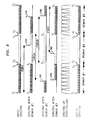
- FIG. 8 is a simplified representation of how post-filtering according to the principles of the invention can filter wavelengths outside of the free spectral range of the demultiplexer.
- the "spectra after DEMUX#1" shows how wavelengths beyond the free spectral range of DEMUX#1 may interfere with channels within the free spectral range of DEMUX#1.
- Free spectral range FSR1 is shown to extend beyond the input wavelength band for DEMUX#1 because of the fact that only a portion of the free spectral range represents usable bandwidth.
- the post-filters corresponding to DEMUX#1 are designed to filter wavelengths that are outside of the usable bandwidth of DEMUX#1.
- the "output spectra of DEMUX#1" only includes those desired wavelengths from the input spectra of DEMUX#1.
- the same principles apply to DEMUX#2 and DEMUX#3.
- FSR2A and FSR2B are only meant to illustrate two possible design choices for the free spectral range of DEMUX#2.
- Post-filtering also provides "spectral purification" with regard to other unwanted wavelengths, e.g., other than those described above.
- the supervisory wavelength channel e.g., 1510 nm in ITU
- the other optical channels to a respective demultiplexer can be filtered out by the post-filters provided the wavelength is not within the passband of the post-filter.
- wavelength alignment can be easily achieved and can tolerate temperature variations without the need for temperature control.
- the optical demultiplexer arrangement provides a modular and highly scalable solution for DWDM systems that reduces the total system crosstalk, substantially eliminates interference caused by free spectral range periodicity associated with waveguide grating router demultiplexers, and uses a smaller device footprint which can be implemented with current technologies.
- optical demultiplexer arrangement according to the principles of the invention may be implemented using various types of optical demultiplexers as the demultiplexer modules and various types of filter technologies for the bandpass post-filters.
- the optical demultiplexer arrangement can be used in bi-directional point-to-point DWDM systems as well as add/drop applications. Accordingly, the scope of the invention is limited only by the claims that follow.
Landscapes
- Engineering & Computer Science (AREA)
- Computer Networks & Wireless Communication (AREA)
- Signal Processing (AREA)
- Optical Communication System (AREA)
- Optical Integrated Circuits (AREA)
Applications Claiming Priority (2)
| Application Number | Priority Date | Filing Date | Title |
|---|---|---|---|
| US143878 | 1988-01-14 | ||
| US09/143,878 US6782203B2 (en) | 1998-08-31 | 1998-08-31 | Scalable optical demultiplexing arrangement for wide band dense wavelength division multiplexed systems |
Publications (1)
| Publication Number | Publication Date |
|---|---|
| EP0984580A2 true EP0984580A2 (de) | 2000-03-08 |
Family
ID=22506070
Family Applications (1)
| Application Number | Title | Priority Date | Filing Date |
|---|---|---|---|
| EP99306644A Withdrawn EP0984580A2 (de) | 1998-08-31 | 1999-08-23 | Skalierbare optische Demultiplexing-Vorrichtung für breitbandige dichte Wellenlängenmultiplexsysteme |
Country Status (5)
| Country | Link |
|---|---|
| US (1) | US6782203B2 (de) |
| EP (1) | EP0984580A2 (de) |
| JP (1) | JP2000115134A (de) |
| CN (1) | CN1246627A (de) |
| CA (1) | CA2278817A1 (de) |
Cited By (5)
| Publication number | Priority date | Publication date | Assignee | Title |
|---|---|---|---|---|
| EP1372273A1 (de) * | 2002-06-12 | 2003-12-17 | Agilent Technologies, Inc. - a Delaware corporation - | Übersprechungsbestimmungsgerät |
| EP1241819A3 (de) * | 2001-03-12 | 2004-09-08 | Nippon Sheet Glass Co.,Ltd. | Optische Übertragungs-Überwachungsystem |
| EP1634399A1 (de) * | 2003-06-10 | 2006-03-15 | Nortel Networks Limited | Flexibler, bandiger multiplexer/demultiplexer für wdm-systeme |
| US8744262B2 (en) | 2009-12-08 | 2014-06-03 | Vello Systems, Inc. | Optical subchannel routing, protection switching and security |
| WO2017211413A1 (en) * | 2016-06-08 | 2017-12-14 | Fraunhofer-Gesellschaft zur Förderung der angewandten Forschung e.V. | Optical communication system and method |
Families Citing this family (24)
| Publication number | Priority date | Publication date | Assignee | Title |
|---|---|---|---|---|
| US6721508B1 (en) | 1998-12-14 | 2004-04-13 | Tellabs Operations Inc. | Optical line terminal arrangement, apparatus and methods |
| US6452546B1 (en) * | 2000-06-14 | 2002-09-17 | Hrl Laboratories, Llc | Wavelength division multiplexing methods and apparatus for constructing photonic beamforming networks |
| US7167650B2 (en) * | 2000-06-26 | 2007-01-23 | Jds Uniphase Inc. | Method and apparatus for demultiplexing high bit rate optical signals on dense wavelength grid |
| EP1220483A4 (de) * | 2000-07-31 | 2005-09-07 | Mitsubishi Electric Corp | Vorrichtung zum optischen wellenlängen multiplex |
| US6912340B2 (en) * | 2001-04-23 | 2005-06-28 | Tropic Networks Inc | Optical ring interconnect |
| US6754413B2 (en) * | 2001-04-23 | 2004-06-22 | Tropic Networks Inc. | Optical multiplexer, demultiplexer and methods |
| US7146101B2 (en) * | 2001-11-08 | 2006-12-05 | Altera Corporation | Optical media management channel |
| US7340175B2 (en) | 2002-01-18 | 2008-03-04 | Nec Corporation | Non-uniform optical waveband aggregator and deaggregator and hierarchical hybrid optical cross-connect system |
| US8086101B2 (en) * | 2002-03-08 | 2011-12-27 | Altera Corporation | Multi-city DWDM wavelength link architectures and methods for upgrading |
| JP3985571B2 (ja) * | 2002-04-08 | 2007-10-03 | 住友電気工業株式会社 | 光分波器および光伝送システム |
| US20030232595A1 (en) * | 2002-04-17 | 2003-12-18 | Baker Michael R. | Wireless repeater apparatus, system, and method |
| US7020402B2 (en) * | 2002-06-24 | 2006-03-28 | Scintera Networks, Inc. | Crosstalk compensation engine for reducing signal crosstalk effects within a data signal |
| CN100342441C (zh) * | 2003-06-25 | 2007-10-10 | 建兴电子科技股份有限公司 | 薄型光盘机托盘锁固机构以及光盘片读取写入装置 |
| US7057716B2 (en) | 2003-10-28 | 2006-06-06 | Hrl Laboratories, Llc | White cell antenna beamformers |
| US7302179B2 (en) * | 2003-11-17 | 2007-11-27 | Novx Systems, Inc. | Optical performance monitor using co-located switchable fiber bragg grating array |
| US20090047019A1 (en) * | 2007-08-13 | 2009-02-19 | Paparao Palacharla | Method and System for Communicating Optical Traffic |
| KR100965941B1 (ko) * | 2007-10-05 | 2010-06-24 | 한국과학기술원 | 수동형 광 가입자 망에서 향상된 서비스를 제공하기 위한원격 노드의 구조 및 이를 구비한 수동형 광 가입자 망 |
| SG186353A1 (en) | 2010-07-01 | 2013-01-30 | Newport Corp | Optical demultiplexing system |
| EP2781040B1 (de) * | 2012-02-07 | 2019-10-02 | AFL Telecommunications LLC | Optische anordnungen mit mehrfacher wellenlänge zur inline-messung der optischen leistung von glasfasernetzwerken |
| JP5966616B2 (ja) * | 2012-05-25 | 2016-08-10 | 富士通株式会社 | 波長合分波器及び光受信器 |
| US20160164625A1 (en) * | 2013-07-16 | 2016-06-09 | Commscope Technologies Llc | Distributed wave division multiplexing systems |
| EP3298453A4 (de) * | 2015-05-19 | 2019-01-23 | Newport Corporation | Optisches analysesystem mit lichtverteilung über optische leitung |
| CN108333689B (zh) * | 2018-03-26 | 2024-09-20 | 杭州芯耘光电科技有限公司 | 一种集成可调窄带滤波器的多信道光接收组件 |
| CN113311543A (zh) * | 2021-06-03 | 2021-08-27 | 四川天邑康和通信股份有限公司 | 新型粗波分复用器组件 |
Family Cites Families (11)
| Publication number | Priority date | Publication date | Assignee | Title |
|---|---|---|---|---|
| US5493625A (en) * | 1993-11-16 | 1996-02-20 | At&T Corp. | Fast tunable channel dropping filter |
| IT1272846B (it) * | 1994-11-25 | 1997-06-30 | Pirelli Cavi Spa | "sistema e metodo di telecomunicazione a multiplazione di lunghezza d'onda, con separazione controllata dei canali in uscita e per la determinazione del rapporto segnale/rumore ottico" |
| JPH08278523A (ja) * | 1995-04-05 | 1996-10-22 | Hitachi Ltd | 光増幅装置 |
| US5680490A (en) * | 1995-09-08 | 1997-10-21 | Lucent Technologies Inc. | Comb splitting system and method for a multichannel optical fiber communication network |
| US5808763A (en) * | 1995-10-31 | 1998-09-15 | Jds Fitel Inc. | Optical demultiplexor |
| JP2870499B2 (ja) * | 1996-08-02 | 1999-03-17 | 日立電線株式会社 | 光波長合分波器 |
| US5912749A (en) * | 1997-02-11 | 1999-06-15 | Lucent Technologies Inc. | Call admission control in cellular networks |
| US6281997B1 (en) * | 1997-09-11 | 2001-08-28 | Ciena Corporation | Dense WDM optical multiplexer and demultiplexer |
| US6052499A (en) * | 1998-03-09 | 2000-04-18 | Lucent Technologies Inc. | Optical demultiplexer filter system to eliminate cross-talk side-lobes |
| KR100422372B1 (ko) * | 2001-04-04 | 2004-03-10 | 한국전자통신연구원 | 채널 확장된 파장분할 다중기/역다중기 및 이를 이용한 파장 채널 선택기 |
| US6714702B2 (en) * | 2001-04-03 | 2004-03-30 | Nortel Networks Limited | Optical demultiplexing system and method |
-
1998
- 1998-08-31 US US09/143,878 patent/US6782203B2/en not_active Expired - Lifetime
-
1999
- 1999-07-26 CA CA002278817A patent/CA2278817A1/en not_active Abandoned
- 1999-08-23 EP EP99306644A patent/EP0984580A2/de not_active Withdrawn
- 1999-08-25 CN CN99118073.9A patent/CN1246627A/zh active Pending
- 1999-08-31 JP JP11244522A patent/JP2000115134A/ja active Pending
Cited By (11)
| Publication number | Priority date | Publication date | Assignee | Title |
|---|---|---|---|---|
| EP1241819A3 (de) * | 2001-03-12 | 2004-09-08 | Nippon Sheet Glass Co.,Ltd. | Optische Übertragungs-Überwachungsystem |
| EP1372273A1 (de) * | 2002-06-12 | 2003-12-17 | Agilent Technologies, Inc. - a Delaware corporation - | Übersprechungsbestimmungsgerät |
| US7400831B2 (en) | 2002-06-12 | 2008-07-15 | Avago Technologies Fiber Ip Pte Ltd | Method of detecting the presence of cross-talk and apparatus therefor |
| EP1634399A1 (de) * | 2003-06-10 | 2006-03-15 | Nortel Networks Limited | Flexibler, bandiger multiplexer/demultiplexer für wdm-systeme |
| US8744262B2 (en) | 2009-12-08 | 2014-06-03 | Vello Systems, Inc. | Optical subchannel routing, protection switching and security |
| US9054832B2 (en) | 2009-12-08 | 2015-06-09 | Treq Labs, Inc. | Management, monitoring and performance optimization of optical networks |
| US9485050B2 (en) | 2009-12-08 | 2016-11-01 | Treq Labs, Inc. | Subchannel photonic routing, switching and protection with simplified upgrades of WDM optical networks |
| US10630418B2 (en) | 2009-12-08 | 2020-04-21 | Snell Holdings, Llc | Optical subchannel routing, protection switching and security |
| US10972209B2 (en) | 2009-12-08 | 2021-04-06 | Snell Holdings, Llc | Subchannel photonic routing, switching and protection with simplified upgrades of WDM optical networks |
| WO2017211413A1 (en) * | 2016-06-08 | 2017-12-14 | Fraunhofer-Gesellschaft zur Förderung der angewandten Forschung e.V. | Optical communication system and method |
| US10819431B2 (en) | 2016-06-08 | 2020-10-27 | Fraunhofer-Gesellschaft zur Förderung der angewandten Forschung e.V. | Optical communication system and method |
Also Published As
| Publication number | Publication date |
|---|---|
| JP2000115134A (ja) | 2000-04-21 |
| US6782203B2 (en) | 2004-08-24 |
| CN1246627A (zh) | 2000-03-08 |
| CA2278817A1 (en) | 2000-02-29 |
| US20020012144A1 (en) | 2002-01-31 |
Similar Documents
| Publication | Publication Date | Title |
|---|---|---|
| US6782203B2 (en) | Scalable optical demultiplexing arrangement for wide band dense wavelength division multiplexed systems | |
| US20040252996A1 (en) | Flexible banded MUX/DEMUX architecture for WDM systems | |
| US7437074B2 (en) | Wavelength division multiplexing transmission system | |
| EP1271827A1 (de) | Wellenlängenselektive Add/Drop Vorrichtung für optische Nachrichtensysteme | |
| US7995921B2 (en) | Banded semiconductor optical amplifiers and waveblockers | |
| US6348984B1 (en) | Optical add/drop multiplexer | |
| EP1503532B1 (de) | Optisches Netzwerk mit Teilbandsperrung und Bypass | |
| EP1088417B1 (de) | Verfahren und vorrichtung zur abzweigung von optischen kanälen in einem optischen übertragungssystem | |
| US20010024542A1 (en) | Method and device for dropping optical channels in an optical transmission system | |
| US7480459B2 (en) | Wavelength division multiplexing transmission system | |
| US6614567B1 (en) | Apparatus and method for upgrading the capacity of wavelength division multiplexed optical networks | |
| US7181095B1 (en) | Low loss, noise filtering multiplexer/demultiplexer for reconfigurable OADMs | |
| US6243179B1 (en) | Banded add drop device | |
| EP1638232A2 (de) | Optisches Demultiplexverfahren und Multiplexverfahren und diese verwendende, optische Übertragungsvorrichtung | |
| EP1109341A2 (de) | Optischer Wellenlängen-Add/dropmultiplexer für Übertragungsraten mit Dualsignalen | |
| US6678476B1 (en) | WDM with optical interleaving for increased channel capacity | |
| US7805077B2 (en) | Scalable and movable DWDM usage of CWDM networks | |
| EP2161866B1 (de) | System, vorrichtung und verfahren zur aufwertung eines wellenlängen-multiplex-systems niedriger dichte | |
| US6650809B2 (en) | Multiple band optical multiplexer and demultiplexer | |
| US6608948B2 (en) | Periodic arrayed waveguide grating multiplexer/demultiplexer | |
| CA2443409A1 (en) | High spectral efficiency, high performance optical mux and demux architecture | |
| US7587137B2 (en) | System and method for seamless integration of CWDM and DWDM technologies on a fiber optics infrastructure | |
| EP2117148A1 (de) | Multiplexer mit zusätzlicher optischer Filterung | |
| JP2005020449A (ja) | チャネル多重装置、チャネル分離装置、伝送システム及びチャネル数変更装置 | |
| WO2002019588A1 (en) | An optical communication network |
Legal Events
| Date | Code | Title | Description |
|---|---|---|---|
| PUAI | Public reference made under article 153(3) epc to a published international application that has entered the european phase |
Free format text: ORIGINAL CODE: 0009012 |
|
| AK | Designated contracting states |
Kind code of ref document: A2 Designated state(s): AT BE CH CY DE DK ES FI FR GB GR IE IT LI LU MC NL PT SE |
|
| AX | Request for extension of the european patent |
Free format text: AL;LT;LV;MK;RO;SI |
|
| STAA | Information on the status of an ep patent application or granted ep patent |
Free format text: STATUS: THE APPLICATION HAS BEEN WITHDRAWN |
|
| 18W | Application withdrawn |
Withdrawal date: 20020906 |