EP0984307A1 - Dispersionsverschobene Faser mit zentralem Segment mit niedrigem Brechungsindex - Google Patents
Dispersionsverschobene Faser mit zentralem Segment mit niedrigem Brechungsindex Download PDFInfo
- Publication number
- EP0984307A1 EP0984307A1 EP99402049A EP99402049A EP0984307A1 EP 0984307 A1 EP0984307 A1 EP 0984307A1 EP 99402049 A EP99402049 A EP 99402049A EP 99402049 A EP99402049 A EP 99402049A EP 0984307 A1 EP0984307 A1 EP 0984307A1
- Authority
- EP
- European Patent Office
- Prior art keywords
- index
- fiber
- profile
- central
- sheath
- Prior art date
- Legal status (The legal status is an assumption and is not a legal conclusion. Google has not performed a legal analysis and makes no representation as to the accuracy of the status listed.)
- Withdrawn
Links
- 239000000835 fiber Substances 0.000 title claims abstract description 88
- 239000006185 dispersion Substances 0.000 title claims abstract description 18
- 238000005253 cladding Methods 0.000 claims abstract description 11
- 239000013307 optical fiber Substances 0.000 claims abstract description 9
- VYPSYNLAJGMNEJ-UHFFFAOYSA-N Silicium dioxide Chemical compound O=[Si]=O VYPSYNLAJGMNEJ-UHFFFAOYSA-N 0.000 description 16
- 239000002019 doping agent Substances 0.000 description 16
- 238000004519 manufacturing process Methods 0.000 description 8
- 239000000377 silicon dioxide Substances 0.000 description 8
- 230000035945 sensitivity Effects 0.000 description 7
- 230000008020 evaporation Effects 0.000 description 6
- 238000001704 evaporation Methods 0.000 description 6
- 230000005540 biological transmission Effects 0.000 description 5
- 230000007423 decrease Effects 0.000 description 4
- 229910052732 germanium Inorganic materials 0.000 description 3
- GNPVGFCGXDBREM-UHFFFAOYSA-N germanium atom Chemical compound [Ge] GNPVGFCGXDBREM-UHFFFAOYSA-N 0.000 description 3
- 230000000694 effects Effects 0.000 description 2
- 238000000034 method Methods 0.000 description 2
- 238000004804 winding Methods 0.000 description 2
- PXGOKWXKJXAPGV-UHFFFAOYSA-N Fluorine Chemical compound FF PXGOKWXKJXAPGV-UHFFFAOYSA-N 0.000 description 1
- 238000005452 bending Methods 0.000 description 1
- 230000003247 decreasing effect Effects 0.000 description 1
- 230000003028 elevating effect Effects 0.000 description 1
- 238000005516 engineering process Methods 0.000 description 1
- 229910052731 fluorine Inorganic materials 0.000 description 1
- 239000011737 fluorine Substances 0.000 description 1
- 230000003287 optical effect Effects 0.000 description 1
- 230000003071 parasitic effect Effects 0.000 description 1
- 229920002994 synthetic fiber Polymers 0.000 description 1
Images
Classifications
-
- G—PHYSICS
- G02—OPTICS
- G02B—OPTICAL ELEMENTS, SYSTEMS OR APPARATUS
- G02B6/00—Light guides; Structural details of arrangements comprising light guides and other optical elements, e.g. couplings
- G02B6/02—Optical fibres with cladding with or without a coating
- G02B6/028—Optical fibres with cladding with or without a coating with core or cladding having graded refractive index
- G02B6/0281—Graded index region forming part of the central core segment, e.g. alpha profile, triangular, trapezoidal core
-
- G—PHYSICS
- G02—OPTICS
- G02B—OPTICAL ELEMENTS, SYSTEMS OR APPARATUS
- G02B6/00—Light guides; Structural details of arrangements comprising light guides and other optical elements, e.g. couplings
- G02B6/02—Optical fibres with cladding with or without a coating
- G02B6/02214—Optical fibres with cladding with or without a coating tailored to obtain the desired dispersion, e.g. dispersion shifted, dispersion flattened
- G02B6/02219—Characterised by the wavelength dispersion properties in the silica low loss window around 1550 nm, i.e. S, C, L and U bands from 1460-1675 nm
-
- G—PHYSICS
- G02—OPTICS
- G02B—OPTICAL ELEMENTS, SYSTEMS OR APPARATUS
- G02B6/00—Light guides; Structural details of arrangements comprising light guides and other optical elements, e.g. couplings
- G02B6/02—Optical fibres with cladding with or without a coating
- G02B6/028—Optical fibres with cladding with or without a coating with core or cladding having graded refractive index
- G02B6/0286—Combination of graded index in the central core segment and a graded index layer external to the central core segment
-
- G—PHYSICS
- G02—OPTICS
- G02B—OPTICAL ELEMENTS, SYSTEMS OR APPARATUS
- G02B6/00—Light guides; Structural details of arrangements comprising light guides and other optical elements, e.g. couplings
- G02B6/02—Optical fibres with cladding with or without a coating
- G02B6/036—Optical fibres with cladding with or without a coating core or cladding comprising multiple layers
- G02B6/03605—Highest refractive index not on central axis
- G02B6/03611—Highest index adjacent to central axis region, e.g. annular core, coaxial ring, centreline depression affecting waveguiding
-
- G—PHYSICS
- G02—OPTICS
- G02B—OPTICAL ELEMENTS, SYSTEMS OR APPARATUS
- G02B6/00—Light guides; Structural details of arrangements comprising light guides and other optical elements, e.g. couplings
- G02B6/02—Optical fibres with cladding with or without a coating
- G02B6/036—Optical fibres with cladding with or without a coating core or cladding comprising multiple layers
- G02B6/03616—Optical fibres characterised both by the number of different refractive index layers around the central core segment, i.e. around the innermost high index core layer, and their relative refractive index difference
- G02B6/03638—Optical fibres characterised both by the number of different refractive index layers around the central core segment, i.e. around the innermost high index core layer, and their relative refractive index difference having 3 layers only
- G02B6/03644—Optical fibres characterised both by the number of different refractive index layers around the central core segment, i.e. around the innermost high index core layer, and their relative refractive index difference having 3 layers only arranged - + -
-
- G—PHYSICS
- G02—OPTICS
- G02B—OPTICAL ELEMENTS, SYSTEMS OR APPARATUS
- G02B6/00—Light guides; Structural details of arrangements comprising light guides and other optical elements, e.g. couplings
- G02B6/02—Optical fibres with cladding with or without a coating
- G02B6/02214—Optical fibres with cladding with or without a coating tailored to obtain the desired dispersion, e.g. dispersion shifted, dispersion flattened
- G02B6/02219—Characterised by the wavelength dispersion properties in the silica low loss window around 1550 nm, i.e. S, C, L and U bands from 1460-1675 nm
- G02B6/02276—Dispersion shifted fibres, i.e. zero dispersion at 1550 nm
Definitions
- the present invention relates to a single-mode optical fiber with dispersion offset and central hollow.
- the so-called dispersion-shifted fibers are such that at the transmission wavelength at which they are used, which is generally different from the wavelength of 1.3 ⁇ m for which the dispersion of the silica is substantially zero, the chromatic dispersion of the transmitted wave is substantially zero; that is to say that the non-zero chromatic dispersion of the silica is compensated - hence the use of the term shifted by an increase in the difference in index ⁇ n between the core of the fiber and the optical sheath.
- This index difference makes it possible to offset the wavelength for which the chromatic dispersion is zero; it is obtained by the introduction of dopants into the fiber, during the manufacture of the latter, for example by a process of MCVD known per se, and which is not described in more detail here.
- a typical value for the difference in index between the cladding and the core of the fiber is 24.10 -3 ; the increase in the index in silica can be obtained by using germanium as a dopant.
- the terms sheath and core are known to those skilled in the art; conventionally, the part which extends up to a diameter of 125 ⁇ m is called a sheath.
- the heart corresponds to the part where approximately 70% of the light energy propagates.
- These single-mode fibers must also preferably have characteristics which correspond to the requirements of cable manufacturers and system manufacturers: on the one hand, for cable manufacturers, good "cableability", resulting in a bending capacity of the fiber, which implies a small mode diameter; on the other hand, for systems, a low attenuation, which supposes a mode diameter as large as possible, a large effective area, an appropriate value of the wavelength ⁇ 0 of zero dispersion.
- the use of these fibers for wavelength division multiplex transmission systems makes the constraints even more severe.
- index profile is generally qualified in function of the shape of the curve representing the index as a function of the radius of the fiber. This is called an index profile in "step", "trapezoid” or “triangle” to curves representing the variation of the index as a function of the radius which have respective echelon, trapezoid or triangle shapes.
- steps are generally representative of the theoretical or target profile of the fiber, the fiber manufacturing constraints often leading to a substantially profile different.
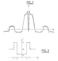
- FR-A-2 724 234 describes a single-mode optical fiber with dispersion offset, with a trapezoid index profile, or in triangle border cases or in a rectangle, with a ring surrounding the trapezoid.
- Figure 1 shows in thin line the appearance of the deposit profile proposed in this document, and in bold line the profile measured on an effectively manufactured fiber.
- the abscissa on the figure 1 give the distance r to the center of the fiber, and the ordinates the index, defined by its difference in percent compared to the index of the sheath of the fiber.
- the index defined by its difference in percent compared to the index of the sheath of the fiber.
- the fiber has a central part, for a radius in modulus less than a value b, having a constant index of a value n 2 less than the index n 3 of the sheath; around this central part, the fiber has an annular part of index n 1 greater than the index n 2 of the central part and the index n 3 of the cladding, for values of the modulus of the radius between b and c .
- the offset of the wavelength of zero chromatic dispersion is mainly linked to the differences in index n 1 -n 3 between the ring and the cladding, and n 1 -n 2 between the ring and the central part of the fiber.
- WO 97/33188 also discloses a single-mode optical fiber with offset dispersion, having a cladding with a given index (n 3 ), and a fiber core with a central part with index (n 2 ) lower than that of the sheath and an external part of index (n 1 ) greater than that of the sheath, the index profile of the fiber being such that the central and external parts of the core are connected together by an inclined flank.
- the central part has a U-shaped profile, that is to say it has a bearing index much lower than that of the sheath.
- the invention provides a dispersion-shifted single-mode optical fiber which allows to keep the characteristics of the coaxial profile fibers known from the point of the wavelength shift for which the chromatic dispersion is zero, but which decreases the manufacturing time of such a fiber and improves its yield while reducing the effects of evaporation of dopants at the center of the fiber. It makes it possible to obtain fibers having a lower attenuation than corresponding fibers of the prior art, and / or a sensitivity to wiring more scaled down.
- the invention proposes a single-mode optical fiber with offset dispersion, having a cladding with a given index (n 3 ), and a fiber core with a central part with index (n 2 ) lower than that of the cladding and an external part of index (n 1 ) greater than that of the sheath, the index profile of said fiber being such that the central and external parts of the core are connected together by an inclined flank, characterized in that the profile of index of the central part of index (n 2 ) is in the shape of "V".
- the amount of dopants in the central part is still decreased, which leads to a further decrease in fiber attenuation optics according to the invention compared to those of the prior art and contributes to facilitating manufacturing the fiber by making it faster and increasing its yield. Indeed, the more the volume of the index part much lower than that of the sheath is the lower, the easier the manufacturing. In addition, the consequences of the evaporation of dopants at the center of the fiber are limited, as explained below.
- the index on the inclined flank is a function proportional to r ⁇ , with r the radius, and the exponent ⁇ a real less than 10.
- the exhibitor is between 0.80 and 1.20.
- the index profile of the external index part (n 1 ) also has a substantially vertical sidewall.
- the amount of dopants in the external part is further reduced, which further leads to a reduction in the attenuation of the fiber obtained.
- the index profile of the external index part (n 1 ) has two inclined sides.
- the fiber may also have a second part of index (n 4 ) greater than that of the sheath, located around said external part, and separated from this by an annular part of lower index (n 5 ).
- this second part preferably has an index profile with at least one inclined side.
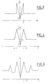
- Figures 3 and 4 show the setpoint index profiles of several modes of embodiment of the invention, for a coaxial profile with a central part of index lower than that of the sheath, and an annular part of index higher than that of the sheath.
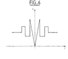
- Figures 5 and 6 show another index profile, for a profile with a central part of index lower than that of the sheath, and two annular parts of index higher than that of the sheath, these two parts having between them a part of lower index.
- FIG. 3 shows a schematic representation of the index profile of a single-mode fiber in a first embodiment of the invention
- the fiber has an index profile in its hollow central part with inclined sides; in other words, the annular part surrounding the hollow central part has a substantially triangular shape, with a flank towards the outside of the fiber that is substantially vertical, and a flank inclined towards the core of the fiber.
- the central part of the fiber, having an index n 2 does not extend, in other words, with the notations of FIG. 2, b is zero.
- ⁇ 1.
- the central part of the fiber has an index profile in "V", and not in "U” as in the prior art.
- the index profile does not have a central plateau, or in terms of surfaces, the surface of the section of the fiber for which the index is n 2 is substantially zero.
- This allows better control of the shape of the profile: as explained above with reference to FIG. 1, the evaporation of the dopant can disturb the real profile of the index at the center of the fiber.
- the presence of a V-shaped profile results in the real fiber by a profile having a more softened shape, close to a U-shape. This avoids large variations in the index, of the type of those of the Figure 1 near the center of the fiber. We avoid parasitic guides in the center of the fiber.
- a fiber according to the invention as shown in FIG. 3, has an attenuation of the same order of magnitude as those according to the publication by SF Mahmoud, and an infinitely better coefficient of sensitivity to curvatures (10 -9 dB / km in the case of the invention; 10 dB / km or 10 -2 dB / km in the prior art).
- FIG. 4 shows a schematic representation of the index profile of a single-mode fiber in a second embodiment of the invention.
- the ring around the central hollow has a triangular shape, with two inclined sides.
- the fibers given by way of example in the embodiments also have an effective surface A eff and a wavelength ⁇ 0 of zero chromatic dispersion compatible with the values conventionally used.
- an effective surface A eff of 95 ⁇ m 2 is obtained, and a wavelength ⁇ 0 of the order of 1430 to 1450 nm.
- FIG. 6 shows an exemplary embodiment of the invention, in the case where the profile has a central part of index less than that of the sheath, and two annular parts of indices n 1 and n 4 greater than that of the sheath , separated by an annular part of lower index n 5 .
- Such a central hollow profile with two rings is described, with index jumps, in EP-A-0 753 771.
- At least one of the index jumps is replaced by an inclined flank.
- the two rings have the same structure as in Figure 4.
- the outer ring is a jump index ring classic, while the ring immediately adjacent to the hollow central part shows the look of Figure 3.
- the fiber has an index profile which on the inclined side (s) is proportional to r ⁇ , with r the radius and ⁇ a real number.
- This number is advantageously close to 1, typically between 0.80 and 1.20. It can also take larger values, and values of the order of 2 remain satisfactory.
- ⁇ remains strictly less than 10.
- the index profile is a polynomial of radius r, preferably a polynomial of degree less than 10.
- the index is a sum of functions of the type r ⁇ i , with ⁇ i less than 10.
- the invention makes it possible to reduce the content of dopant in the fiber, and in particular decrease germanium concentrations to raise the index. We can so improve attenuation, while maintaining a high index jump, and good wavelength shift characteristics for which the dispersion chromatic is zero.
Landscapes
- Physics & Mathematics (AREA)
- General Physics & Mathematics (AREA)
- Optics & Photonics (AREA)
- Chemical & Material Sciences (AREA)
- Dispersion Chemistry (AREA)
- Optical Fibers, Optical Fiber Cores, And Optical Fiber Bundles (AREA)
- Lasers (AREA)
Applications Claiming Priority (2)
| Application Number | Priority Date | Filing Date | Title |
|---|---|---|---|
| FR9810383A FR2782390A1 (fr) | 1998-08-13 | 1998-08-13 | Fibre optique monomode a dispersion decalee et a creux central |
| FR9810383 | 1998-08-13 |
Publications (1)
| Publication Number | Publication Date |
|---|---|
| EP0984307A1 true EP0984307A1 (de) | 2000-03-08 |
Family
ID=9529661
Family Applications (1)
| Application Number | Title | Priority Date | Filing Date |
|---|---|---|---|
| EP99402049A Withdrawn EP0984307A1 (de) | 1998-08-13 | 1999-08-12 | Dispersionsverschobene Faser mit zentralem Segment mit niedrigem Brechungsindex |
Country Status (5)
| Country | Link |
|---|---|
| EP (1) | EP0984307A1 (de) |
| JP (1) | JP2002522811A (de) |
| CN (1) | CN1277678A (de) |
| FR (1) | FR2782390A1 (de) |
| WO (1) | WO2000010041A1 (de) |
Families Citing this family (4)
| Publication number | Priority date | Publication date | Assignee | Title |
|---|---|---|---|---|
| CN105278033B (zh) * | 2015-11-10 | 2019-04-16 | 江苏法尔胜光电科技有限公司 | 一种折射率负渐变型大芯径传能石英光纤 |
| CN105548078A (zh) * | 2016-01-13 | 2016-05-04 | 中国计量学院 | 一种基于侧边抛磨渐变折射率光纤的氢气传感装置 |
| CN106707408A (zh) * | 2017-03-28 | 2017-05-24 | 中山大学 | 一种基于环形结构纤芯的折射率渐变型光纤 |
| CN112099130B (zh) * | 2020-09-25 | 2021-07-13 | 东北大学 | 一种低芯间串扰的斜坡型折射率分布多芯光纤 |
Citations (4)
| Publication number | Priority date | Publication date | Assignee | Title |
|---|---|---|---|---|
| FR2724234A1 (fr) * | 1994-09-05 | 1996-03-08 | Alcatel Fibres Optiques | Fibre optique monomode a dispersion decalee |
| EP0753771A2 (de) * | 1995-07-07 | 1997-01-15 | Alcatel Submarcom | Monomodaler dispersionsverschobener optischer Wellenleiter mit grosser effektiver Modenfläche |
| EP0779524A2 (de) * | 1995-12-15 | 1997-06-18 | Corning Incorporated | Monomode-Lichtwellenleiter mit grosser effektiver Querschnittsfläche |
| WO1997033188A2 (en) * | 1996-02-23 | 1997-09-12 | Corning Incorporated | Large effective area single mode optical waveguide |
-
1998
- 1998-08-13 FR FR9810383A patent/FR2782390A1/fr active Pending
-
1999
- 1999-08-12 WO PCT/FR1999/001974 patent/WO2000010041A1/fr not_active Ceased
- 1999-08-12 JP JP2000565425A patent/JP2002522811A/ja not_active Withdrawn
- 1999-08-12 EP EP99402049A patent/EP0984307A1/de not_active Withdrawn
- 1999-08-12 CN CN 99801594 patent/CN1277678A/zh active Pending
Patent Citations (4)
| Publication number | Priority date | Publication date | Assignee | Title |
|---|---|---|---|---|
| FR2724234A1 (fr) * | 1994-09-05 | 1996-03-08 | Alcatel Fibres Optiques | Fibre optique monomode a dispersion decalee |
| EP0753771A2 (de) * | 1995-07-07 | 1997-01-15 | Alcatel Submarcom | Monomodaler dispersionsverschobener optischer Wellenleiter mit grosser effektiver Modenfläche |
| EP0779524A2 (de) * | 1995-12-15 | 1997-06-18 | Corning Incorporated | Monomode-Lichtwellenleiter mit grosser effektiver Querschnittsfläche |
| WO1997033188A2 (en) * | 1996-02-23 | 1997-09-12 | Corning Incorporated | Large effective area single mode optical waveguide |
Non-Patent Citations (1)
| Title |
|---|
| MAHMOUD S F ET AL: "TRANSMISSION CHARACTERISTICS OF A COAXIAL OPTICAL FIBER LINE", JOURNAL OF LIGHTWAVE TECHNOLOGY, vol. 11, no. 11, 1 November 1993 (1993-11-01), pages 1717 - 1720, XP000416667 * |
Also Published As
| Publication number | Publication date |
|---|---|
| WO2000010041A1 (fr) | 2000-02-24 |
| CN1277678A (zh) | 2000-12-20 |
| FR2782390A1 (fr) | 2000-02-18 |
| JP2002522811A (ja) | 2002-07-23 |
Similar Documents
| Publication | Publication Date | Title |
|---|---|---|
| EP1067412B1 (de) | Dispersionkompensierende optische Faser | |
| EP1030199B1 (de) | Optische Faser für Wellenlängenmultiplex-Übertragungssysteme | |
| EP0984308A1 (de) | Dispersionsverschobene optische Einmodenfaser mit einem äusseren Brechzahl-Ring | |
| FR2914751A1 (fr) | Fibre optique monomode | |
| FR2941540A1 (fr) | Fibre optique monomode presentant une surface effective elargie | |
| FR2941541A1 (fr) | Fibre optique monomode | |
| FR2512215A1 (fr) | Fibre optique a double gaine | |
| EP1046069A1 (de) | Optischer faser mit optimalem verhältnis zwischen effektiven flächen und dispersionsgradienten für faseroptische wellenlängemultiplexübertragungssystemen | |
| EP0992817B1 (de) | Dispersionsverschobene monomodige optische Faser mit grosser effektiver fläche | |
| EP0987568B1 (de) | Optimierte dispersionsverschobene monomodige optische Faser für hohe Datenraten | |
| EP1004905B1 (de) | Dispersionskompensierende Faser für ein faseroptisches Wellenlängenmultiplexübertragungssystem mit eine Dispersionsverschobene Faserstrecke | |
| EP1081514A1 (de) | Optische Faser zur Kompensation der chromatischen Dispersion einer optischen Faser mit positiver chromatischer Dispersion | |
| EP0992818B1 (de) | Dispersionsverschobene optische Faser mit positiver Dispersion bei 1550 nm | |
| EP1256554B1 (de) | Optische Stufenindexfaser mit dotiertem Kern und Mantel, Vorform und Herstellungsverfahren fÜr eine solche Faser | |
| EP1018656B1 (de) | Optische Faser mit geringem Gradienten der chromatischen Dispersion | |
| EP0984307A1 (de) | Dispersionsverschobene Faser mit zentralem Segment mit niedrigem Brechungsindex | |
| EP1030200B1 (de) | Optische Faser mit grosser effektiver Fläche und starker chromatischer Dispersion | |
| FR2790106A1 (fr) | Fibre optique a saut d'indice a large bande | |
| EP1018812B1 (de) | Faseroptisches WDM Übertragungssystem mit Farbzerstreuungskompensation | |
| FR2782392A1 (fr) | Fibre optique monomode a dispersion decalee comprenant un anneau exterieur |
Legal Events
| Date | Code | Title | Description |
|---|---|---|---|
| PUAI | Public reference made under article 153(3) epc to a published international application that has entered the european phase |
Free format text: ORIGINAL CODE: 0009012 |
|
| AK | Designated contracting states |
Kind code of ref document: A1 Designated state(s): AT BE CH CY DE DK ES FI FR GB GR IE IT LI LU MC NL PT SE |
|
| AX | Request for extension of the european patent |
Free format text: AL;LT;LV;MK;RO;SI |
|
| 17P | Request for examination filed |
Effective date: 20000908 |
|
| AKX | Designation fees paid |
Free format text: AT BE CH CY DE DK ES FI FR GB GR IE IT LI LU MC NL PT SE |
|
| STAA | Information on the status of an ep patent application or granted ep patent |
Free format text: STATUS: THE APPLICATION IS DEEMED TO BE WITHDRAWN |
|
| 18D | Application deemed to be withdrawn |
Effective date: 20030301 |