EP0984300B1 - Parking-aid device for a motor vehicle - Google Patents
Parking-aid device for a motor vehicle Download PDFInfo
- Publication number
- EP0984300B1 EP0984300B1 EP99115306A EP99115306A EP0984300B1 EP 0984300 B1 EP0984300 B1 EP 0984300B1 EP 99115306 A EP99115306 A EP 99115306A EP 99115306 A EP99115306 A EP 99115306A EP 0984300 B1 EP0984300 B1 EP 0984300B1
- Authority
- EP
- European Patent Office
- Prior art keywords
- sensor
- motor vehicle
- radar
- sensors
- distance
- Prior art date
- Legal status (The legal status is an assumption and is not a legal conclusion. Google has not performed a legal analysis and makes no representation as to the accuracy of the status listed.)
- Expired - Lifetime
Links
Images

Classifications
-
- G—PHYSICS
- G01—MEASURING; TESTING
- G01S—RADIO DIRECTION-FINDING; RADIO NAVIGATION; DETERMINING DISTANCE OR VELOCITY BY USE OF RADIO WAVES; LOCATING OR PRESENCE-DETECTING BY USE OF THE REFLECTION OR RERADIATION OF RADIO WAVES; ANALOGOUS ARRANGEMENTS USING OTHER WAVES
- G01S13/00—Systems using the reflection or reradiation of radio waves, e.g. radar systems; Analogous systems using reflection or reradiation of waves whose nature or wavelength is irrelevant or unspecified
- G01S13/88—Radar or analogous systems specially adapted for specific applications
- G01S13/93—Radar or analogous systems specially adapted for specific applications for anti-collision purposes
- G01S13/931—Radar or analogous systems specially adapted for specific applications for anti-collision purposes of land vehicles
-
- B—PERFORMING OPERATIONS; TRANSPORTING
- B60—VEHICLES IN GENERAL
- B60T—VEHICLE BRAKE CONTROL SYSTEMS OR PARTS THEREOF; BRAKE CONTROL SYSTEMS OR PARTS THEREOF, IN GENERAL; ARRANGEMENT OF BRAKING ELEMENTS ON VEHICLES IN GENERAL; PORTABLE DEVICES FOR PREVENTING UNWANTED MOVEMENT OF VEHICLES; VEHICLE MODIFICATIONS TO FACILITATE COOLING OF BRAKES
- B60T2201/00—Particular use of vehicle brake systems; Special systems using also the brakes; Special software modules within the brake system controller
- B60T2201/10—Automatic or semi-automatic parking aid systems
-
- G—PHYSICS
- G01—MEASURING; TESTING
- G01S—RADIO DIRECTION-FINDING; RADIO NAVIGATION; DETERMINING DISTANCE OR VELOCITY BY USE OF RADIO WAVES; LOCATING OR PRESENCE-DETECTING BY USE OF THE REFLECTION OR RERADIATION OF RADIO WAVES; ANALOGOUS ARRANGEMENTS USING OTHER WAVES
- G01S13/00—Systems using the reflection or reradiation of radio waves, e.g. radar systems; Analogous systems using reflection or reradiation of waves whose nature or wavelength is irrelevant or unspecified
- G01S13/88—Radar or analogous systems specially adapted for specific applications
- G01S13/93—Radar or analogous systems specially adapted for specific applications for anti-collision purposes
- G01S13/931—Radar or analogous systems specially adapted for specific applications for anti-collision purposes of land vehicles
- G01S2013/9314—Parking operations
-
- G—PHYSICS
- G01—MEASURING; TESTING
- G01S—RADIO DIRECTION-FINDING; RADIO NAVIGATION; DETERMINING DISTANCE OR VELOCITY BY USE OF RADIO WAVES; LOCATING OR PRESENCE-DETECTING BY USE OF THE REFLECTION OR RERADIATION OF RADIO WAVES; ANALOGOUS ARRANGEMENTS USING OTHER WAVES
- G01S13/00—Systems using the reflection or reradiation of radio waves, e.g. radar systems; Analogous systems using reflection or reradiation of waves whose nature or wavelength is irrelevant or unspecified
- G01S13/88—Radar or analogous systems specially adapted for specific applications
- G01S13/93—Radar or analogous systems specially adapted for specific applications for anti-collision purposes
- G01S13/931—Radar or analogous systems specially adapted for specific applications for anti-collision purposes of land vehicles
- G01S2013/9324—Alternative operation using ultrasonic waves
-
- G—PHYSICS
- G01—MEASURING; TESTING
- G01S—RADIO DIRECTION-FINDING; RADIO NAVIGATION; DETERMINING DISTANCE OR VELOCITY BY USE OF RADIO WAVES; LOCATING OR PRESENCE-DETECTING BY USE OF THE REFLECTION OR RERADIATION OF RADIO WAVES; ANALOGOUS ARRANGEMENTS USING OTHER WAVES
- G01S13/00—Systems using the reflection or reradiation of radio waves, e.g. radar systems; Analogous systems using reflection or reradiation of waves whose nature or wavelength is irrelevant or unspecified
- G01S13/88—Radar or analogous systems specially adapted for specific applications
- G01S13/93—Radar or analogous systems specially adapted for specific applications for anti-collision purposes
- G01S13/931—Radar or analogous systems specially adapted for specific applications for anti-collision purposes of land vehicles
- G01S2013/9327—Sensor installation details
- G01S2013/93275—Sensor installation details in the bumper area
Definitions
- the invention relates to a parking aid for a motor vehicle, which the distance measures an object to the motor vehicle without contact and several Has sensors which are arranged on the motor vehicle, each Sensor emits a signal and that of one located in the beam direction Object receives reflected signal again, one with the sensors connected evaluation device the distance from the received signals determined between the object and the motor vehicle.
- a generic collision warning device is from the unpublished patent application DE 197 11 467.9 known in which a non-contact distance measurement between an obstacle and a motor vehicle with several Sensors is performed.
- a sensor always sends in Sensor signal from which is in the sensor beam object is reflected. The reflected signal is received by all sensors.
- To imaginary objects To be able to exclude safely, are from the terms three possible positions of the object Motor vehicle determined. Only the positions of the Object recognized as real, which by all three sensors were detected.
- EP 0 707 220 A2 is a radar system for collision avoidance known in a motor vehicle, in which the Scope of the motor vehicle, several radar modules are distributed, which have different detection areas. The The sensor beam of each module is directed in a different direction radiated.
- a compact obstacle detection system with different Antennas are known from EP 0 740 166 A1. Everybody is there A radar sensor is attached to the outside of each bumper. Due to the different antenna configurations different detection areas generated.
- the invention is therefore based on the object of an arrangement for contactless measurement of the distance between one Specify object and a motor vehicle in which the Effort for the electrical synchronization of the sensors is reduced and still reliable detection of the real object for an accurate distance measurement is possible.
- the object is characterized by the features of Claim 1 solved.
- the invention has the advantage that due to the arrangement the sensors at approximately the same location for indirect runtime measurements can be completely dispensed with.
- the elaborate electronic synchronization in terms of run times is therefore not applicable.
- the real object is alone through direct runtime measurements from the sensor to the object and back determined for the same sensor.
- the evaluation device controls all sensors one after the other to send the sensor signal. Every sensor controlled with the same frequency.
- the proposed arrangement provides greater redundancy in the detection areas the single converter can be achieved in the particularly critical close range, which enables a better quality of the calculation of the object distance is.
- the evaluation device determines the transit time between sending the sensor signal from a sensor and receiving the reflected sensor signal by the same sensor and determined from the so determined the running times of the three sensors, the position and the distance of the Motor vehicle to the object.
- a compact device is achieved if the evaluation device has a building unit with a sensor.
- the evaluation unit can also electronics in itself in the motor vehicle.
- the device according to the invention is particularly suitable for radar sensors, where the problems with runtime synchronization are particularly serious are.
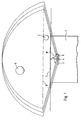
- Figure 1 shows schematically a reversing and parking aid, such as in motor vehicles is being used.
- On the rear bumper 2 of a motor vehicle 1 are three radar sensors 3, 4, 5 at the same height in the immediate vicinity arranged one another, the lateral distance of the radar sensors 3, 4, 5 so is chosen that inaccuracies of the sensor signals are reliably prevented.
- the radar sensors 3, 4, 5 are under the vehicle body Arranged vehicle floor and all have the same distance A to Bumper 2 of motor vehicle 1.
- beam guide channels are not shown provided between the radar sensors 3, 4, 5 and Bumpers 2 run and shield the beam path of the radar sensors 3, 4, 5.
- the opening angle ⁇ of the three radar sensors 3, 4, 5 is approximately the same and is approximately 140 to 170 degrees, which makes up the entire bumper area is also detected with its edge areas. This can be a stationary obstacle 6, 7 up to a distance of more than two meters from the motor vehicle can be detected.
- the rear motor vehicle area becomes complete and reliably detects the presence of obstacles 6, 7.
- An obstacle 7 is located in the area between the bumper 2 and the detection horizon 8.
- the detection horizon 8 extends approximately 50 cm away from the bumper 2 and is used by conventional reversing and parking aids not evaluated. By resetting the radar sensors 3, 4, 5, obstacles in this area are also reliably recognized.
- the radar sensors 3, 4, 5 used serve both as transmitters and as Receiver.
- an evaluation unit 8 which is preferably is a microprocessor, via transmit 9 and receive lines 10 connected to each of the radar sensors 3, 4, 5.
- the microprocessor points an input and output unit 11, a central processing unit 12 and a working memory 13 and a read-only memory 14.
- the evaluation unit 8 is connected to a display device 15 which is usually a speaker and / or an optical device that at Approaching the motor vehicle to an obstacle gives a warning signal.
- the evaluation unit 8 generates control pulses simultaneously for all radar sensors 3, 4, 5, which are forwarded via line 9 to the respective radar sensor 3, 4 and 5 and converted there into corresponding radar signals in the micro-pulse range become.
- Each radar sensor 3, 4, 5 sends a radar beam with a different frequency.
- the radar sensor 3, 4, 5 emitted radar beam reflected by object 6 (or object 7 in FIG. 1), wherein each radar sensor 3, 4, 5 receives its reflected radar signal (echoes).
- all three radar sensors 3, 4, 5 switched to reception by the evaluation unit 8 and the received one Echo converted into an electrical signal, which via line 10 from each radar sensor 3, 4, 5 to the evaluation unit 8.
- the evaluation unit 8 measures using its internal clock, not shown the transit time between sending and receiving the electrical Impulse for each radar sensor 3, 4, 5 and stores them in the working memory 13 from.
Description
Die Erfindung betrifft eine Einparkhilfe für ein Kraftfahrzeug, welche den Abstand eines Objektes zu dem Kraftfahrzeug berührungslos mißt und mehrere Sensoren aufweist, die an dem Kraftfahrzeug angeordnet sind, wobei jeder Sensor ein Signal ausstrahlt und das von einem sich in Strahlrichtung befindlichen Objekt reflektierte Signal wieder empfängt,wobei eine mit den Sensoren verbundene Auswerteeinrichtung aus den empfangenen Signalen den Abstand zwischen Objekt und dem Kraftfahrzeug ermittelt.The invention relates to a parking aid for a motor vehicle, which the distance measures an object to the motor vehicle without contact and several Has sensors which are arranged on the motor vehicle, each Sensor emits a signal and that of one located in the beam direction Object receives reflected signal again, one with the sensors connected evaluation device the distance from the received signals determined between the object and the motor vehicle.
Um das Fahren mit dem Kraftfahrzeug zu erleichtern und Zusammenstöße mit Wagen oder anderen im Weg befindlichen Gegenständen zu verhindern, ist es bekannt, an der Front- und/oder Rückseite des Kraftfahrzeuges Sensoren vorzusehen, welche beispielsweise Ultraschall- oder Radarsignale aussenden und die von dem Hindernis reflektierten Signale wieder zu empfangen. Dabei wird der Abstand zwischen dem am Kraftfahrzeug angeordneten Sensor und dem Hindernis aus der Laufzeit des Signals vom Sensor zum Hindernis und wieder zurückbestimmt. To make driving easier and collisions with It is to prevent trolleys or other objects in the way known to provide sensors on the front and / or rear of the motor vehicle, which emit, for example, ultrasound or radar signals and to receive the signals reflected by the obstacle again. Doing so the distance between the sensor arranged on the motor vehicle and the Obstacle from the running time of the signal from the sensor to the obstacle and again back determined.
Eine gattungsgemäße Kollisionswarneinrichtung ist aus der noch unveröffentlichten Patentanmeldung DE 197 11 467.9 bekannt, bei welcher eine berührungslose Abstandsmessung zwischen einem Hindernis und einem Kraftfahrzeug mit mehreren Sensoren durchgeführt wird. Dabei sendet immer ein Sensor ein Sensorsignal aus, welches von einem sich im Sensorstrahl befindlichen Objekt reflektiert wird. Das reflektierte Signal wird von allen Sensoren empfangen. Um imaginäre Objekte sicher ausschließen zu können, werden aus den Laufzeiten dreier Sensoren alle möglichen Positionen des Objektes zum Kraftfahrzeug bestimmt. Dabei werden nur die Positionen des Objektes als real anerkannt, welche durch alle drei Sensoren detektiert wurden.A generic collision warning device is from the unpublished patent application DE 197 11 467.9 known in which a non-contact distance measurement between an obstacle and a motor vehicle with several Sensors is performed. A sensor always sends in Sensor signal from which is in the sensor beam object is reflected. The reflected signal is received by all sensors. To imaginary objects To be able to exclude safely, are from the terms three possible positions of the object Motor vehicle determined. Only the positions of the Object recognized as real, which by all three sensors were detected.
Gemäß EP 0 707 220 A2 ist ein Radarsystem zur Kollisionsvermeidung an einem Kraftfahrzeug bekannt, bei welchem um den Umfang des Kraftfahrzeuges mehrere Radarmodule verteilt sind, die unterschiedliche Detektionsbereiche aufweisen. Der Sensorstrahl jedes Moduls wird dabei in eine andere Richtung abgestrahlt.According to EP 0 707 220 A2 is a radar system for collision avoidance known in a motor vehicle, in which the Scope of the motor vehicle, several radar modules are distributed, which have different detection areas. The The sensor beam of each module is directed in a different direction radiated.
Ein kompaktes Hinderniserkennungssystem mit verschiedenen Antennen ist aus EP 0 740 166 A1 bekannt. Dabei ist an jeder Außenseite einer Stoßstange je ein Radarsensor befestigt. Aufgrund der verschiedenen Antennenkonfigurationen werden unterschiedliche Detektionsbereiche erzeugt.A compact obstacle detection system with different Antennas are known from EP 0 740 166 A1. Everybody is there A radar sensor is attached to the outside of each bumper. Due to the different antenna configurations different detection areas generated.
Insbesondere für die als indirekt bezeichnete Laufzeitmessung, bei welcher das Signal von einem Sensor ausgesandt und das reflektierte Signal von einem anderen Sensor empfangen wird, ist es notwendig, dass die Sensoren mit Hilfe einer Auswerteeinrichtung synchronisiert werden, so dass jeder Sensor auch empfangsbereit ist, wenn das von dem Hindernis reflektierte Signal ihn erreicht. Dabei steuert die Auswerteeinrichtung die zeitliche Abfolge in dem Sinn, dass ein Sensor ein Signal sendet und anschließend alle Sensoren zeitgleich empfangsbereit geschaltet werden.In particular for the runtime measurement referred to as indirect, where the signal is sent from a sensor and receive the reflected signal from another sensor is, it is necessary that the sensors with the help of a Evaluation device can be synchronized so that everyone Sensor is also ready to receive if that of the obstacle reflected signal reached him. The evaluation device controls this the chronological order in the sense that a Sensor sends a signal and then all sensors be switched ready to receive at the same time.
Insbesondere beim Einsatz von Radarsensoren ist auf Grund der schnellen Signallaufzeiten des ausgesandten und reflektierten Sensorsignales die elektrische Synchronisation der Sensoren sehr aufwendig, wenn nicht gar unmöglich, da die Laufzeiten der Steuersignale auf den Verbindungsleitungen zwischen Auswerteeinrichtung und Sensor immer langsamer sind als die sich annähernd mit Lichtgeschwindigkeit ausbreitenden Sensorsignale.Especially when using radar sensors is due to the fast signal propagation times of the emitted and reflected Sensor signals the electrical synchronization of the sensors very time-consuming, if not impossible, since the terms the control signals on the connecting lines between Evaluation device and sensor are always slower than that sensor signals propagating almost at the speed of light.
Der Erfindung liegt somit die Aufgabe zu Grunde, eine Anordnung zur berührungslosen Messung des Abstandes zwischen einem Objekt und einem Kraftfahrzeug anzugeben, bei welcher der Aufwand für die elektrische Synchronisierung der Sensoren reduziert wird und trotzdem eine zuverlässige Erkennung des realen Objektes für eine genaue Abstandsmessung möglich ist.The invention is therefore based on the object of an arrangement for contactless measurement of the distance between one Specify object and a motor vehicle in which the Effort for the electrical synchronization of the sensors is reduced and still reliable detection of the real object for an accurate distance measurement is possible.
Erfindungsgemäß wird die Aufgabe durch die Merkmale des
Patentanspruchs 1 gelöst.According to the invention, the object is characterized by the features of
Die Erfindung hat den Vorteil, dass aufgrund der Anordnung der Sensoren annähernd an dem selben Ort auf indirekte Laufzeitmessungen vollständig verzichtet werden kann. Die aufwendige elektronische Synchronisation hinsichtlich der Laufzeiten entfällt somit. Das reale Objekt wird allein durch direkte Laufzeitmessungen vom Sensor zum Objekt und zurück zum selben Sensor bestimmt.The invention has the advantage that due to the arrangement the sensors at approximately the same location for indirect runtime measurements can be completely dispensed with. The elaborate electronic synchronization in terms of run times is therefore not applicable. The real object is alone through direct runtime measurements from the sensor to the object and back determined for the same sensor.
Durch das bauliche Zurücksetzen der Sensoren hinter den Stoßfänger werden Messlücken im Nahbereich des Sensors vermieden, da der Messbereich der Sensoren auch im Nahbereich des Stoßfängers voll wirksam ist.By structurally resetting the sensors behind the bumper measurement gaps in the vicinity of the sensor are avoided, because the measuring range of the sensors also in the close range of the bumper is fully effective.
Bei einer Weiterbildung, bei welcher der Aufwand für die Unterscheidung der empfangenen Signale reduziert werden kann, steuert die Auswerteeinrichtung nacheinander alle Sensoren zur Aussendung des Sensorsignales an. Dabei wird jeder Sensor mit derselben Frequenz angesteuert. In a further training, in which the effort for the Distinction of the received signals can be reduced the evaluation device controls all sensors one after the other to send the sensor signal. Every sensor controlled with the same frequency.
Durch die vorgeschlagene Anordnung ist eine größere Redundanz der Erfassungsbereiche der Einzelwandler im besonders kritischen Nahbereich erzielbar, wodurch eine bessere Qualität der Berechnung der Objektentfernung möglich ist.The proposed arrangement provides greater redundancy in the detection areas the single converter can be achieved in the particularly critical close range, which enables a better quality of the calculation of the object distance is.
In einer Ausgestaltung bestimmt die Auswerteeinrichtung die Laufzeit zwischen dem Aussenden des Sensorsignals eines Sensors und dem Empfangen des reflektierten Sensorsignals durch den gleichen Sensor und ermittelt aus den so ermittelten Laufzeiten der drei Sensoren die Position und den Abstand des Kraftfahrzeuges zum Objekt.In one configuration, the evaluation device determines the transit time between sending the sensor signal from a sensor and receiving the reflected sensor signal by the same sensor and determined from the so determined the running times of the three sensors, the position and the distance of the Motor vehicle to the object.
Eine kompakte Einrichtung wird erzielt, wenn die Auswerteeinrichtung eine bauliche Einheit mit einem Sensor bildet. Die Auswerteeinheit kann aber auch eine im Kraftfahrzeug an sich vorhandene Elektronik sein.A compact device is achieved if the evaluation device has a building unit with a sensor. The evaluation unit can also electronics in itself in the motor vehicle.
Die erfindungsgemäße Einrichtung eignet sich besonders für Radarsensoren, bei welchen die Probleme bei der Laufzeitsynchronisation besonders gravierend sind.The device according to the invention is particularly suitable for radar sensors, where the problems with runtime synchronization are particularly serious are.
Die Erfindung läßt zahlreiche Ausführungsbeispiele zu. Eines soll anhand der in der Zeichnung dargestellten Figuren näher erläutert werden.The invention allows numerous exemplary embodiments. One should use the in the figures shown in the drawing are explained in more detail.
Es zeigt
- Figur 1:
- Anordnung zur Bestimmung des Abstandes zwischen einem Hindernis und einem Kraftfahrzeug.
- Figur 2:
- Auswerteeinrichtung
- Figure 1:
- Arrangement for determining the distance between an obstacle and a motor vehicle.
- Figure 2:
- evaluation
Figur 1 zeigt schematisch eine Rückfahr- und Einparkhilfe, wie sie in Kraftfahrzeugen
genutzt wird. An dem rückseitigen Stoßfänger 2 eines Kraftfahrzeuges
1 sind drei Radarsensoren 3, 4, 5 auf gleicher Höhe in unmittelbarer Nähe zu
einander angeordnet, wobei der seitliche Abstand der Radarsensoren 3, 4, 5 so
gewählt wird, daß Ungenauigkeiten der Sensorsignale sicher verhindert werden.
Die Radarsensoren 3, 4, 5 sind dabei unter der Fahrzeugkarosserie am
Fahrzeugboden angeordnet und weisen alle den gleichen Abstand A zum
Stoßfänger 2 des Kraftfahrzeuges 1 auf. Um die Detektion von Fahrzeugbestandteilen
als Hindernis zu verhindern, sind nicht weiter dargestellte Strahlführungskanäle
vorgesehen, die zwischen den Radarsensoren 3, 4, 5 und dem
Stoßfänger 2 verlaufen und den Strahlengang der Radarsensoren 3, 4, 5 abschirmen.Figure 1 shows schematically a reversing and parking aid, such as in motor vehicles
is being used. On the rear bumper 2 of a
Die Öffnungswinkel ϕ der drei Radarsensoren 3, 4, 5 ist annähernd gleich und
beträgt ungefähr 140 bis 170 Grad, wodurch der gesamte Stoßfängerbereich
auch mit seinen Randbereichen erfaßt wird. Damit kann ein stationäres Hindernis
6, 7 bis zu einem Abstand von mehr als zwei Meter zum Kraftfahrzeug
detektiert werden.The opening angle ϕ of the three
Aufgrund dieser Anordnung wird der rückwärtige Kraftfahrzeugbereich vollständig
und zuverlässig auf das Vorhandensein von Hindernissen 6, 7 detektiert.
Ein Hindernis 7 befindet sich dabei in dem Bereich zwischen Stoßfänger 2 und
dem Erkennungshorizont 8. Der Erkennungshorizont 8 erstreckt sich etwa 50
cm entfernt vom Stoßfänger 2 und wird von herkömmlichen Rückfahr- und Einparkhilfen
nicht ausgewertet. Durch das Zurücksetzen der Radarsensoren 3, 4,
5 werden auch Hindernisse in diesem Bereich sicher erkannt.Due to this arrangement, the rear motor vehicle area becomes complete
and reliably detects the presence of
Die verwendeten Radarsensoren 3, 4, 5 dienen sowohl als Sender als auch als
Empfänger. Wie in Figur 2 dargestellt, ist eine Auswerteeinheit 8, welche vorzugsweise
ein Mikroprozessor ist, über Sende- 9 und Empfangsleitungen 10
mit jedem der Radarsensoren 3, 4, 5 verbunden. Der Mikroprozessor weist dabei
eine Ein- und Ausgabeeinheit 11, eine zentrale Recheneinheit 12 sowie
einen Arbeitsspeicher 13 und einen Festwertspeicher 14 auf.The
Die Auswerteeinheit 8 ist mit einer Anzeigeeinrichtung 15 verbunden, welche
üblicherweise ein Lautsprecher und/oder eine optische Einrichtung ist, die bei
Annäherung des Kraftfahrzeuges an ein Hindernis ein Warnsignal abgibt. The
Die Auswerteeinheit 8 erzeugt zeitgleich für alle Radarsensoren 3, 4, 5 Steuerimpulse,
die über die Leitung 9 an den jeweiligen Radarsensor 3, 4 und 5 weitergeleitet
und dort in entsprechende Radarsignale im Mikroimpulsbereich umgewandelt
werden. Jeder Radarsensor 3, 4, 5 sendet dabei einen Radarstrahl
mit einer anderen Frequenz aus. Dabei wird der von jedem Radarsensor 3, 4, 5
ausgesandte Radarstrahl vom Objekt 6 (bzw. Objekt 7 in Figur 1) reflektiert,
wobei jeder Radarsensor 3, 4 , 5 sein reflektiertes Radarsignal (Echos) empfängt.
Nach dem Aussenden der Signale werden alle drei Radarsensoren 3, 4,
5 durch die Auswerteinheit 8 zeitgleich auf Empfang geschaltet und das empfangene
Echo in ein elektrisches Signal umgewandelt, das über die Leitung 10
von jedem Radarsensor 3, 4, 5 an die Auswerteinheit 8 geleitet wird. Die Auswerteeinheit
8 mißt mit Hilfe ihres internen, nicht weiter dargestellten Taktgebers
die Laufzeit zwischen der Ausendung und dem Empfang des elektrischen
Impulses für jeden Radarsensor 3, 4, 5 und speichert diese im Arbeitsspeicher
13 ab.The
Üblicherweise wird aus der Laufzeit t des Ultraschallsignals der Abstand s zwischen
dem Kraftfahrzeug (Sensor) und dem Hindernis annäherungsweise nach
der bekannten Gleichung
Zur genauen Signalauswertung und Abstandsbestimmung wird das an sich bekannten
Auswerteverfahren genutzt, welche beispielsweise aus DE 40 23 538
A1 beschrieben ist. Der nach o.g. Formel bestimmte Abstand eines Sensors
zum Hindernis läßt alle möglichen Positionen des Hindernisses zu, welche auf
einem Kreisbogen angeordnet sind. Die tatsächliche Position des Hindernisses
6, 7 ergibt sich aus dem Schnittpunkt der drei Kreisbögen, wobei jeder Kreisbogen
auf die Messung eines anderen Sensors zurückzuführen ist.This is known per se for precise signal evaluation and distance determination
Evaluation methods used, for example from DE 40 23 538
A1 is described. According to the above Formula determined distance of a sensor
to the obstacle allows all possible positions of the obstacle, which on
are arranged in an arc. The actual position of the
Claims (5)
- Parking aid for a motor vehicle, which measures the distance between an object and the motor vehicle in a contactless manner and has a plurality of radar sensors which are arranged on the motor vehicle, each radar sensor emitting a signal and receiving the signal reflected from an object located in the direction of the beam, an evaluation device connected to the radar sensors determining the distance between the object and the motor vehicle from the signals received, three radar sensors (3, 4, 5) are arranged at a distance from the outer contour (2) of the motor vehicle (1) at approximately the same location, next to one another to provide approximate coverage of the same detection area, the main beam of each radar sensor (3, 4, 5) having approximately the same beam angle (ϕ), with the result that the detection range of each radar sensor (3, 4, 5) covers the entire outer contour extending in the direction of the beam of the radar sensor (3, 4, 5,) and the adjoining space.
- The arrangement as claimed in Claim 1, wherein the evaluation device 8 activates the radar sensors (3, 4, 5) in succession to transmit the sensor signal, all the radar sensors (3, 4, 5) being activated with the same frequency.
- The arrangement as claimed in any of preceding Claims 1 to 3, wherein the evaluation device (8) determines the propagation time between the transmission of the sensor signal of a radar sensor (3, 4, 5) and the reception of the reflected sensor signal by the same radar sensor (3, 4, 5) and from the propagation times of the three radar sensors (3, 4, 5) determined in this way, determines the position and distance of the motor vehicle (1) from the object (6;7).
- The arrangement as claimed in Claim 3, wherein the evaluation device (8) forms a structural unit with one radar sensor (3, 4, 5).
- The arrangement as claimed in Claim 4, wherein the evaluation device (8) is an electronic system that would be present in the vehicle in any case.
Applications Claiming Priority (2)
| Application Number | Priority Date | Filing Date | Title |
|---|---|---|---|
| DE19839942 | 1998-09-02 | ||
| DE19839942A DE19839942C2 (en) | 1998-09-02 | 1998-09-02 | Parking aid for a motor vehicle |
Publications (3)
| Publication Number | Publication Date |
|---|---|
| EP0984300A2 EP0984300A2 (en) | 2000-03-08 |
| EP0984300A3 EP0984300A3 (en) | 2001-08-08 |
| EP0984300B1 true EP0984300B1 (en) | 2003-10-22 |
Family
ID=7879527
Family Applications (1)
| Application Number | Title | Priority Date | Filing Date |
|---|---|---|---|
| EP99115306A Expired - Lifetime EP0984300B1 (en) | 1998-09-02 | 1999-08-03 | Parking-aid device for a motor vehicle |
Country Status (4)
| Country | Link |
|---|---|
| US (1) | US6215415B1 (en) |
| EP (1) | EP0984300B1 (en) |
| KR (1) | KR20000022785A (en) |
| DE (2) | DE19839942C2 (en) |
Families Citing this family (20)
| Publication number | Priority date | Publication date | Assignee | Title |
|---|---|---|---|---|
| US6133826A (en) * | 1999-12-07 | 2000-10-17 | Motorola, Inc. | Method and apparatus for detecting objects |
| JP2002131428A (en) * | 2000-10-25 | 2002-05-09 | Mitsubishi Electric Corp | Ultrasonic obstacle detecting device |
| US6581006B2 (en) * | 2001-01-03 | 2003-06-17 | Delphi Technologies, Inc. | System and method for barrier proximity detection |
| CA2399595A1 (en) * | 2001-08-23 | 2003-02-23 | Kuldip Randhawa | Parking template |
| DE10160299A1 (en) * | 2001-12-07 | 2003-06-18 | Bosch Gmbh Robert | Method and system for detecting at least one object |
| US7124027B1 (en) | 2002-07-11 | 2006-10-17 | Yazaki North America, Inc. | Vehicular collision avoidance system |
| US7102496B1 (en) * | 2002-07-30 | 2006-09-05 | Yazaki North America, Inc. | Multi-sensor integration for a vehicle |
| US6982634B2 (en) * | 2002-11-07 | 2006-01-03 | Shih-Hsiung Li | Method and apparatus for reducing blind spots in obstacle detection |
| DE10252229A1 (en) * | 2002-11-11 | 2004-05-27 | Valeo Schalter Und Sensoren Gmbh | Radar system for monitoring the surroundings of a vehicle, body part with radar system and method therefor |
| DE10258287A1 (en) * | 2002-12-13 | 2004-06-24 | Robert Bosch Gmbh | Motor vehicle object detection system, e.g. for use in an adaptive or automatic cruise control system, comprises an array of three object detection sensors with different sensitivity areas and angles |
| US6992604B2 (en) * | 2003-09-24 | 2006-01-31 | Broadcom Corporation | Method and system for converting digital samples to an analog signal |
| DE102004017890A1 (en) * | 2003-12-17 | 2005-07-21 | Daimlerchrysler Ag | Vehicle with sensor controlled safety system using a combination of near field and far field sensing |
| EP1884421B1 (en) * | 2006-08-04 | 2008-10-08 | Harman Becker Automotive Systems GmbH | Method and system for processing voice commands in a vehicle enviroment |
| DE102008046574A1 (en) * | 2008-09-10 | 2010-03-11 | GM Global Technology Operations, Inc., Detroit | Luggage carrier arrangement for a vehicle rear |
| IT1393868B1 (en) * | 2009-04-01 | 2012-05-11 | Elsag Datamat Spa | PROXIMITY SENSOR FOR PARKING AREA |
| US9007196B2 (en) | 2011-12-14 | 2015-04-14 | Ford Global Technologies, Llc | Cost effective auto-actuation door check |
| DE102012106691A1 (en) * | 2012-07-24 | 2014-01-30 | Valeo Schalter Und Sensoren Gmbh | Alternative installation of a hidden ultrasonic sensor in the motor vehicle |
| DE102013218571A1 (en) * | 2013-09-17 | 2015-03-19 | Volkswagen Aktiengesellschaft | Device and method for lateral environment detection of a motor vehicle |
| CA3097517C (en) * | 2018-04-25 | 2023-04-18 | Waymo Llc | Underbody radar units |
| DE102019219619B4 (en) * | 2019-12-13 | 2023-02-09 | Moba Mobile Automation Ag | DISTANCE MEASUREMENT SYSTEM FOR A VEHICLE |
Family Cites Families (15)
| Publication number | Priority date | Publication date | Assignee | Title |
|---|---|---|---|---|
| JPS5784377A (en) * | 1980-11-14 | 1982-05-26 | Nippon Denso Co Ltd | Device for detecting obstacle |
| US4467313A (en) * | 1980-11-14 | 1984-08-21 | Nippon Soken, Inc. | Automotive rear safety checking apparatus |
| JPS5987597A (en) * | 1982-11-11 | 1984-05-21 | 日産自動車株式会社 | Obstacle detector for vehicle |
| DE3244358C2 (en) * | 1982-12-01 | 1984-10-04 | Daimler-Benz Ag, 7000 Stuttgart | Device for detecting obstacles as a maneuvering aid when parking or turning a motor vehicle |
| DE3420004A1 (en) * | 1984-05-29 | 1985-12-05 | Bosch Gmbh Robert | Separation measurement device for motor vehicles |
| US5008678A (en) * | 1990-03-02 | 1991-04-16 | Hughes Aircraft Company | Electronically scanning vehicle radar sensor |
| DE4023538A1 (en) * | 1990-07-25 | 1992-01-30 | Bosch Gmbh Robert | COLLISION WARNING DEVICE |
| IE71181B1 (en) * | 1991-01-29 | 1997-01-29 | Proximeter Co Ltd | Proximity detector |
| JP3308734B2 (en) * | 1994-10-13 | 2002-07-29 | 本田技研工業株式会社 | Radar module |
| JPH08166448A (en) * | 1994-12-13 | 1996-06-25 | Honda Motor Co Ltd | Peripheral monitor for vehicle |
| US5767793A (en) * | 1995-04-21 | 1998-06-16 | Trw Inc. | Compact vehicle based rear and side obstacle detection system including multiple antennae |
| US5574426A (en) * | 1995-06-30 | 1996-11-12 | Insys, Ltd. | Obstacle detection system for vehicles moving in reverse |
| US5754123A (en) * | 1996-05-06 | 1998-05-19 | Ford Motor Company | Hybrid ultrasonic and radar based backup aid |
| DE19711467C2 (en) * | 1997-03-20 | 2000-12-07 | Mannesmann Vdo Ag | Method for determining the vertical distance between an object and a locally changing device |
| GB2328819A (en) * | 1997-08-30 | 1999-03-03 | Ford Motor Co | Antenna cluster for vehicle collision warning system |
-
1998
- 1998-09-02 DE DE19839942A patent/DE19839942C2/en not_active Expired - Fee Related
-
1999
- 1999-08-03 DE DE59907430T patent/DE59907430D1/en not_active Expired - Fee Related
- 1999-08-03 EP EP99115306A patent/EP0984300B1/en not_active Expired - Lifetime
- 1999-08-30 KR KR1019990036222A patent/KR20000022785A/en not_active Application Discontinuation
- 1999-09-02 US US09/388,760 patent/US6215415B1/en not_active Expired - Fee Related
Also Published As
| Publication number | Publication date |
|---|---|
| DE59907430D1 (en) | 2003-11-27 |
| EP0984300A3 (en) | 2001-08-08 |
| KR20000022785A (en) | 2000-04-25 |
| US6215415B1 (en) | 2001-04-10 |
| DE19839942C2 (en) | 2001-07-12 |
| DE19839942A1 (en) | 2000-03-30 |
| EP0984300A2 (en) | 2000-03-08 |
Similar Documents
| Publication | Publication Date | Title |
|---|---|---|
| EP0984300B1 (en) | Parking-aid device for a motor vehicle | |
| EP0987563B1 (en) | Method for determining the distance separating an object and a movable installation, in particular a motorised vehicle | |
| DE19711467C2 (en) | Method for determining the vertical distance between an object and a locally changing device | |
| DE19744185B4 (en) | Device for distance measurement by means of ultrasound | |
| EP1478547B1 (en) | Method for parking a vehicle | |
| EP1058126B1 (en) | Distance detection device | |
| DE3420004A1 (en) | Separation measurement device for motor vehicles | |
| EP1947476A2 (en) | Method to support the parking procedure of a vehicle | |
| EP0510023B1 (en) | Device for detecting the presence of a vehicle by means of an ultrasonic device | |
| DE4023538A1 (en) | COLLISION WARNING DEVICE | |
| EP0814348B1 (en) | Method for measuring the distance between a vehicle and an object | |
| EP2646846A1 (en) | Driver assistance system for detecting an object in the surroundings of a vehicle | |
| DE102016108756A1 (en) | Radar sensor device for a motor vehicle, driver assistance system, motor vehicle and method for detecting an object | |
| DE19650981A1 (en) | Distance measuring method e.g. for rail vehicles | |
| WO2018219618A1 (en) | Method and apparatus for locating a vehicle for an inductive energy transmission | |
| EP2322952B1 (en) | Method for detecting an object, driver assistance device and vehicle with a driver assistance device | |
| DE112017004938T5 (en) | Detection device, detection method and recording medium | |
| EP3602119B1 (en) | Method for detecting an object in a surrounding area of a motor vehicle with classification of the object, ultrasonic sensor device and motor vehicle | |
| DE102004050794A1 (en) | Environment detection device e.g. for moving motor vehicle, has transmitting device arranged adjacent to first discrete transmitter for radiating ultrasound waves | |
| DE102010051486A1 (en) | Method for ultrasound-based measurement of e.g. front portion of motor car, involves utilizing ultrasound measurement device with transducer device for sending and receiving ultrasonic signal, where running time is considered as signal | |
| DE102017000762A1 (en) | RADAR DEVICE | |
| EP3171196A1 (en) | Method and apparatus for detecting a future approach or a distance between two traffic participants | |
| DE102005060653A1 (en) | Device for detecting an object | |
| DE4218041C2 (en) | Ultrasonic sensor with function monitoring | |
| WO1989007771A1 (en) | Optical tracking instrument |
Legal Events
| Date | Code | Title | Description |
|---|---|---|---|
| PUAI | Public reference made under article 153(3) epc to a published international application that has entered the european phase |
Free format text: ORIGINAL CODE: 0009012 |
|
| AK | Designated contracting states |
Kind code of ref document: A2 Designated state(s): DE FR GB |
|
| AX | Request for extension of the european patent |
Free format text: AL;LT;LV;MK;RO;SI |
|
| PUAL | Search report despatched |
Free format text: ORIGINAL CODE: 0009013 |
|
| AK | Designated contracting states |
Kind code of ref document: A3 Designated state(s): AT BE CH CY DE DK ES FI FR GB GR IE IT LI LU MC NL PT SE |
|
| AX | Request for extension of the european patent |
Free format text: AL;LT;LV;MK;RO;SI |
|
| 17P | Request for examination filed |
Effective date: 20010704 |
|
| RAP1 | Party data changed (applicant data changed or rights of an application transferred) |
Owner name: SIEMENS AKTIENGESELLSCHAFT |
|
| AKX | Designation fees paid |
Free format text: DE FR GB |
|
| 17Q | First examination report despatched |
Effective date: 20020412 |
|
| GRAH | Despatch of communication of intention to grant a patent |
Free format text: ORIGINAL CODE: EPIDOS IGRA |
|
| GRAS | Grant fee paid |
Free format text: ORIGINAL CODE: EPIDOSNIGR3 |
|
| GRAA | (expected) grant |
Free format text: ORIGINAL CODE: 0009210 |
|
| AK | Designated contracting states |
Kind code of ref document: B1 Designated state(s): DE FR GB |
|
| PG25 | Lapsed in a contracting state [announced via postgrant information from national office to epo] |
Ref country code: GB Free format text: LAPSE BECAUSE OF FAILURE TO SUBMIT A TRANSLATION OF THE DESCRIPTION OR TO PAY THE FEE WITHIN THE PRESCRIBED TIME-LIMIT Effective date: 20031022 Ref country code: FR Free format text: LAPSE BECAUSE OF FAILURE TO SUBMIT A TRANSLATION OF THE DESCRIPTION OR TO PAY THE FEE WITHIN THE PRESCRIBED TIME-LIMIT Effective date: 20031022 |
|
| REG | Reference to a national code |
Ref country code: GB Ref legal event code: FG4D Free format text: NOT ENGLISH |
|
| REF | Corresponds to: |
Ref document number: 59907430 Country of ref document: DE Date of ref document: 20031127 Kind code of ref document: P |
|
| GBV | Gb: ep patent (uk) treated as always having been void in accordance with gb section 77(7)/1977 [no translation filed] |
Effective date: 20031022 |
|
| PLBE | No opposition filed within time limit |
Free format text: ORIGINAL CODE: 0009261 |
|
| STAA | Information on the status of an ep patent application or granted ep patent |
Free format text: STATUS: NO OPPOSITION FILED WITHIN TIME LIMIT |
|
| 26N | No opposition filed |
Effective date: 20040723 |
|
| EN | Fr: translation not filed | ||
| PG25 | Lapsed in a contracting state [announced via postgrant information from national office to epo] |
Ref country code: DE Free format text: LAPSE BECAUSE OF NON-PAYMENT OF DUE FEES Effective date: 20050301 |