EP0984259B1 - Image processor for observing optical fiber - Google Patents
Image processor for observing optical fiber Download PDFInfo
- Publication number
- EP0984259B1 EP0984259B1 EP99902815A EP99902815A EP0984259B1 EP 0984259 B1 EP0984259 B1 EP 0984259B1 EP 99902815 A EP99902815 A EP 99902815A EP 99902815 A EP99902815 A EP 99902815A EP 0984259 B1 EP0984259 B1 EP 0984259B1
- Authority
- EP
- European Patent Office
- Prior art keywords
- image
- image data
- data
- capturing
- television
- Prior art date
- Legal status (The legal status is an assumption and is not a legal conclusion. Google has not performed a legal analysis and makes no representation as to the accuracy of the status listed.)
- Expired - Lifetime
Links
- 239000013307 optical fiber Substances 0.000 title claims description 84
- 230000015654 memory Effects 0.000 claims description 70
- 230000001360 synchronised effect Effects 0.000 claims description 29
- 230000003287 optical effect Effects 0.000 claims description 11
- 239000000835 fiber Substances 0.000 description 33
- 238000000034 method Methods 0.000 description 18
- 238000010586 diagram Methods 0.000 description 5
- 230000006870 function Effects 0.000 description 5
- 238000007599 discharging Methods 0.000 description 4
- 238000007526 fusion splicing Methods 0.000 description 4
- 230000004304 visual acuity Effects 0.000 description 4
- 230000008602 contraction Effects 0.000 description 3
- 230000003014 reinforcing effect Effects 0.000 description 3
- 102100040862 Dual specificity protein kinase CLK1 Human genes 0.000 description 2
- 102100040844 Dual specificity protein kinase CLK2 Human genes 0.000 description 2
- 101000749294 Homo sapiens Dual specificity protein kinase CLK1 Proteins 0.000 description 2
- 101000749291 Homo sapiens Dual specificity protein kinase CLK2 Proteins 0.000 description 2
- 230000003247 decreasing effect Effects 0.000 description 2
- 230000003111 delayed effect Effects 0.000 description 2
- 238000001514 detection method Methods 0.000 description 2
- 238000005286 illumination Methods 0.000 description 2
- 230000005856 abnormality Effects 0.000 description 1
- 230000005540 biological transmission Effects 0.000 description 1
- 238000004140 cleaning Methods 0.000 description 1
- 238000000576 coating method Methods 0.000 description 1
- 238000010276 construction Methods 0.000 description 1
- 230000000994 depressogenic effect Effects 0.000 description 1
- 230000004927 fusion Effects 0.000 description 1
- 238000010438 heat treatment Methods 0.000 description 1
- 238000009434 installation Methods 0.000 description 1
- 238000005259 measurement Methods 0.000 description 1
Images










Classifications
-
- G—PHYSICS
- G01—MEASURING; TESTING
- G01M—TESTING STATIC OR DYNAMIC BALANCE OF MACHINES OR STRUCTURES; TESTING OF STRUCTURES OR APPARATUS, NOT OTHERWISE PROVIDED FOR
- G01M11/00—Testing of optical apparatus; Testing structures by optical methods not otherwise provided for
-
- G—PHYSICS
- G02—OPTICS
- G02B—OPTICAL ELEMENTS, SYSTEMS OR APPARATUS
- G02B6/00—Light guides; Structural details of arrangements comprising light guides and other optical elements, e.g. couplings
- G02B6/24—Coupling light guides
- G02B6/255—Splicing of light guides, e.g. by fusion or bonding
- G02B6/2555—Alignment or adjustment devices for aligning prior to splicing
-
- G—PHYSICS
- G01—MEASURING; TESTING
- G01M—TESTING STATIC OR DYNAMIC BALANCE OF MACHINES OR STRUCTURES; TESTING OF STRUCTURES OR APPARATUS, NOT OTHERWISE PROVIDED FOR
- G01M11/00—Testing of optical apparatus; Testing structures by optical methods not otherwise provided for
- G01M11/30—Testing of optical devices, constituted by fibre optics or optical waveguides
- G01M11/37—Testing of optical devices, constituted by fibre optics or optical waveguides in which light is projected perpendicularly to the axis of the fibre or waveguide for monitoring a section thereof
-
- G—PHYSICS
- G02—OPTICS
- G02B—OPTICAL ELEMENTS, SYSTEMS OR APPARATUS
- G02B6/00—Light guides; Structural details of arrangements comprising light guides and other optical elements, e.g. couplings
- G02B6/24—Coupling light guides
- G02B6/255—Splicing of light guides, e.g. by fusion or bonding
- G02B6/2551—Splicing of light guides, e.g. by fusion or bonding using thermal methods, e.g. fusion welding by arc discharge, laser beam, plasma torch
-
- G—PHYSICS
- G02—OPTICS
- G02B—OPTICAL ELEMENTS, SYSTEMS OR APPARATUS
- G02B6/00—Light guides; Structural details of arrangements comprising light guides and other optical elements, e.g. couplings
- G02B6/24—Coupling light guides
- G02B6/42—Coupling light guides with opto-electronic elements
- G02B6/4201—Packages, e.g. shape, construction, internal or external details
- G02B6/4219—Mechanical fixtures for holding or positioning the elements relative to each other in the couplings; Alignment methods for the elements, e.g. measuring or observing methods especially used therefor
- G02B6/422—Active alignment, i.e. moving the elements in response to the detected degree of coupling or position of the elements
- G02B6/4221—Active alignment, i.e. moving the elements in response to the detected degree of coupling or position of the elements involving a visual detection of the position of the elements, e.g. by using a microscope or a camera
Definitions
- At least two different transfer modes may be provided for transferring of the image data between said image capturing means and said scanning converting means.
Landscapes
- Physics & Mathematics (AREA)
- General Physics & Mathematics (AREA)
- Engineering & Computer Science (AREA)
- Plasma & Fusion (AREA)
- Optics & Photonics (AREA)
- Chemical & Material Sciences (AREA)
- Analytical Chemistry (AREA)
- Mechanical Coupling Of Light Guides (AREA)
- Endoscopes (AREA)
Description
- The present invention relates to an optical fiber observing image processing apparatus in which an optical fiber set in an optical fiber fusion-splicer is photo-taken by a television camera and a photo-taken image is processed to permit automatic fusion-splice of the optical fiber. In this optical fiber observing image processing apparatus, a high speed processing speed is achieved and a circuit is simple while permitting high accurate observation with two or more television cameras.
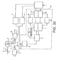
- Fig. 30 shows an example of a conventional optical fiber fusion-splicer having an optical fiber observing image processing apparatus S. The optical fiber observing image processing apparatus S is devised so that connection of an optical fiber can be achieved at a high speed. The optical fiber fusion-splicer includes positioning members A, B shiftable in X -axis, Y-axis and Z-axis directions, and optical fibers (optical fiber core ) C, D having ends to be butted are set in the positioning members. A television camera (camera head) G to which an incident optical system F is attached is disposed in the vicinity of butted portions of the optical fibers C, D and serves to photo-take images of the optical fibers C, D illuminated by an illumination light source E from a direction perpendicular to an optical axes of the fibers. An image photo-taken by the television camera G is processed by the fiber observing image processing apparatus S which will be described later. On the basis of a processed result, a signal is sent from the image processing apparatus S to a control circuit I and a fiber position control circuit J, so that the positioning members A, B are shifted on the basis of the signal to position the optical fibers C, D, the fibers C, D are fusion-connected by discharging between electrode rods H. The fiber observing image processing apparatus S has a function for confirming a condition of end faces of the fibers, as well as a function for controlling the positioning of the fibers C, D.
- The fiber observing image processing apparatus S has a drive circuit K for supplying a synchronous signal and an electric power to the television camera G and for picking-up an image signal from the television camera G. In a rear stage of the drive circuit K, there are provided, in two systems, a capturing portion L for capturing the image signal outputted from the drive circuit K, a data memory M for storing the capturing image data, and a data operator (calculator) N for processing the image data to calculate information for the positioning of the fibers C, D. In one of the systems, a region where the fiber C is reflected is image-processed, and , in the other system, a region where the fiber D is reflected is image-processed, thereby increasing the entire image processing speed.
- In some optical fiber fusion-splicer, three-dimensional positioning is facilitated by photo-taking optical fibers C, D (to be fusion-connected) from two or three directions. In the apparatus in which the fibers are photo-taken from two directions, as shown in Fig. 31A, a mirror R is disposed around the fibers C, D so that the fibers can be photo-taken by a single television camera from two directions simultaneously, or, as shown in Fig. 31B, two television cameras are provided so that the fibers C, D can be photo-taken from different angles. In the latter case, as shown in Fig. 32A, each television camera G is associated with an A/D converter T and a data memory U so that image signals of the television cameras G are captured in parallel to be processed by a data operator P, or, as shown in Fig. 32B, a video switcher V is provided so that the image signals are alternately captured by a single set of an A/D converter T and a data memory U while alternately switching two television cameras G to be processed by a data operator P. In the example shown in Fig. 32B, since a reflection of the television camera G is constituted by a frame image renewed every 1/30 second, two television cameras G are alternately switched by the video switcher V every 1/30 second, so that the image data are captured in the data memory U and the image processing is effected by the data operator P for each of the television cameras G every 1/15 second.
- (1) Since the fiber observing image processing apparatus shown in Fig. 30 has only a single television camera G, it is not suitable for high accurate positioning. Further, due to recent high speed tendency of microprocessors (data operator N), high speed and larger capacity tendency of memories, a data transfer speed and a data calculating speed are increased greatly, even when a single television camera is used, it is not required that the image data is divided into two systems to process the data.
- (2) In the fiber observing image processing apparatus shown in Fig. 3 1A, since two images are photo-taken by the single television camera G, a magnifying power in the optical system cannot be increased, with the result that a resolving power is low in comparison with other photo-taking methods.
- (3) In the fiber observing image processing apparatus shown in Fig. 3 2A, since the optical fibers C, D are photo-taken by two television camera s from plural directions, the positioning accuracy can be improved, and, since the image data from the television cameras G are captured independent ly to process the data, the processing speed can be increased. However, the circuit is complicated to make the entire apparatus expensive and bulky.
- (4) In the fiber observing image processing apparatus shown in Fig. 3 2B, since the signals from two television cameras G are captured into the single capturing system to process the signals, the circuit can be simplified. However, since the images from the respective television cameras G are renewed every 1/15 second, it is difficult to increase the positioning speed.
-
JP-A-9288224 EP-A-0803721 , andJP-A-09 043447 - an image capturing means capable of capturing image data from two or more television cameras and capable of capturing and image-processing only desired image data from each of said television cameras.
- The invention is characterised in the apparatus has two or more different capturing modes for receiving, storing and processing image data, and said capturing modes can automatically be switched in synchronous with or independently from progress of the image processing; said capturing modes include at least one of (i) a capturing mode in which the image data can be captured from said television cameras from frame to frame and the image data from said television cameras can be captured by successively switching said television cameras from frame to frame; and (ii) a capturing mode in which the image data can be captured from said television cameras from field to field and the image data from said television cameras can be capture by successively switching said television cameras from field to field; the capturing modes also include a capturing mode in which the image data can be captured from said television cameras from pixel to pixel and the image data from said television cameras can be captured by successively switching said television cameras from pixel to pixel.
- The capturing means may have a capturing mode in which a field of the respective television camera is divided into two or more so that the desired television camera is assigned to the respective divided field to capture the image data of the plural television cameras into one field in a multiplexing form.
- The capturing means may have a capturing mode in which one scanning line of the respective television cameras is divided into two or more so that the desired television camera is assigned to the respective divided scanning line to capture the image data of the plural television cameras onto one scanning line in a multiplexing form.
- The image data capturing by said image capturing means can be outputted onto a television monitor and the like through a scanning converting means.
- At least two different transfer modes may be provided for transferring of the image data between said image capturing means and said scanning converting means.
- The transfer modes may be automatically be switched in synchronous with or independently from the progress of the image processing.
- The optical fiber observing image processing apparatus may further comprise a delay means capable of setting a desired delay time for image data.
-
- Fig. 1 is a constructional view of an entire optical fiber fusion -splicer using an optical fiber observing image processing apparatus according to the present invention;
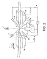
- Fig. 2 is a schematic enlarged view of an optical fiber fusion-splicing portion of Fig. 1;
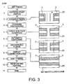
- Fig. 3 is a view for explaining an example of an operation of the optical fiber fusion-splicer of Fig. 1, showing operating steps and change in condition of fibers;
- Fig. 4 is a view for explaining an example of an operation of the optical fiber fusion-splicer of Fig. 1, showing operating steps and change in capturing modes;
- Figs. 5A to 5C are explanatory views showing different examples of a data memory accessing method;
- Fig. 6 is a view for explaining a capturing
mode ③ in an image capturing means; - Fig. 7 is a view for explaining a capturing
mode ④ in the image capturing means; - Fig. 8 is a view for explaining a capturing
mode ⑤ in the image capturing means; - Fig. 9 is a view for explaining a capturing
mode ⑥ in the image capturing means; - Fig. 10 is a view for explaining a capturing
mode ⑦ in the image capturing means; - Fig. 11A is a view showing an image of ribbon fiber photo-taken by a first television camera, and Fig. 11B is a view showing an image of ribbon fiber photo-taken by a second television camera;
- Fig. 12 is an explanatory view showing an example of image capturing in the capturing
mode ⑥; - Fig. 13 is an explanatory view showing an example of image capturing in the capturing
mode ⑦; - Fig. 14 is a schematic view of an entire optical fiber fusion-splicer using an optical fiber observing image processing apparatus according to the present invention, in which a scanning converter is provided;
- Fig. 15 is a circuit diagram showing an example of a circuitry of the optical fiber observing image processing apparatus having the scanning converter;
- Fig. 16 is a circuit diagram showing another example of a circuitry of the optical fiber observing image processing apparatus having the scanning converter;
- Fig. 17 is a circuit diagram of a data memory used in the image capturing means;
- Fig. 18 is a circuit diagram of a scanning converter used as a scanning converting means;
- Fig. 19 is a view for explaining a transfer mode for transferring either an image photo-taken by a first television camera or an image photo-taken by a second television camera;
- Fig. 20 is an explanatory view for explaining a data transferring method in the transfer mode of Fig. 19;
- Fig. 21 is a view for explaining a transfer mode for transferring both an image photo-taken by a first television camera and an image photo-taken by a second television camera;
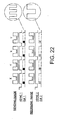
- Fig. 22 is an explanatory view for explaining a data transferring method in the transfer mode of Fig. 19;
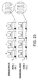
- Fig. 23 is an explanatory view for explaining another example of a data transferring method in the transfer mode of Fig. 19;
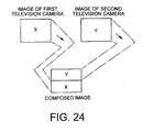
- Fig. 24 is an explanatory view showing another example of a transfer mode for transferring both an image photo-taken by a first television camera and an image photo-taken by a second television camera;
- Fig. 25 is an explanatory view for explaining a data transferring method in the transfer mode of Fig. 24;
- Fig. 26 is an explanatory view for explaining another example of a data transferring method in the transfer mode of Fig. 24;
- Fig. 27 is a circuit diagram showing another example of a circuitry of the optical fiber observing image processing apparatus having the scanning converter;
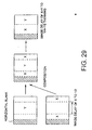
- Fig. 28 is an explanatory view showing an example of picture plane composition utilizing a delay circuit;
- Fig. 29 is an explanatory view showing another example of picture plane composition utilizing a delay circuit, when a horizontal direction and a vertical direction of a television camera is replaced;
- Fig. 30 is a schematic view showing an example of a conventional optical fiber fusion-splicer;
- Fig. 31A is an explanatory view for explaining a case where photo-taking is effected by a single camera from two directions, and Fig. 31B is an explanatory view for explaining a case where photo-taking is effected by two cameras; and
- Fig. 32A is a schematic view of an image processing apparatus in which image capturing systems are provided for respective cameras, and Fig. 32B is a schematic view of an image processing apparatus in which images from two cameras are captured by a single image capturing system.
- Fig. 1 is a schematic view of an entire optical fiber fusion-splicer constituted by using an optical fiber observing
image processing apparatus 27 according to the present invention, and Fig. 2 is an enlarged view of an optical fiber fusion-splicing portion. In this optical fiber fusion-splicer, as shown in Figs. 1 and 2, butted portions (portions to be butted) ofoptical fibers television cameras 1.Respective television cameras 1 are set to photo-take butted portions ofoptical fibers television camera 1 is constituted by attaching an incidentoptical system 10 for photo-taking thefibers illumination light sources 11 opposite to therespective television cameras 1 with the interposition of theoptical fibers optical fibers television camera 1 serves to output a video signal of NTSC system. On the basis of a synchronous signal from aninput processing circuit 13 of the optical fiber observingimage processing apparatus 27 according to the present invention, the television cameras output synchronized video signals. - In the optical fiber observing
image processing apparatus 27 shown in Fig. 1, the video signals of NTSC system outputted from the first andsecond television cameras 1 are inputted to theinput processing circuit 13 , where optimum video signals of thetelevision cameras 1 are selected under control of an R/W control circuit 12. The video signals are A/D-converted in an A/D converter 22 to obtain image data which are then written in a data memory (image capturing means) 14. Thedata memory 14 has capacity corresponding to two picture planes, and, for the writing (capturing) of the picture plane data in thedata memory 14, three new capturing modes are provided, in addition to an existing capturing mode. Modes provided in the image capturing means - Capturing mode ①: in this mode, the image from the
first television camera 1 is written in thedata memory 14. - Capturing mode ②: in this mode, the image from the
second television camera 1 is written in thedata memory 14. - Capturing mode ③: in this mode, as shown in Fig. 6, the first and
second television cameras 1 are alternately switched from frame to frame (every 1/30 second), and the images from thetelevision cameras 1 are alternately written in thedata memory 14 from frame to frame. Intelevision cameras 1 of interlaced type, images having odd (ODD) fields and even ( EVEN) fields from thefirst television camera 1 are written, and then images having odd fields and even fields from thesecond television camera 1 are written. - Capturing mode ④: in this mode, as shown in Fig. 7, the first and
second television cameras 1 are alternately switched from field to field (every 1/60 second), and the images from thetelevision cameras 1 are alternately written in thedata memory 14 from field to field. - Capturing mode (5): in this mode, as shown in Fig. 8, the first and
second television cameras 1 are switched from pixel to pixel, and the images from twotelevision cameras 1 are both written in thedata memory 14. - As shown in Fig. 5A, in the data memory 14 (Fig. 1), one pixel component (8 bits) of memory access can be written by three times within a period of one pixel component of the
television camera 1. The access can be effected as only write-in (W) of three times or only read-out (R) of three times, and, as shown in Fig. 5B, read-out (R) of two times and write-in (W) of one time may be made, or, as shown in Fig. 5C, read-out (R) of one time and write-in (W) of two times may be made. Since the accessing method shown in Fig. 5B includes read-out (R) of two times and write-in (W) of one time, this method corresponds to the image capturing means including the capturingmode ③ and the capturingmode ④, and, since the accessing method shown in Fig. 5C includes read-out (R) of one time and write-in (W) of two times, this method corresponds to the image capturing means including the capturingmode ⑤. Accordingly, the accessing method shown in Fig. 5B in which read-out (R) can be effected by two times is suitable for effecting operations frequently and thus suitable for the image processing in an initial step of the fiber fusion-splice when thefibers fibers - In a
data operator 15 shown in Fig. 1, the image processing of the image data stored in thedata memory 14 is performed, and, on the basis of a processed result, signals are outputted to acontrol circuit 16 and agraphic circuit 17 of Fig. 1. Regarding the processing in the data operator, the image data is read-out from thedata memory 14, such data is processed so that information regarding deviation of optical axes of theoptical fibers control circuit 16 and thegraphic circuit 17. The signal outputted to thecontrol circuit 16 is outputted to asecond driving device 26 through a fiberposition control circuits positioning members optical fibers positioning members - When information regarding progress of the image processing and information such as image processing result are outputted from the
data operator 15 as data, the graphic circuit 17 (Fig. 1) forms text (characters) and/or graphic (figure) and outputs them to avideo encoder 29 as a video signal. For example, text information indicating content or condition of the image processing and graphic information indicating measurement lines of theoptical fibers - The video encoder 29 (Fig. 1) serves to compose the image signal outputted from the
input processing circuit 13 with the video signal from thegraphic circuit 17 to output a single signal. This video signal is inputted to atelevision monitor 25. - Fig. 3 shows an operating steps of the optical fiber fusion-splic er, together with images displayed on the television monitor, and Fig. 4 shows a relationship between the operating steps and the capturing modes. Now, the operating steps and the capturing modes will be described.
- 1. After the
optical fibers 2, 3 (from which coatings were removed and in which end portions of the fibers were prepared) are set on thepositioning members data memory 14 in the capturingmode ④, and theoptical fibers steps 1 to 3 in Figs. 3 and 4). - 2. Weak discharging of
electrode rods 24 is started, thereby cleaning end portions of theoptical fibers 2, 3 (step 4 in Figs. 3 and 4). - 3. The images photo-taken by the first and second television cameras are captured into the
data memory 14 in the capturingmode ⑤, and the image processing is effected in thedata operator 15. In this stage, it is checked whether or not cut angles of the end faces of theoptical fibers step 5 in Figs. 3 and 4). - 4. If there is no abnormality in the end faces, the data is further captured into the
data memory 14 in the capturingmode ⑤ and the image processing is effected in thedata operator 15. In this stage, the optical axes of theoptical fibers first television camera 1 is effected, followed by centering regarding the image from thesecond television camera 1, and detection of deviation between the axes and detection of distance between the end faces are carr ied out (step 6 in Figs. 3 and 4). - 5. After the discharging condition is set, strong discharging is effected, and fusion-splicing is effected by approaching the
optical fibers step 7 in Figs. 3 and 4). - 6. After the connection is completed, fused and spliced portions of the
optical fibers step 8 in Figs. 3 and 4). - 7. A reinforcing member (heat-shrinkable tube and rod-shaped reinforcing element are frequently used) is applied to the fused and spliced portions of the
optical fibers optical fibers steps 9 to 11 in Figs. 3 and 4). - In the optical fiber observing image processing apparatus according to the present invention, in addition to the capturing
modes ① to ⑤, the following two capturingmodes such capturing modes ① to ⑦ in accordance with progress of the image processing into thedata operator 15, high speed and high accurate image processing can be achieved. - Capturing mode ⑥: in this mode, the images from two
television cameras 1 are switched at predetermined scanning lines, and, as shown in Fig. - 9, the images are divided and are written in the
data memory 14 in the multiplex form. For example, after the image data of a front half of the 0DD field of thesecond television camera 1 is captured, the input is switched to capture the image data of a rear half of the ODD field of thefirst television camera 1. By repeating such operation, the images from twotelevision cameras 1 are divided into respective fields which can be in turn written in the multiplex form. Fig. 12 shows an example of image capturing in the capturingmode ⑥, in which the image from thefirst television camera 1 and the image from thesecond television camera 1 are simultaneously displayed on lower and upper parts of thetelevision monitor 25, respectively. Incidentally, at a glance, the images includes a plurality (two ) ofoptical fibers - Capturing mode ⑦: in this mode, the images from two
television cameras 1 are switched at predetermined pixels of scanning lines, and, as shown in Fig. 10, the images are divided and are written in thedata memory 14 in the multiplex form so that two images are captured simultaneously. For example, after the image data of a front half of one scanning line of the 0DD field of thefirst television camera 1 is captured, the input is witched to capture the image data of a rear half of one scanning line of the - 0DD field of the
second television camera 1. Such an operation is performed for every scanning line in one field. Fig. 13 shows an example of image capturing in the capturingmode ⑦, in which the first andsecond television cameras 1 are both rotated by 90 degrees to change vertical and horizontal directions, and the images are photo-taken, and then the images are composed. - Fig. 14 shows a second embodiment of an optical fiber observing
image processing apparatus 27 according to the present invention. In this embodiment, a scanning converter (scanning converting means) 30 is incorporated into the optical fiber observingimage processing apparatus 27 according to the first embodiment so that the image data captured in thedata memory 14 can be displayed on thetelevision monitor 25 through thescanning converter 30. In this case, two or more different transfer modes for transferring the image data between thedata memory 14 and thescanning converter 30 can be provided. By selection of the transfer modes and selection of the capturing modes, for example, the followingoperation modes ① to ⑤ can be selected and switched on the basis of program. Incidentally, thescanning converter 30 serves to adjust longitudinal magnification, lateral magnification, longitudinal offset amount and lateral offset amount of the inputted image. - Operation mode ①: in this mode, the image data from either the first or
second television camera 1 is captured and is displayed. Regarding thedata memory 14, the proper mode (for example, capturingmode ① or ②) is selected among the above-mentioned capturing modes, and the image data from the first orsecond television camera 1 is recorded in the data memory. In the transferring (transfer mode) of data from thedata memory 14 to thescanning converter 30, as shown in Fig. 20, a horizontal synchronous signal IISYNC1 of the sending side (data memory 14 side) and a horizontal synchronous signal HSYNC2 of the receiving side (scanningconverter 30 side) have the same timing. Further, a verticalsynchronous signal VSYNC 1 of the sending side and a vertical synchronous signal VSYNC2 of the receiving side have the same timing. In addition, pixel clock signals (not shown) of the sending and receiving sides have the same timing. The sending side and the receiving side are subjected to interlaced operation. Fig. 20 shows an example when the capturing mode is selected, in which the image data from thefirst television camera 1 is captured into thedata memory 14 and the image from thefirst television camera 1 is displayed on the television monitor 25 (Fig. 19). - Operation mode ②: in this mode, the image data from both the first and the
second television camera 1 are captured and are displayed on left and right half parts of the television monitor, as shown in Fig. 21. Regarding thedata memory 14, the capturing mode capable of capturing the images from twotelevision cameras 1 is selected and the image data from the first andsecond television cameras 1 are recorded in the data memory. In the transferring (transfer mode) of data from thedata memory 14 to thescanning converter 30, as shown in Fig. 22, whenever a horizontal synchronous signal HSYNC1 of the sending side is switched, the image data from the first television camera and the image data from the second television camera are alternately switched to be outputted. In the receiving side, a horizontal synchronous signal HSYNC2 is set to a half period of the horizontal synchronous signal HSYNC1 of the sending side, and a pixel clock signal CLK2 is set to a half period of a pixel clock signal CLK1 of the sending side, and a vertical synchronous signal VSYNC2 is set to the same period of a vertical synchronous signal VSYNC1 of the sending side. Although the image data of thefirst television camera 1 and the image data of the second television camera 1 (disposed side by side) are transferred from the data memory 14 (as two picture planes), since the pixel data are thinned on alternate pixels to be transferred, a two picture plane image as shown in Fig. 21 can be obtained. - Operation mode ③: as is in the
operation mode ②, in this mode, the image data from both the first and thesecond television camera 1 are captured and are displayed on left and right half parts of the television monitor, as shown in Fig. 21. As shown in Fig. 23, in this mode, in the transferring of data, a pixel clock signal CLK1 of the sending side is set to be the same as a pixel clock signal CLK2 of the receiving side, and, by compressing the image to 1/2 in a horizontal direction in thescanning converter 30, the image shown in Fig. 21 (same as the image in the capturing mode of Fig. 22, at a glance) is displayed. However, the image data is transferred to thescanning converter 30 without thinning. - Operation mode ④: in this mode, the image data from both the first and the
second television camera 1 are captured and are displayed on lower and upper half parts of the television monitor, as shown in Fig. 24. Regarding thedata memory 14, the capturing mode capable of capturing the images from twotelevision cameras 1 is selected and the image data from the first and second television cameras are recorded in the data memory. In the transferring (transfer mode) of data from thedata memory 14 to thescanning converter 30, as shown in Fig. 25, whenever a vertical synchronous signal VSYNC1 of the sending side is switched, the image data from the first television camera and the image data from the second television camera are alternately switched to be outputted. In the receiving side, a vertical synchronous signal VSYNC2 is set to a half period of the vertical synchronous signal VSYNC1 of the sending side. Although the image data of thefirst television camera 1 and the image data of the second television camera 1 (disposed side by side in the vertical direction) are transferred from the data memory 14 (as two picture planes), since one side fields of the images from therespective television cameras 1 are transferred, a two picture plane image as shown in Fig. 24 can be obtained. - Operation mode ⑤: as is in the
operation mode ④, in this mode, the image data from both the first and thesecond television camera 1 are captured and are displayed on lower and upper half parts of the television monitor, as shown in Fig. 24. In this mode, both the sending side and the receiving side are subjected to non-interlaced operation. Whenever a vertical synchronous signal VSYNC1 of the sending side is switched, as shown in Fig. 26, the image data from the first television camera and the image data from the second television camera are alternately transferred from frame to frame. Further, a vertical synchronous signal VSYNC2 of the receiving side is set to a half period of the vertical synchronous signal VSY NC1 of the sending side. By compressing the image to 1/2 in a vertical direction in thescanning converter 30, the image shown in Fig. 24 (same as the image in the capturing mode of Fig. 25, at a glance) is displayed. However, the image data is transferred to thescanning converter 30 without thinning. - By constructing the program in such a manner that, when the optical fibers are shifted at a high speed, i.e., when the image is renewed at a high speed, the
operation mode operation mode - Fig. 15 shows a third embodiment of an optical fiber observing
image processing apparatus 27 according to the present invention. In this embodiment, there are provided first and secondinput processing circuits D converters a.data memory 35 for storing the A/D-converted image data, aselector 37 for switching the image data of thedata memory 35 to send the data to ascanning converter 36 which adjusts longitudinal magnification, lateral magnification, longitudinal offset amount a nd lateral offset amount of the image, a D/A converter 38 for D/A-converting the image data from thescanning converter 36, adata operator 39 for processing the image data stored in thedata memory 35, agraphic circuit 4 0 for forming various graphics on the basis of the processing in thedata calculator 39, avideo encoder 41 for composing the image data from thescanning converter 36 with the image data from thegraphic circuit 40, and asynchronous signal generator 42 for generating an output side synchronous signal. That is to say, the image data outputted from thefirst television camera 1 and thesecond television camera 1 and stored in thedata memory 35 is selected by theselector 37 and the selected data is sent to thescanning converter 36 so that the image data from thefirst television camera 1, the image data from thesecond television camera 1 or the image data obtained by composing the image data from both cameras with each other is outputted through thescanning converter 36. - Fig. 16 shows a fourth embodiment of an optical fiber observing
image processing apparatus 27 according to the present invention. In this embodiment, thescanning converter 36 of the optical fiber observingimage processing apparatus 27 of Fig. 15 can be controlled by thedata calculator 39 and the image data from thescanning converting device 36 is transferred to thedata calculator 39 to permit data processing. In this case, since the image data stored in thedata memory 35 and the image data stored in thescanning converter 36 can be image-processed on demand, for example, processing in which the image data being captured presently is compared with the image data of previous frame can be effected. Further, since data not requiring real time ability can be divided and stored in both thedata memory 35 and thescanning converter 36, the load of the entire image processing apparatus can be reduced. In this case, the operating frequency of the image processing apparatus is decreased to save an electric power, thereby reducing the running cost. - In the optical fiber observing
image processing apparatuses 27 of the present invention shown in Figs. 15 and 16, theinput processing circuits D converters A converter 38 are available from the market, and thedata memory 35 and thescanning converter 36 can easily be obtained from the market so long as they have the following construction or the similar function. - The
data memory 35 shown in Fig. 16 comprises animage controller 43 and animage memory 44 as shown in Fig. 17, and theimage controller 4 3 is constituted by a write-inaddress forming circuit 45, animage input buffer 46, aCPU interface 47, animage memory interface 48, a read-outaddress forming circuit 49 and animage output buffer 50. The image data is captured into theimage input buffer 46 through image input ports PI0 to PI7 in synchronous with clock PICLK inputted to the image input port. In this case, in the write-inaddress forming circuit 45, write-in address is formed in accordance with a field discrimination signal PIFLD inputted to the image input port, a signal PIVS indicating a picture plane start position (upper edge of picture plane), a signal PIHS indicating a column start position (left edge of picture plane) and clock PICLK, and, on the basis of such address, the data transferred to theinput buffer 46 is transfer red to theimage memory 44 through theimage memory interface 48. Theimage memory interface 48 serves to control an input side, an output side,C PU interface 47 and image memory 44 (intervention of refresh operation of the image memory may be effected in dependence upon the kind of the image memory). The image data stored in theimage memory 44 is read-out through theimage memory interface 48 on the basis of read-out address formed in the read-out address forming circuit 49 (which address is formed on the basis of a field discrimination signal POFLD inputted to an image output port , a signal POVS indicating a picture plane start position (upper edge of picture plane), and a signal POHS indicating a column start position (left edge of picture plane)), and the read-out data is transferred to theimage output buffer 50. In theimage output buffer 50, the image data is outputted to image output ports P00 to P07 in synchronous with clock POCLK inputted to the image output port. - The
scanning converter 36 of Fig. 16 comprises animage processing processor 51 and animage memory 52, as shown in Fig. 18, and theimage processing processor 51 is constituted by a write-inaddress forming circuit 53, animage input buffer 54, aCPU interface 55, animage memory interface 56, a read-outaddress forming circuit 57, an image output buffer 58, a n address converting table 59 and an interpolation operational circuit 60. Thisimage processing processor 51 is constituted by adding the address converting table 59 and the interpolation operational circuit 60 to theimage controller 43 of thedata memory 35, and writing-in of the image data in theimage memory 52 and reading-out of the image data from theimage memory 52 are fundamentally effected in the same manner as thedata memory 35. However, the address converting table 59 and the interpolation operation al circuit 60 are provided, and the address converting table 59 is provided with an address converting function for rotating the image by 90 degrees, and the interpolation operational circuit 60 is provided with a function for correcting the pixel data when the number of pixels is increased or decreased, so that, the picture plane can be displayed even when the number of pixels in the vertical and horizontal directions is changed by rotating the picture plane by 90 degrees and contraction or enlargement of the picture plane is required in dependence upon the pixel data transfer mode between the frontstage data memory 35 and thescanning converter 36. In the mode in which the thinning is effected with integral times of a ratio between the number of pixels in the vertical direction and the number of pixels in the horizontal direction, merely passing may be made (for example, the thinning as shown in Fig. 25 is effected to obtain the picture plane as shown in Fig. 24). Incidentally, as the address converting table 59, a memory IC (ROM, RAM) in which the data after rotated by 90 degrees is previously stored, a device for writing-in connection of operational circuit (PLD: programmable logic device) or a device for writing-in operation program (AL U: arithmetic and logic unit) may be used. - Fig. 27 shows a fifth embodiment of a fiber observing
image processing apparatus 27 according to the present invention. In this embodiment , there are provided first and secondinput processing circuits D converters data memory 35, afirst delay circuit 61 for effecting delay treatment of the image data from thesecond television camera 1, aselector 37, asecond delay circuit 62 disposed between theselector 37 and ascanning converter 36, thescanning converter 36, a D/A converter 38, adata operator 39, agraphic circuit 40, avideo encoder 41 and asynchronous signal generator 42. - Each of the first and
second delay circuits television cameras 1 on left and right half parts of the television monitor, and a difference between Fig. 28 and Fig. 29 is that thetelevision cameras 1 are installed vertically and are laid laterally. In both cases, the image from the second television camera is delayed by an amount corresponding to 1/2 picture plane by thefirst delay circuit 61, and the image composed by theselector 37 is delayed by an amount corresponding to 1/4 picture plane by thesecond delay circuit 62, and the image data is thinned to 1/2 between thesecond delay circuit 62 and thescanning converter 36, with the result that the images from the first and second television cameras can be displayed side by side in the left-and-right direction. - The present invention can be applied to the following optical fiber observing image processing apparatuses:
- 1. The
television cameras 1 may be of PAL type or SECAM type, as well as NTSC type. - 2. Although the capturing mode shown in Fig. 7 is limited to the interlaced system, the capturing mode (3) and capturing mode (5) can be used in the non-interlaced system.
- 3. The number of the television cameras is not limited to two, but may be three, four or more.
- 4. The number of accesses to the data memory may be three or more for each pixel.
- 5. The optical fiber observing image processing apparatus according to the present invention can be constituted by using a digital signal processor (DSP) and software program.
- 6. The transferring of the image data between the
data memory 35 shown in Figs. 15 or 16 and thescanning converter 36 may be synchronous with an input video signal of thetelevision camera 1 or an output video signal to the television monitor or both or may not be synchronized, so long as the renewal of the picture plane can be achieved. - 7. The
scanning converter 30 shown in Fig. 14 may adjust the longitudinal magnification, lateral magnification, longitudinal offset amount, lateral offset amount and rotational amount of the inputted image. - 8. Regarding the installation of the
television cameras 1, orientation of the scanning lines may be in parallel or perpendicular to the axes of theoptical fibers - According to the optical fiber observing image processing apparatus of the present invention, the following advantages can be obtained:
- 1. Since the optical fibers can be photo-taken from plural directions by using two television cameras, high accurate image processing can be achieved and high accurate positioning can be made.
- 2. The image processing can be performed by switching a plurality of different capturing modes provided in the image capturing means. For example, by effecting the image processing by switching a capturing mode having a high resolving power and a capturing mode having a low resolving power and high speed processing ability, a processing speed of the entire fusion -splicing process can be increased.
- 3. Since the plurality of different capturing modes can be switched, even when a single system for the image capturing circuit is used, the desired image processing performance can be achieved, thereby making the image processing apparatus cheaper and more compact.
- 4. Since the plurality of capturing modes including the capturing mode for switching the television cameras from frame to frame, the capturing mode for switching the television cameras from field to field and the capturing mode for switching the television cameras from pixel to pixel are provided and such capturing modes can be switched, even in optical fiber fusion-splice having a plurality of processing steps, by selecting the proper capturing mode, the processing can be effected with high accuracy at a high speed.
- 5. By utilizing the capturing mode in which the single field is divided into two or more and the desired television cameras are assigned to the respective divided fields to capture the image data from the plural television cameras into one field in a multiplex form, the image from the plural television cameras can be captured into a field for one picture plane in a multiplex form.
- 6. By utilizing the capturing mode in which the single scanning line is divided into two or more and the desired television cameras are assigned to the respective divided scanning lines to capture the image data from the plural television cameras on one scanning line in a multiplex form, the e image from the plural television cameras can be captured into a field for one picture plane in a multiplex form.
- 7. Since the image data captured by the image capturing means can be outputted to the television monitor through the scanning converting means, the picture plane can be displayed on the television monitor with required treatment such as enlargement, contraction, offset or rotation of the picture plane.
- 8. Since at least two transfer modes for transferring the image data between the image capturing means and the scanning converting means are provided, in each step of the optical fiber fusion-splice, the transfer mode suitable for the step can be selected. Accordingly, the proper image processing can be effected by using the proper displayed picture plane, thereby providing high speed processing, high accuracy and good visibility.
- 9. By providing the plurality of modes for transferring the data between the image capturing means and the scanning converting means, since the data memory used in the image capturing means and the image processing controller used in the scanning converter can easily be obtained from the market, conventional LSI and gate array are available, thereby making the apparatus more compact and cheaper and saving an electric power.
- 10. By providing the delay means capable of setting the desired delay time for the image data, enlargement, contraction or offset of the image can be effected without the scanning converter.
Claims (7)
- An optical fiber observing image processing, apparatus (27) in which positioning or optical axes and end faces of optical fibers (2, 3) can be automatically controlled by capturing and processing image data of the optical fibers (2,3) photo-taken by television cameras (1), comprising:an image receiving means (13) for receiving image data from two or more television cameras (1) and including, an analogue to digital converter (22), data memory for storing image data from said television cameras (1), and data processing means for processing the stored data; a data the apparatus (27) having two or more different capturing modes for receiving storing and processing image data, whereby said capturing modes can automatically be switched in synchronous with or independently from progress of the image processing; the apparatus being characterized in that said capturing modes include at least one of:i) a capturing mode in which the image data can be captured from said television cameras (1) from frame to frame and the image data from said television cameras (1) can be captured by successively switching between said television camera from frame to frame; andii) a capturing mode in which the image data can be captured from said television cameras (1) from field to field and the image data from said television cameras (1) can be captured by successively switching between said television cameras (1) from field to field;the capturing modes also include a capturing mode in which the image data can be captured from said television cameras (1) from, pixel to pixel and the image data from said television cameras (1) can be captured by successively switching between said television cameras (1) from pixel to pixel.
- An optical fiber observing image processing apparatus as claimed in claim 1, wherein said apparatus (27) has a capturing mode in which a field of the respective television camera (1) is divided into two or more so that the desired television camera (1) is assigned to the respective divided field to capture the image data of the plural television cameras (1) into one field in a multiplexing form.
- An optical fiber observing image processing apparatus as claimed in claim 1 or 2, wherein said apparatus (27) has a capturing mode in which one scanning line of the respective television cameras (1) is divided into two or more so that the desired television camera (1) is assigned to the respective divided scanning line to capture the image data of the plural television cameras (1) onto one scanning line in a multiplexing form.
- An optical fiber observing image processing apparatus as claimed in a one preceding claim, wherein the image data capturing by said apparatus (27) can be outputted onto a television monitor (25) and the like through a scanning converting means (30).
- An optical fiber observing image processing apparatus as claimed in claim 4, wherein at least two different transfer modes are provided for transferring of as image data between said apparatus (27) and said scanning converting means (30).
- An optical fiber observing image processing apparatus as claimed in claim 5, wherein said transfer modes can automatically be switched in synchronous with or independently from the progress of the image processing.
- An optical fiber observing image processing apparatus as claimed in any one preceding Claim, further comprising a delay means (61, 62) capable of setting a desired delay time for image data.
Applications Claiming Priority (3)
| Application Number | Priority Date | Filing Date | Title |
|---|---|---|---|
| JP6859698 | 1998-03-18 | ||
| JP6859698 | 1998-03-18 | ||
| PCT/JP1999/000445 WO1999047903A1 (en) | 1998-03-18 | 1999-02-03 | Image processor for observing optical fiber |
Publications (3)
| Publication Number | Publication Date |
|---|---|
| EP0984259A1 EP0984259A1 (en) | 2000-03-08 |
| EP0984259A4 EP0984259A4 (en) | 2000-04-19 |
| EP0984259B1 true EP0984259B1 (en) | 2007-11-21 |
Family
ID=13378343
Family Applications (1)
| Application Number | Title | Priority Date | Filing Date |
|---|---|---|---|
| EP99902815A Expired - Lifetime EP0984259B1 (en) | 1998-03-18 | 1999-02-03 | Image processor for observing optical fiber |
Country Status (6)
| Country | Link |
|---|---|
| US (1) | US7061522B1 (en) |
| EP (1) | EP0984259B1 (en) |
| KR (1) | KR20010012716A (en) |
| CA (1) | CA2290359A1 (en) |
| DE (1) | DE69937595D1 (en) |
| WO (1) | WO1999047903A1 (en) |
Families Citing this family (13)
| Publication number | Priority date | Publication date | Assignee | Title |
|---|---|---|---|---|
| JP4531925B2 (en) * | 2000-04-26 | 2010-08-25 | 古河電気工業株式会社 | Observation equipment for optical fibers and optical components |
| SE530854C2 (en) * | 2005-12-30 | 2008-09-30 | Ericsson Telefon Ab L M | Alignment of optical fibers in their jointing |
| DE102006023828B4 (en) * | 2006-05-20 | 2011-04-28 | Schott Ag | Method and device for checking the faces of optical fibers |
| DE102006028693A1 (en) * | 2006-06-22 | 2007-12-27 | CCS Technology, Inc., Wilmington | Video system for a splicer and method of operating a video system for a splicer |
| US8998511B2 (en) | 2008-07-08 | 2015-04-07 | Telefonaktiebolaget L M Ericsson (Publ) | Cladding alignment for fusion splicing optical fibers |
| USD652850S1 (en) * | 2009-10-14 | 2012-01-24 | Ilsin Tech Co., Ltd. | Optical fiber fusion splicer |
| USD652212S1 (en) * | 2010-05-20 | 2012-01-17 | Sumitomo Electric Industries, Ltd. | Carrying case for an optical fiber fusion splicer |
| EP2669725B1 (en) * | 2011-01-24 | 2015-12-30 | Fujikura Ltd. | Fusion splicing apparatus and fusion splice method |
| USD652438S1 (en) * | 2011-02-09 | 2012-01-17 | Furukawa Electric Co., Ltd. | Optical fiber fusion splicer |
| US9880105B2 (en) | 2011-06-21 | 2018-01-30 | Afl Telecommunications Llc | Method for pre and post image association in fiber optic inspection |
| JP6421348B2 (en) * | 2015-01-23 | 2018-11-14 | Seiオプティフロンティア株式会社 | Optical fiber fusion splicing device and optical fiber fusion splicing method |
| GB2536468A (en) * | 2015-03-18 | 2016-09-21 | Stratec Biomedical Ag | Device, system and method for the visual alignment of a pipettor tip and a reference point marker |
| JP7118911B2 (en) * | 2019-03-08 | 2022-08-16 | 株式会社東芝 | Image processing device |
Citations (7)
| Publication number | Priority date | Publication date | Assignee | Title |
|---|---|---|---|---|
| JPS5447671A (en) * | 1977-09-21 | 1979-04-14 | Nippon Telegr & Teleph Corp <Ntt> | Monitoring device for axial alignment of optical fibers |
| JPS62144004A (en) * | 1985-12-18 | 1987-06-27 | Sumitomo Electric Ind Ltd | Image processing circuit for optical fiber connection |
| JPS63222206A (en) * | 1987-03-11 | 1988-09-16 | Sumitomo Electric Ind Ltd | Image processing device for measuring optical fiber structure |
| EP0400408A2 (en) * | 1989-06-02 | 1990-12-05 | Siemens Aktiengesellschaft | Method for aligning two fibre ends and apparatus for its implementation |
| JPH0943447A (en) * | 1995-07-27 | 1997-02-14 | Fujikura Ltd | Optical fiber fusion splicer |
| EP0803721A2 (en) * | 1996-04-23 | 1997-10-29 | Sumitomo Electric Industries, Ltd. | Method and apparatus for observing tip portion of optical fibers butting each other |
| EP0813081A1 (en) * | 1996-06-12 | 1997-12-17 | Siemens Aktiengesellschaft | Procedure to determine the inclination angle of at least one optical fibre and device to carry out the procedure |
Family Cites Families (13)
| Publication number | Priority date | Publication date | Assignee | Title |
|---|---|---|---|---|
| US4523226A (en) * | 1982-01-27 | 1985-06-11 | Stereographics Corporation | Stereoscopic television system |
| JPS62206996A (en) * | 1986-03-07 | 1987-09-11 | Hitachi Ltd | Light replacing method and device therefor |
| JPS62265878A (en) * | 1986-05-13 | 1987-11-18 | Sony Corp | Monitor device |
| JPH01107218A (en) * | 1987-10-21 | 1989-04-25 | Nippon Telegr & Teleph Corp <Ntt> | Device for observing juncture of tape type multicored optical fiber |
| JPH0233108A (en) * | 1988-07-23 | 1990-02-02 | Fujikura Ltd | Connecting method for optical fiber |
| JPH0237306A (en) * | 1988-07-27 | 1990-02-07 | Fujikura Ltd | Method of inspecting juncture of multiple optical fiber |
| JPH02122556A (en) * | 1988-10-31 | 1990-05-10 | Nec Corp | Method of mounting semiconductor device |
| FR2640040B1 (en) * | 1988-12-05 | 1994-10-28 | Micro Controle | OPTICAL MEASUREMENT METHOD AND DEVICE |
| JP3220538B2 (en) * | 1992-12-24 | 2001-10-22 | オリンパス光学工業株式会社 | Stereoscopic endoscope and stereoscopic endoscope device |
| JP3397937B2 (en) | 1995-06-14 | 2003-04-21 | 古河電気工業株式会社 | Optical fiber image processing method |
| JPH09288224A (en) * | 1996-04-22 | 1997-11-04 | Fujikura Ltd | Core position estimation method and alignment method for multi-core optical fiber |
| JP3389595B2 (en) * | 1997-06-26 | 2003-03-24 | 住友電気工業株式会社 | Optical fiber observation device and fusion splicing device |
| JP3176574B2 (en) * | 1997-10-15 | 2001-06-18 | 住友電気工業株式会社 | Optical fiber observation device and optical fiber fusion splicer |
-
1999
- 1999-02-03 US US09/423,461 patent/US7061522B1/en not_active Expired - Fee Related
- 1999-02-03 WO PCT/JP1999/000445 patent/WO1999047903A1/en not_active Ceased
- 1999-02-03 DE DE69937595T patent/DE69937595D1/en not_active Expired - Lifetime
- 1999-02-03 CA CA002290359A patent/CA2290359A1/en not_active Abandoned
- 1999-02-03 EP EP99902815A patent/EP0984259B1/en not_active Expired - Lifetime
- 1999-02-03 KR KR1019997010677A patent/KR20010012716A/en not_active Ceased
Patent Citations (7)
| Publication number | Priority date | Publication date | Assignee | Title |
|---|---|---|---|---|
| JPS5447671A (en) * | 1977-09-21 | 1979-04-14 | Nippon Telegr & Teleph Corp <Ntt> | Monitoring device for axial alignment of optical fibers |
| JPS62144004A (en) * | 1985-12-18 | 1987-06-27 | Sumitomo Electric Ind Ltd | Image processing circuit for optical fiber connection |
| JPS63222206A (en) * | 1987-03-11 | 1988-09-16 | Sumitomo Electric Ind Ltd | Image processing device for measuring optical fiber structure |
| EP0400408A2 (en) * | 1989-06-02 | 1990-12-05 | Siemens Aktiengesellschaft | Method for aligning two fibre ends and apparatus for its implementation |
| JPH0943447A (en) * | 1995-07-27 | 1997-02-14 | Fujikura Ltd | Optical fiber fusion splicer |
| EP0803721A2 (en) * | 1996-04-23 | 1997-10-29 | Sumitomo Electric Industries, Ltd. | Method and apparatus for observing tip portion of optical fibers butting each other |
| EP0813081A1 (en) * | 1996-06-12 | 1997-12-17 | Siemens Aktiengesellschaft | Procedure to determine the inclination angle of at least one optical fibre and device to carry out the procedure |
Also Published As
| Publication number | Publication date |
|---|---|
| DE69937595D1 (en) | 2008-01-03 |
| WO1999047903A1 (en) | 1999-09-23 |
| CA2290359A1 (en) | 1999-09-23 |
| EP0984259A4 (en) | 2000-04-19 |
| EP0984259A1 (en) | 2000-03-08 |
| KR20010012716A (en) | 2001-02-26 |
| US7061522B1 (en) | 2006-06-13 |
Similar Documents
| Publication | Publication Date | Title |
|---|---|---|
| US7061522B1 (en) | Optical fiber fusion-splicer | |
| JP3500850B2 (en) | Method and apparatus for observing butted portion of ribbon-type optical fiber | |
| EP0645926A1 (en) | Image processing apparatus | |
| US6549650B1 (en) | Processing of image obtained by multi-eye camera | |
| EP0707226A1 (en) | Apparatus and method of splicing polarization-maintaining optical fibers | |
| CN106406016A (en) | Three-dimensional imaging device, three-dimensional imaging system and three-dimensional imaging method | |
| JPH0229172A (en) | Automatic focus adjusting device | |
| US20040119882A1 (en) | Imaging apparatus and coupling apparatus for use therewith | |
| JP3752095B2 (en) | Image processing device for optical fiber observation | |
| JPH11326681A (en) | Image processing equipment for optical fiber observation | |
| EP1055902A1 (en) | Image processor for observing optical fiber and optical fiber fusion-connecting device | |
| JP4531925B2 (en) | Observation equipment for optical fibers and optical components | |
| EP0977025A1 (en) | Image processor for observing optical fibers | |
| CN1238818C (en) | Imaging method and system for 2D 360 deg panorama based on color linear CCD | |
| JPH1114855A (en) | Optical fiber observation device and fusion splicing device | |
| JPH1114316A (en) | Appearance condition observation device | |
| JPH07193690A (en) | Image reader | |
| JP3397937B2 (en) | Optical fiber image processing method | |
| JP3142751B2 (en) | Optical fiber fusion splicer | |
| JPH09102967A (en) | Stereoscopic device | |
| JPH08271798A (en) | Plural-head microscope | |
| JP3078913B2 (en) | Alignment and Number of Hearts Confirmation Method by Image Processing of Optical Fiber | |
| JP2635763B2 (en) | Observation method of multi-core optical fiber | |
| JPH0618771A (en) | Autofocus device in magnification imaging device | |
| JPS62144004A (en) | Image processing circuit for optical fiber connection |
Legal Events
| Date | Code | Title | Description |
|---|---|---|---|
| PUAI | Public reference made under article 153(3) epc to a published international application that has entered the european phase |
Free format text: ORIGINAL CODE: 0009012 |
|
| 17P | Request for examination filed |
Effective date: 19991119 |
|
| AK | Designated contracting states |
Kind code of ref document: A1 Designated state(s): DE FR GB |
|
| A4 | Supplementary search report drawn up and despatched |
Effective date: 20000306 |
|
| AK | Designated contracting states |
Kind code of ref document: A4 Designated state(s): DE FR GB |
|
| RIC1 | Information provided on ipc code assigned before grant |
Free format text: 7G 02B 6/38 A, 7G 02B 6/255 B |
|
| 17Q | First examination report despatched |
Effective date: 20041105 |
|
| RAP1 | Party data changed (applicant data changed or rights of an application transferred) |
Owner name: THE FURUKAWA ELECTRIC CO., LTD. |
|
| RIN1 | Information on inventor provided before grant (corrected) |
Inventor name: MISHIMA, SEIRYO,THE FURUKAWA ELECTRIC CO., LTD. Inventor name: KOJIMA, HIDEKAZU,THE FURUKAWA ELECTRIC CO., LTD. |
|
| GRAP | Despatch of communication of intention to grant a patent |
Free format text: ORIGINAL CODE: EPIDOSNIGR1 |
|
| GRAS | Grant fee paid |
Free format text: ORIGINAL CODE: EPIDOSNIGR3 |
|
| GRAA | (expected) grant |
Free format text: ORIGINAL CODE: 0009210 |
|
| AK | Designated contracting states |
Kind code of ref document: B1 Designated state(s): DE FR GB |
|
| REG | Reference to a national code |
Ref country code: GB Ref legal event code: FG4D |
|
| REF | Corresponds to: |
Ref document number: 69937595 Country of ref document: DE Date of ref document: 20080103 Kind code of ref document: P |
|
| PLBE | No opposition filed within time limit |
Free format text: ORIGINAL CODE: 0009261 |
|
| STAA | Information on the status of an ep patent application or granted ep patent |
Free format text: STATUS: NO OPPOSITION FILED WITHIN TIME LIMIT |
|
| 26N | No opposition filed |
Effective date: 20080822 |
|
| PG25 | Lapsed in a contracting state [announced via postgrant information from national office to epo] |
Ref country code: FR Free format text: LAPSE BECAUSE OF FAILURE TO SUBMIT A TRANSLATION OF THE DESCRIPTION OR TO PAY THE FEE WITHIN THE PRESCRIBED TIME-LIMIT Effective date: 20080905 Ref country code: DE Free format text: LAPSE BECAUSE OF FAILURE TO SUBMIT A TRANSLATION OF THE DESCRIPTION OR TO PAY THE FEE WITHIN THE PRESCRIBED TIME-LIMIT Effective date: 20080222 |
|
| PGFP | Annual fee paid to national office [announced via postgrant information from national office to epo] |
Ref country code: GB Payment date: 20160203 Year of fee payment: 18 |
|
| GBPC | Gb: european patent ceased through non-payment of renewal fee |
Effective date: 20170203 |
|
| PG25 | Lapsed in a contracting state [announced via postgrant information from national office to epo] |
Ref country code: GB Free format text: LAPSE BECAUSE OF NON-PAYMENT OF DUE FEES Effective date: 20170203 |