EP0984243B1 - Dispositif à fibre optique pour la mesure de contraintes - Google Patents
Dispositif à fibre optique pour la mesure de contraintes Download PDFInfo
- Publication number
- EP0984243B1 EP0984243B1 EP98402198A EP98402198A EP0984243B1 EP 0984243 B1 EP0984243 B1 EP 0984243B1 EP 98402198 A EP98402198 A EP 98402198A EP 98402198 A EP98402198 A EP 98402198A EP 0984243 B1 EP0984243 B1 EP 0984243B1
- Authority
- EP
- European Patent Office
- Prior art keywords
- transducer
- optical fiber
- matrix
- filaments
- measured
- Prior art date
- Legal status (The legal status is an assumption and is not a legal conclusion. Google has not performed a legal analysis and makes no representation as to the accuracy of the status listed.)
- Expired - Lifetime
Links
- 239000000835 fiber Substances 0.000 title claims abstract description 21
- 239000013307 optical fiber Substances 0.000 claims abstract description 48
- 239000011159 matrix material Substances 0.000 claims abstract description 22
- 239000002131 composite material Substances 0.000 claims abstract description 16
- 230000005540 biological transmission Effects 0.000 claims abstract description 14
- 230000003014 reinforcing effect Effects 0.000 claims description 12
- 229910052751 metal Inorganic materials 0.000 claims description 7
- 239000002184 metal Substances 0.000 claims description 7
- 230000000694 effects Effects 0.000 claims description 2
- 108091008695 photoreceptors Proteins 0.000 abstract description 5
- 239000000463 material Substances 0.000 abstract description 4
- 230000003287 optical effect Effects 0.000 abstract 2
- 238000005259 measurement Methods 0.000 description 10
- 239000000523 sample Substances 0.000 description 5
- 229910052782 aluminium Inorganic materials 0.000 description 3
- XAGFODPZIPBFFR-UHFFFAOYSA-N aluminium Chemical compound [Al] XAGFODPZIPBFFR-UHFFFAOYSA-N 0.000 description 3
- 239000011347 resin Substances 0.000 description 3
- 229920005989 resin Polymers 0.000 description 3
- 238000003466 welding Methods 0.000 description 3
- 239000004696 Poly ether ether ketone Substances 0.000 description 2
- JUPQTSLXMOCDHR-UHFFFAOYSA-N benzene-1,4-diol;bis(4-fluorophenyl)methanone Chemical compound OC1=CC=C(O)C=C1.C1=CC(F)=CC=C1C(=O)C1=CC=C(F)C=C1 JUPQTSLXMOCDHR-UHFFFAOYSA-N 0.000 description 2
- 239000003795 chemical substances by application Substances 0.000 description 2
- 239000011888 foil Substances 0.000 description 2
- 238000005305 interferometry Methods 0.000 description 2
- 238000000034 method Methods 0.000 description 2
- 239000000203 mixture Substances 0.000 description 2
- 229920002530 polyetherether ketone Polymers 0.000 description 2
- 206010001488 Aggression Diseases 0.000 description 1
- OKTJSMMVPCPJKN-UHFFFAOYSA-N Carbon Chemical compound [C] OKTJSMMVPCPJKN-UHFFFAOYSA-N 0.000 description 1
- 230000016571 aggressive behavior Effects 0.000 description 1
- 239000004760 aramid Substances 0.000 description 1
- 229920006231 aramid fiber Polymers 0.000 description 1
- 230000006399 behavior Effects 0.000 description 1
- 229910052799 carbon Inorganic materials 0.000 description 1
- 230000015556 catabolic process Effects 0.000 description 1
- 230000000295 complement effect Effects 0.000 description 1
- 230000006835 compression Effects 0.000 description 1
- 238000007906 compression Methods 0.000 description 1
- 238000010276 construction Methods 0.000 description 1
- 238000006731 degradation reaction Methods 0.000 description 1
- 239000011521 glass Substances 0.000 description 1
- 238000010438 heat treatment Methods 0.000 description 1
- 238000004519 manufacturing process Methods 0.000 description 1
- 230000007935 neutral effect Effects 0.000 description 1
- 230000001681 protective effect Effects 0.000 description 1
- 230000002787 reinforcement Effects 0.000 description 1
- 239000012783 reinforcing fiber Substances 0.000 description 1
- 238000005476 soldering Methods 0.000 description 1
- 230000009466 transformation Effects 0.000 description 1
- 238000004804 winding Methods 0.000 description 1
Images
Classifications
-
- G—PHYSICS
- G01—MEASURING; TESTING
- G01B—MEASURING LENGTH, THICKNESS OR SIMILAR LINEAR DIMENSIONS; MEASURING ANGLES; MEASURING AREAS; MEASURING IRREGULARITIES OF SURFACES OR CONTOURS
- G01B11/00—Measuring arrangements characterised by the use of optical techniques
- G01B11/16—Measuring arrangements characterised by the use of optical techniques for measuring the deformation in a solid, e.g. optical strain gauge
Definitions
- the present invention relates to a device for optical fiber for stress measurement, including at minus one transducer formed by a matrix crossed by at minus a segment of shaped optical fiber so that the light transmission be modified according to a constraint to be measured, transmitted by said matrix to said optical fiber, an input end of this optical fiber being intended to be connected to a photoemitter and a output end to a photoreceptor.
- strain gauges associated with one or more shaped optical fibers to produce a change in the light transmitted to through the fiber depending on the stress at which this fiber is subject.
- EP 0 640 824 has proposed a system for detecting cracks on a structure, comprising a plurality optical fibers fixed in parallel on a support, itself attached to the structure to be examined.
- a network of Bragg can be spaced along the fiber to measure constraints.
- the optical fibers do not part of the measuring stand, but are fixed to the surface of this support.
- this support does not constitute not a strain gauge whose deformation properties are known, but a simple interface between the fiber and the structure to be measured. In this case, it is to detect the presence of cracks and not to measure the size of a constraint.
- an optical fiber including a Bragg grating is wrapped around two studs extending perpendicular to a support plate which can be welded to a metal structure whose we want to measure constraints.
- the constraints of the structure are communicated to the support of the studs, varying their spacing and, by consequently the tension exerted on the fiber, so that the Bragg grating allows you to vary the wavelength of the light transmitted along the optical fiber depending on the magnitude of the constraint.
- the measurement made using this probe is a function of the winding tension of the optical fiber, which is likely to vary with time and temperature in particular, so that such a probe must be calibrated periodically. Since several dozen, even hundreds of probes may be required to control a structure such as a bridge, a dam, a airplane wing, steam generators of power plants thermal and in general all civil engineering works, such calibration work for each probe is practically impossible to contemplate.
- US 5,594,819 relates to a method of fixing a optical fiber for stress measurement on a metal structure that the fiber is metallized and attached to a metal support wedge by soldering or welding and this support is itself fixed by welding to the metal structure to measure.
- the complexity of this method of attachment makes it such an expensive probe to manufacture.
- EP 0 357 253 relates to a fiber detector optics in which the optical fiber is embedded in a matrix chosen to undergo a deformation according to a parameter to measure. This deformation is transmitted to the optical fiber modifying the propagation properties of the light through this fiber and allowing to give the magnitude of the parameter as a function of the stress measured.
- the matrix must therefore be made of a susceptible material to undergo a transformation in the presence of the parameter at measure. So this is not a strain gauge here, the constraint being a quantity characteristic of the parameter to be measured and not the parameter to be measured itself.
- a fiber optic strain gauge is well described in EP 0 380 764.
- the optical fiber is not not embedded in a matrix and the solution in question requires mounting and adjustment operations that increase the cost the instrument.
- the optical fiber is not protected and can undergo influences, even degradations likely to affect the outcome of the measured.
- the object of the present invention is to remedy, less partially to the disadvantages of the above-mentioned solutions.
- the subject of the present invention is a fiber optic transducer for stress measurement as defined by claim 1.
- the strain gauge according to the invention has own characteristics, which are known and perfectly reproducible from one gauge to another. These characteristics, in particular the modulus of elasticity, can furthermore be adapted according to the structure to be measured constraints.
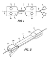
- the transducer according to the first embodiment has the form of an elongated transducer 1 of constant thickness made of a composite material, forming a strain gauge, comprising a central part 2 of constant section intended for the measurement of stresses, the two ends are integral with stress transmission parts 3, 4, shaped to connect this gauge to the structure whose stress is to be measured.
- Each of these stress transmission parts has a bulged part, connected to the central part 2 by radii of curvature R 1 , R 2 .
- These stress transmission parts 3, 4 which serve to transmit the stresses of the structure to the central part 2 each have two openings 5a, 5b respectively 6a, 6b occupying relative positions symmetrical with respect to the longitudinal axis of the elongated transducer 1 These openings are used for fixing the stress transmission parts 3, 4 to the structure to be checked, which must then be provided with pins capable of fitting into the openings 5a, 5b, 6a, 6b, screws which can allow ensure that the transducer is attached to the structure to be measured.
- An optical fiber 7 passes longitudinally through the elongated transducer 1. One of its ends is intended to be connected to a photoemitter 8 while the other is connected to a photoreceptor 9. Depending on the measuring device used, the light can be reflected, partially or totally, so that the photoemitter 8 and photoreceptor 9 can then be find, as illustrated by figure 1, at a same end of the optical fiber 7, this end of the fiber optic 7 then having the shape of a Y, 10 for allow the same end of the optical fiber to be connected 7 to the transmitter 8 and to the receiver 9, in a manner well known from the skilled person.
- the optical fiber segment 7 passing through the central part 2 of the transducer 1 of the gauge constraint presents, for example, a Bragg grating, intended to selectively reflect a wavelength determined, the latter varying as a function of the elongation of the optical fiber 7 subjected to the stress to be measured.
- the wavelength of the reflected light compared to that of incident light, determines the value of this constraint.
- Other light measurement principles could also be used, such as interferometry.
- the transducer 1 made of composite material according to the invention is formed by stacking sheets of a resin intended to constitute the matrix, in which are embedded in sheets of straight reinforcing filaments, arranged parallel to each other.
- the resin is PEEK and the reinforcing filaments are high modulus filaments, especially carbon filaments, aramid fibers, or even glass filaments.
- the choice of filaments and their proportion in the matrix depends on the modulus of elasticity desired for transducer 1.
- sheets are cut of PEEK armed with reinforcing filaments in the shape of transducer 1. Some of these sheets are cut so that the reinforcing filaments are arranged parallel to the longitudinal axis of the transducer 1, others with reinforcing filaments extending perpendicular to this longitudinal axis. According to one variant, the leaves could be cut to shape of the transducer after being stacked.
- optical fiber 7 along the axis longitudinal, i.e. well centered with respect to the width of the transducer, with its Bragg grating centered longitudinally with respect to the central part 2 of the transducer 1.
- a weight is attached to each end of this optical fiber 7 to ensure that it is well rectilinear, and we continue stacking the material sheets composite precut, by successively arranging, 3 sheets with 0 ° orientation, 1 sheet with 90 ° orientation, 2 sheets with 0 ° orientation, 1 sheet with 90 ° orientation and 1 sheet with 0 ° orientation.
- second sheet aluminum on the surface of which product is sprayed release agent, which can also be sprayed onto the surface of the upper part of the mold.
- the mold is then heated for 10 min at 400 ° C. and then tighten the screws with a moment of 4 N.m.
- the transducer 1 has a thickness of the order of 2.2 mm, a length of 120 mm, the length of the middle part 2 being 20 mm and its width of 5 mm, the radii R 1 and R 2 are 10 mm each and the width of the stress transmission parts 3, 4 is 24 mm.
- the composite used can also be a composite reinforced by a mixture of high modulus filaments elasticity of the aforementioned type and metal filaments, so as to allow the welding of the transducer on the structure to control.
- the components can be chosen entering into the composition of the composite material and their proportions so as to obtain a composite material whose thermal coefficient is close to zero, so to compensate for the effects of temperature variations which modify the behavior of the Bragg grating. This allows therefore to obtain a self-compensating transducer.
- the transducer according to the first embodiment illustrated in Figure 1 is more particularly intended to be fixed to the surface of a structure to be inspected in because of its constant thickness and the openings 5a, 5b, 6a, 6b intended to allow the transducer to be fixed to the structure to control.
- the second embodiment illustrated in Figure 2 is however studied more specifically to be able to be embedded in a structure, in particular in a structure concrete.
- the transducer 11 is of constant width
- the central part 12 of strain measurement is constituted by a blade
- the stress transmission parts 13, 14 are, in this case, thicker than the part central 12, the excess thickness being distributed substantially symmetrically on either side of the blade of the part Central.
- the internal transverse face 13a, respectively 14a of each stress transmission part 13, 14 forms an angle ⁇ between 6 ° and 30 °, preferably between 6 ° and 15 °.
- the optical fiber 7 passes substantially the along the longitudinal axis of transducer 11 and a network of Bragg is centered in the middle of the length of the part of strain measure 12.
- the transducer 11 is made of composite material reinforced with filaments high modulus of elasticity.
- the strain gauge has a length of 640 mm, the central part 12 having a length of 320 mm.
- the width of this transducer 11 is 80 mm.
- the thickness of the central part 12 is 2 to 2.5 mm and that of the transmission parts of constraints 13, 14, between 6 and 7 mm.
- this embodiment does not require the structure to be provided fixing means, since it suffices to drown the transducer in the structure to be checked.
- this advantage is practically limited to concrete structures under construction, whereas the first embodiment can be attached to any structure, as well as structures existing concrete.
- an optical fiber 7 passes through a transducer.
- the same fiber optics can include multiple length Bragg gratings different waves distributed at distances determined along this optical fiber, each of these networks being associated with a transducer 1 or 11, the signals reflected by each Bragg grating being multiplexed by the photoreceptor 9. Thanks to this arrangement, it is typically possible to measure signals from 10 to 20 transducers with the same measuring device and differentiate the results thanks to multiplexing, thus allowing to know the value of the stress recorded by each transducer. The number of transducers and the spacing between them can be adapted according to the structure to control.
- micro-bends it is very important to reduce to maximum losses induced by the communicated micro-bends to optical fiber.
- the matrix of transducer 1 or 11 is formed of coated parallel reinforcing continuous filament sheets of the matrix resin, the orientations of these filaments reinforcement being crossed at 90 ° angles.
- interferometry we measure the interference of light signals traveling two optical fibers, one subject to the the other to measure a reference optical fiber.
- the same transducer could still be crossed by two optical fibers arranged on either side neutral transducer fiber to measure compression using one of them and a pull with the other.
Landscapes
- Physics & Mathematics (AREA)
- General Physics & Mathematics (AREA)
- Length Measuring Devices By Optical Means (AREA)
- Optical Transform (AREA)
- Measurement Of Length, Angles, Or The Like Using Electric Or Magnetic Means (AREA)
- Gas-Insulated Switchgears (AREA)
- Light Guides In General And Applications Therefor (AREA)
Description
Claims (10)
- Dispositif à fibre optique pour la mesure de contraintes, comprenant au moins un transducteur (1; 11) formé d'une matrice traversée par au moins un segment de fibre optique (7) conformée pour que la transmission de lumière soit modifiée en fonction d'une contrainte à mesurer, transmise par ladite matrice à ladite fibre optique (7), une extrémité d'entrée de cette fibre optique (7) étant destinée à être reliée à un photoémetteur (8) et une extrémité de sortie à un photorécepteur (9), caractérisé en ce que ledit transducteur (1; 11) est de forme allongée, traversé longitudinalement par ledit segment de fibre optique (7) et qu'il comprend un tronçon médian (2; 12) destiné à être soumis aux contraintes à mesurer, ses deux extrémités étant solidaires respectivement de deux parties de transmission des contraintes (3, 4; 13, 14) audit tronçon médian (2; 12), présentant des moyens (5a, 5b, 6a, 6b; 13a, 14a) pour les rendre solidaires de la structure à mesurer et en ce que ladite matrice est en un matériau composite renforcé de filaments pour donner audit transducteur (1; 11) un module d'élasticité qui peut être adapté en fonction de la structure à mesurer.
- Dispositif selon la revendication 1, caractérisé en ce que ledit transducteur (1) est d'épaisseur sensiblement constante, ladite fibre optique (7) traversant ce transducteur (1; 11) sensiblement au milieu de son épaisseur et de sa largeur.
- Dispositif selon l'une des revendications précédentes, caractérisé en ce que lesdits filaments de renfort sont des filaments à haut module d'élasticité.
- Dispositif selon l'une des revendications précédentes, caractérisé en ce que lesdits filaments de renfort sont réparties sous forme de couches de filaments parallèles tantôt orientées longitudinalement tantôt transversalement audit transducteur.
- Dispositif selon la revendication 4, caractérisé en ce que les couches de matériau composites adjacentes à ladite fibre optique (7) présentent des filaments de renfort orientés parallèlement à cette fibre optique (7) et que le nombre ou de couches successives ou l'épaisseur de celles-ci dans lesquelles les filaments de renfort sont orientés parallèlement à cette fibre optique (7) augmente au fur et à mesure que l'on se rapproche de ladite fibre optique (7).
- Dispositif selon l'une des revendications précédentes, caractérisé en ce que lesdits moyens pour modifier la transmission de lumière à travers ladite fibre optique sont formés par un réseau de Bragg.
- Dispositif selon la revendication 6, caractérisé en ce que le coefficient thermique de ladite matrice est choisi voisin de zéro afin de compenser les effets des variations de température sur le réseau de Bragg.
- Dispositif selon l'une des revendications précédentes, caractérisé en ce que du métal est incorporé à ladite matrice au voisinage d'au moins une de ses faces externes, pour permettre de souder ledit transducteur (1; 11) à une structure métallique.
- Dispositif selon l'une des revendications 1, 3 à 8, caractérisé en ce que lesdites parties de transmission des contraintes (13, 14) présentent chacune deux surépaisseurs de part et d'autre d'une lame (12) s'étendant sur toute la longueur dudit transducteur (11), la face transversale (13a, 14a) interne de chaque surépaisseur formant un angle () compris entre 6° et 30° avec les faces respectives de ladite lame (12).
- Dispositif selon l'une des revendications précédentes, caractérisé en ce qu'une pluralité de transducteurs sont associé à une même fibre optique, les segments respectifs de la fibre associés à ladite pluralité de transducteurs présentant chacun un réseau de Bragg réfléchissant une longueur d'onde différente, ledit photorécepteur (9) comportant des moyens de multiplexage des signaux réfléchis.
Priority Applications (3)
| Application Number | Priority Date | Filing Date | Title |
|---|---|---|---|
| DE69820050T DE69820050D1 (de) | 1998-09-04 | 1998-09-04 | Lichtwellenleiterverformungssensor |
| AT98402198T ATE255219T1 (de) | 1998-09-04 | 1998-09-04 | Lichtwellenleiterverformungssensor |
| EP98402198A EP0984243B1 (fr) | 1998-09-04 | 1998-09-04 | Dispositif à fibre optique pour la mesure de contraintes |
Applications Claiming Priority (1)
| Application Number | Priority Date | Filing Date | Title |
|---|---|---|---|
| EP98402198A EP0984243B1 (fr) | 1998-09-04 | 1998-09-04 | Dispositif à fibre optique pour la mesure de contraintes |
Publications (2)
| Publication Number | Publication Date |
|---|---|
| EP0984243A1 EP0984243A1 (fr) | 2000-03-08 |
| EP0984243B1 true EP0984243B1 (fr) | 2003-11-26 |
Family
ID=8235482
Family Applications (1)
| Application Number | Title | Priority Date | Filing Date |
|---|---|---|---|
| EP98402198A Expired - Lifetime EP0984243B1 (fr) | 1998-09-04 | 1998-09-04 | Dispositif à fibre optique pour la mesure de contraintes |
Country Status (3)
| Country | Link |
|---|---|
| EP (1) | EP0984243B1 (fr) |
| AT (1) | ATE255219T1 (fr) |
| DE (1) | DE69820050D1 (fr) |
Cited By (2)
| Publication number | Priority date | Publication date | Assignee | Title |
|---|---|---|---|---|
| DE102006059439A1 (de) * | 2006-12-15 | 2008-06-19 | Prüftechnik Dieter Busch AG | Verfahren und Vorrichtung zur dynamischen Messung der axialen Deformation einer rotierenden Hohlwelle |
| RU2799986C1 (ru) * | 2022-11-16 | 2023-07-14 | федеральное государственное автономное образовательное учреждение высшего образования "Пермский национальный исследовательский политехнический университет" | Волоконно-оптический датчик механических напряжений |
Families Citing this family (10)
| Publication number | Priority date | Publication date | Assignee | Title |
|---|---|---|---|---|
| WO2001067038A1 (fr) * | 1998-09-04 | 2001-09-13 | Fiber Optic Sensors-Fos Sa | Dispositif a fibre optique pour la mesure de contraintes |
| CN100340839C (zh) * | 2005-09-27 | 2007-10-03 | 天津大学 | 光纤应变测量仪及其测量方法 |
| EP2122161B2 (fr) | 2007-02-19 | 2024-01-17 | Vestas Wind Systems A/S | Pale d'éolienne dotée d'un moyen de détection de contrainte, éolienne, unité capteur et leurs utilisations |
| EP2260281B1 (fr) | 2008-03-31 | 2017-05-03 | Vestas Wind Systems A/S | Capteur de déformation à transmission optique pour éoliennes |
| GB2461532A (en) | 2008-07-01 | 2010-01-06 | Vestas Wind Sys As | Sensor system and method for detecting deformation in a wind turbine component |
| GB2461566A (en) | 2008-07-03 | 2010-01-06 | Vestas Wind Sys As | Embedded fibre optic sensor for mounting on wind turbine components and method of producing the same. |
| GB2466433B (en) | 2008-12-16 | 2011-05-25 | Vestas Wind Sys As | Turbulence sensor and blade condition sensor system |
| GB2472437A (en) | 2009-08-06 | 2011-02-09 | Vestas Wind Sys As | Wind turbine rotor blade control based on detecting turbulence |
| GB2477529A (en) | 2010-02-04 | 2011-08-10 | Vestas Wind Sys As | A wind turbine optical wind sensor for determining wind speed and direction |
| DE102016011610B3 (de) * | 2016-09-26 | 2018-08-09 | Hottinger Baldwin Messtechnik Gmbh | Anschweißbarer Dehnungssensor für gekrümmte Oberflächen |
Family Cites Families (3)
| Publication number | Priority date | Publication date | Assignee | Title |
|---|---|---|---|---|
| US4636638A (en) * | 1984-10-12 | 1987-01-13 | The United States Of America As Represented By The Secretary Of The Navy | Remote optical crack sensing system including fiberoptics |
| US5649035A (en) * | 1995-11-03 | 1997-07-15 | Simula Inc. | Fiber optic strain gauge patch |
| US5770155A (en) * | 1995-11-21 | 1998-06-23 | United Technologies Corporation | Composite structure resin cure monitoring apparatus using an optical fiber grating sensor |
-
1998
- 1998-09-04 AT AT98402198T patent/ATE255219T1/de not_active IP Right Cessation
- 1998-09-04 DE DE69820050T patent/DE69820050D1/de not_active Expired - Lifetime
- 1998-09-04 EP EP98402198A patent/EP0984243B1/fr not_active Expired - Lifetime
Cited By (3)
| Publication number | Priority date | Publication date | Assignee | Title |
|---|---|---|---|---|
| DE102006059439A1 (de) * | 2006-12-15 | 2008-06-19 | Prüftechnik Dieter Busch AG | Verfahren und Vorrichtung zur dynamischen Messung der axialen Deformation einer rotierenden Hohlwelle |
| DE102006059439B4 (de) * | 2006-12-15 | 2018-01-25 | Prüftechnik Dieter Busch AG | Verfahren und Vorrichtung zur dynamischen Messung der axialen Deformation einer rotierenden Hohlwelle |
| RU2799986C1 (ru) * | 2022-11-16 | 2023-07-14 | федеральное государственное автономное образовательное учреждение высшего образования "Пермский национальный исследовательский политехнический университет" | Волоконно-оптический датчик механических напряжений |
Also Published As
| Publication number | Publication date |
|---|---|
| ATE255219T1 (de) | 2003-12-15 |
| EP0984243A1 (fr) | 2000-03-08 |
| DE69820050D1 (de) | 2004-01-08 |
Similar Documents
| Publication | Publication Date | Title |
|---|---|---|
| CA2402675A1 (fr) | Dispositif a fibre optique pour la mesure de contraintes | |
| KR100215950B1 (ko) | 단일 회절 격자를 이용하여 변형 및 온도를 측정할 수 있는 삽입된 광센서 | |
| US5633748A (en) | Fiber optic Bragg grating demodulator and sensor incorporating same | |
| FR2557293A1 (fr) | Capteur de pression optique a compensation de temperature | |
| EP1620697A2 (fr) | Dispositif, systeme et procede de mesure de deformations mecaniques et/ou thermiques uniaxiales au moyen d une fibre optique a reseau de bragg | |
| EP1114300B1 (fr) | Capteur de temperature a fibre optique | |
| EP0365062B1 (fr) | Capteur de pression à fibre optique | |
| EP0984243A1 (fr) | Dispositif à fibre optique pour la mesure de contraintes | |
| EP0034181A1 (fr) | Jauge de contrainte a fibre optique. | |
| FR2700021A1 (fr) | Appareil de libération des contraintes d'une fibre optique. | |
| EP0033048A1 (fr) | Interféromètre à cavité optique accordable comprenant une fibre optique monomode et application au filtrage et à la spectrographie | |
| FR2826448A1 (fr) | Systeme de mesure differentielle fonde sur l'utilisation de paires de reseaux de bragg | |
| FR2487083A1 (fr) | Dispositif a fibre optique pour la transmission de lumiere a polarisation lineaire | |
| EP0360759B1 (fr) | Capeur de force à guide d'ondes optique intégré dans un substrat | |
| FR2641861A1 (fr) | Dispositif de mesure opto-electronique | |
| EP3274670B1 (fr) | Procédé de fabrication d'un dispositif de capteur à fibre optique | |
| EP3433575B1 (fr) | Capteur de courbure a fibre optique et dispositif de mesure comprenant ledit capteur | |
| JP2005134199A (ja) | ファイバ型センサ及びそれを用いたセンシングシステム | |
| WO2023007104A1 (fr) | Dispositif de mesure de pression hydrostatique, notamment absolue et/ou de température et procédé de mesure associé | |
| EP1588124B1 (fr) | Extensometre a corps d'epreuve flexible et reseaux de bragg | |
| WO2001067038A1 (fr) | Dispositif a fibre optique pour la mesure de contraintes | |
| EP3948168B1 (fr) | Dispositif de répartition de signal pour la mesure de décalages en longueur d'onde | |
| EP0943906B1 (fr) | Capteur d'effort à fibre optique, procédé de fabrication d'un tel capteur, et dispositif de détection d'effort utilisant ce capteur | |
| EP0502781A1 (fr) | Capteur optique, en particulier capteur de pression et procédé de mesure optique correspondant | |
| EP0503985B1 (fr) | Capteur de force et appareillage pour capter le courant d'une ligne caténaire depuis une motrice utilisant ce capteur |
Legal Events
| Date | Code | Title | Description |
|---|---|---|---|
| PUAI | Public reference made under article 153(3) epc to a published international application that has entered the european phase |
Free format text: ORIGINAL CODE: 0009012 |
|
| AK | Designated contracting states |
Kind code of ref document: A1 Designated state(s): AT BE CH DE DK ES FI FR GB IE IT LI NL SE |
|
| AX | Request for extension of the european patent |
Free format text: AL;LT;LV;MK;RO;SI |
|
| 17P | Request for examination filed |
Effective date: 20000904 |
|
| AKX | Designation fees paid |
Free format text: AT BE CH DE DK ES FI FR GB IE IT LI NL SE |
|
| RAP1 | Party data changed (applicant data changed or rights of an application transferred) |
Owner name: FIBER OPTIC SENSORS- FOS SA |
|
| GRAH | Despatch of communication of intention to grant a patent |
Free format text: ORIGINAL CODE: EPIDOS IGRA |
|
| GRAS | Grant fee paid |
Free format text: ORIGINAL CODE: EPIDOSNIGR3 |
|
| GRAA | (expected) grant |
Free format text: ORIGINAL CODE: 0009210 |
|
| AK | Designated contracting states |
Kind code of ref document: B1 Designated state(s): AT BE CH DE DK ES FI FR GB IE IT LI NL SE |
|
| PG25 | Lapsed in a contracting state [announced via postgrant information from national office to epo] |
Ref country code: NL Free format text: LAPSE BECAUSE OF FAILURE TO SUBMIT A TRANSLATION OF THE DESCRIPTION OR TO PAY THE FEE WITHIN THE PRESCRIBED TIME-LIMIT Effective date: 20031126 Ref country code: IT Free format text: LAPSE BECAUSE OF FAILURE TO SUBMIT A TRANSLATION OF THE DESCRIPTION OR TO PAY THE FEE WITHIN THE PRESCRIBED TIME-LIMIT;WARNING: LAPSES OF ITALIAN PATENTS WITH EFFECTIVE DATE BEFORE 2007 MAY HAVE OCCURRED AT ANY TIME BEFORE 2007. THE CORRECT EFFECTIVE DATE MAY BE DIFFERENT FROM THE ONE RECORDED. Effective date: 20031126 Ref country code: IE Free format text: LAPSE BECAUSE OF FAILURE TO SUBMIT A TRANSLATION OF THE DESCRIPTION OR TO PAY THE FEE WITHIN THE PRESCRIBED TIME-LIMIT Effective date: 20031126 Ref country code: GB Free format text: LAPSE BECAUSE OF FAILURE TO SUBMIT A TRANSLATION OF THE DESCRIPTION OR TO PAY THE FEE WITHIN THE PRESCRIBED TIME-LIMIT Effective date: 20031126 Ref country code: FI Free format text: LAPSE BECAUSE OF FAILURE TO SUBMIT A TRANSLATION OF THE DESCRIPTION OR TO PAY THE FEE WITHIN THE PRESCRIBED TIME-LIMIT Effective date: 20031126 Ref country code: AT Free format text: LAPSE BECAUSE OF FAILURE TO SUBMIT A TRANSLATION OF THE DESCRIPTION OR TO PAY THE FEE WITHIN THE PRESCRIBED TIME-LIMIT Effective date: 20031126 |
|
| REG | Reference to a national code |
Ref country code: GB Ref legal event code: FG4D Free format text: NOT ENGLISH |
|
| REG | Reference to a national code |
Ref country code: CH Ref legal event code: EP |
|
| REF | Corresponds to: |
Ref document number: 69820050 Country of ref document: DE Date of ref document: 20040108 Kind code of ref document: P |
|
| REG | Reference to a national code |
Ref country code: IE Ref legal event code: FG4D Free format text: FRENCH |
|
| PG25 | Lapsed in a contracting state [announced via postgrant information from national office to epo] |
Ref country code: SE Free format text: LAPSE BECAUSE OF FAILURE TO SUBMIT A TRANSLATION OF THE DESCRIPTION OR TO PAY THE FEE WITHIN THE PRESCRIBED TIME-LIMIT Effective date: 20040226 Ref country code: DK Free format text: LAPSE BECAUSE OF FAILURE TO SUBMIT A TRANSLATION OF THE DESCRIPTION OR TO PAY THE FEE WITHIN THE PRESCRIBED TIME-LIMIT Effective date: 20040226 |
|
| PG25 | Lapsed in a contracting state [announced via postgrant information from national office to epo] |
Ref country code: DE Free format text: LAPSE BECAUSE OF FAILURE TO SUBMIT A TRANSLATION OF THE DESCRIPTION OR TO PAY THE FEE WITHIN THE PRESCRIBED TIME-LIMIT Effective date: 20040227 |
|
| PG25 | Lapsed in a contracting state [announced via postgrant information from national office to epo] |
Ref country code: ES Free format text: LAPSE BECAUSE OF FAILURE TO SUBMIT A TRANSLATION OF THE DESCRIPTION OR TO PAY THE FEE WITHIN THE PRESCRIBED TIME-LIMIT Effective date: 20040309 |
|
| NLV1 | Nl: lapsed or annulled due to failure to fulfill the requirements of art. 29p and 29m of the patents act | ||
| GBV | Gb: ep patent (uk) treated as always having been void in accordance with gb section 77(7)/1977 [no translation filed] |
Effective date: 20031126 |
|
| REG | Reference to a national code |
Ref country code: IE Ref legal event code: FD4D |
|
| PG25 | Lapsed in a contracting state [announced via postgrant information from national office to epo] |
Ref country code: LI Free format text: LAPSE BECAUSE OF NON-PAYMENT OF DUE FEES Effective date: 20040930 Ref country code: CH Free format text: LAPSE BECAUSE OF NON-PAYMENT OF DUE FEES Effective date: 20040930 Ref country code: BE Free format text: LAPSE BECAUSE OF NON-PAYMENT OF DUE FEES Effective date: 20040930 |
|
| PLBE | No opposition filed within time limit |
Free format text: ORIGINAL CODE: 0009261 |
|
| STAA | Information on the status of an ep patent application or granted ep patent |
Free format text: STATUS: NO OPPOSITION FILED WITHIN TIME LIMIT |
|
| 26N | No opposition filed |
Effective date: 20040827 |
|
| REG | Reference to a national code |
Ref country code: CH Ref legal event code: PFA Owner name: FOS SA Free format text: FIBER OPTIC SENSORS- FOS SA#12, AVENUE DES MORGINES#1213 PETIT-LANCY (CH) -TRANSFER TO- FOS SA#RUE DE BERNE 9#1201 GENEVE (CH) |
|
| BERE | Be: lapsed |
Owner name: S.A. FIBER OPTIC SENSORS- *FOS Effective date: 20040930 |
|
| REG | Reference to a national code |
Ref country code: CH Ref legal event code: PL |
|
| PG25 | Lapsed in a contracting state [announced via postgrant information from national office to epo] |
Ref country code: FR Free format text: LAPSE BECAUSE OF NON-PAYMENT OF DUE FEES Effective date: 20050531 |
|
| REG | Reference to a national code |
Ref country code: FR Ref legal event code: ST |
|
| BERE | Be: lapsed |
Owner name: S.A. FIBER OPTIC SENSORS- *FOS Effective date: 20040930 |