EP0984221A2 - Beleuchtungs-Steuereinrichtung - Google Patents
Beleuchtungs-Steuereinrichtung Download PDFInfo
- Publication number
- EP0984221A2 EP0984221A2 EP99306660A EP99306660A EP0984221A2 EP 0984221 A2 EP0984221 A2 EP 0984221A2 EP 99306660 A EP99306660 A EP 99306660A EP 99306660 A EP99306660 A EP 99306660A EP 0984221 A2 EP0984221 A2 EP 0984221A2
- Authority
- EP
- European Patent Office
- Prior art keywords
- mirrors
- light
- control apparatus
- lighting control
- beams
- Prior art date
- Legal status (The legal status is an assumption and is not a legal conclusion. Google has not performed a legal analysis and makes no representation as to the accuracy of the status listed.)
- Withdrawn
Links
- 230000001419 dependent effect Effects 0.000 claims 1
- 230000000694 effects Effects 0.000 description 28
- 240000005528 Arctium lappa Species 0.000 description 9
- 239000003086 colorant Substances 0.000 description 5
- 238000011161 development Methods 0.000 description 4
- 230000018109 developmental process Effects 0.000 description 4
- 230000015572 biosynthetic process Effects 0.000 description 2
- 238000009987 spinning Methods 0.000 description 2
- BQCADISMDOOEFD-UHFFFAOYSA-N Silver Chemical compound [Ag] BQCADISMDOOEFD-UHFFFAOYSA-N 0.000 description 1
- 230000004913 activation Effects 0.000 description 1
- 238000009434 installation Methods 0.000 description 1
- 230000001795 light effect Effects 0.000 description 1
- 229910001507 metal halide Inorganic materials 0.000 description 1
- 150000005309 metal halides Chemical class 0.000 description 1
- 238000000034 method Methods 0.000 description 1
- 230000000135 prohibitive effect Effects 0.000 description 1
- 229910052709 silver Inorganic materials 0.000 description 1
- 239000004332 silver Substances 0.000 description 1
- 239000000779 smoke Substances 0.000 description 1
- 230000002311 subsequent effect Effects 0.000 description 1
Images

Classifications
-
- F—MECHANICAL ENGINEERING; LIGHTING; HEATING; WEAPONS; BLASTING
- F21—LIGHTING
- F21S—NON-PORTABLE LIGHTING DEVICES; SYSTEMS THEREOF; VEHICLE LIGHTING DEVICES SPECIALLY ADAPTED FOR VEHICLE EXTERIORS
- F21S10/00—Lighting devices or systems producing a varying lighting effect
- F21S10/04—Lighting devices or systems producing a varying lighting effect simulating flames
-
- F—MECHANICAL ENGINEERING; LIGHTING; HEATING; WEAPONS; BLASTING
- F21—LIGHTING
- F21S—NON-PORTABLE LIGHTING DEVICES; SYSTEMS THEREOF; VEHICLE LIGHTING DEVICES SPECIALLY ADAPTED FOR VEHICLE EXTERIORS
- F21S10/00—Lighting devices or systems producing a varying lighting effect
- F21S10/06—Lighting devices or systems producing a varying lighting effect flashing, e.g. with rotating reflector or light source
-
- F—MECHANICAL ENGINEERING; LIGHTING; HEATING; WEAPONS; BLASTING
- F21—LIGHTING
- F21W—INDEXING SCHEME ASSOCIATED WITH SUBCLASSES F21K, F21L, F21S and F21V, RELATING TO USES OR APPLICATIONS OF LIGHTING DEVICES OR SYSTEMS
- F21W2131/00—Use or application of lighting devices or systems not provided for in codes F21W2102/00-F21W2121/00
- F21W2131/40—Lighting for industrial, commercial, recreational or military use
- F21W2131/406—Lighting for industrial, commercial, recreational or military use for theatres, stages or film studios
Definitions
- This invention relates to lighting control apparatus. More particularly but not exclusively this invention relates to a lighting control system for special effect lighting.
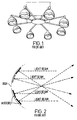
- the 'helicopter' comprised a number of pin spot lights arranged around a centre piece, as indicated in Figure 1.
- the separate lamps of the helicopter are manually adjustable to be angled and rotated using a motor until the desired effect is achieved. Typically this is a circular pattern of light pools rotating about the centre axis of the helicopter.
- the provision of individually adjustable lamp heads allows the helicopter to be used with different ceiling heights. In other words, the angles of the lamp heads may be pre-set to give a desired diameter of the circular light pattern, regardless of the height of the ceiling to which the helicopter is secured.
- the movement of lighting arrangements such as the helicopter is usually controlled by a lighting engineer or disc jockey ("DJ").
- the pin spot has been replaced by the 'flower effect' light
- the principle of the flower effect was to invert the principle of the mirrored ball.
- a plurality of coloured mirrored pieces are arranged on the concave surface of a dish. When light is directed onto this surface the beams of light from the mirrors converge to a common point which is then passed through a lens. After converging the beams would then continue into a flower pattern. This is indicated in figure 2.
- the 'flower effect' light is controllable in terms of sound activation and rotation.
- DMX digital language
- One of the most recent advances includes the ability to project a large number of beams from one source in the colour and shape of a DJ's choice and move them in time to music.
- This advance uses a combination of the 'flower effect' dish and the separately selectable colours and shapes described above. It is achieved by fitting a plurality of silver mirrored pieces to the concave surface of a dish and the passing the reflected beams of light through a selection of colours and GOBO's mounted on a motorised wheel. The motors are controlled by the above mentioned DMX control system.
- the 'helicopter' effect employs a brush gear which tends to wear quickly. Also it is extremely difficult to change the colours of each individual lamp of the helicopter whilst in operation. Such changes in colour had to be provided during non-operation of the helicopter.
- the standard helicopter was capable of little control (i.e. of lighting colour and shapes) once in operation, other than turning it off and on.
- the helicopter is the only system which produces a 'carousel' lighting effect which is capable of beam angle adjustment, albeit manual adjustment.
- the "carousel” effect is the rotation of all the lights around a centrepoint.
- lighting control apparatus comprising a plurality of mirrors positioned so as to receive at least one beam of light said mirrors being independently moveable such that the angle of a beam of light reflected from each mirror is adjustable wherein each of said mirrors is mounted on a support structure said support structure being rotatable about a substantially central axis such that the beams of light reflected from the mirrors are adapted to simultaneously rotate about said substantially central axis.
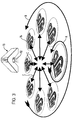
- a beam of light from a light source is rotated and formed into a desired shape, then split into a number of beams by the mirrors thus producing a carousel effect of lights spinning in unison.
- lighting control apparatus comprising a plurality of mirrors positioned to receive at least one beam of light, said mirrors being mounted on a support structure, said support structure being rotatable; and means for providing rotation to said at least one beam of light wherein said beam of light is dividable into a plurality of beams of light upon reflection by said mirrors each of said reflected beams being adapted to simultaneously rotate about a common axis.
- the mirrors are individually adjustable in terms of angle and also capable of rotating around a common axis thus producing a carousel effect of lights which are adjustable in terms of beam pitch.
- lighting control apparatus shown generally at 10 produces a plurality of beams 12. Each beam produces a spotlight 14 that may comprise any shape, design or colour.
- a light source 16 such as a metal halide lamp is positioned within a reflector 18 which directs light onto a condenser lens 20.
- the condenser lens aligns the rays of light forming the beam produced from the light source.
- the condenser may not be required if the beam of light produced from the light source is of a high quality in terms of focus.
- This light is then directed through a colour filter 22 mounted on a colour wheel 24.
- the colour wheel comprises a number of different colour filters and is rotatable so as to provide a predetermined colour through which the light is directed. Rotation of colour wheel 24 occurs through use of motor 26.
- the rotary output shaft of motor 26 is secured to the centre of colour wheel 22.
- a beam of light 28, having passed through the filter 22 of the colour wheel 24 is then directed through a shutter 30 which may be operated at various speeds to provide a flashing light effect.
- the shutter is operated by motor 32.
- the rotary output shaft of motor 32 is secured to a shutter plate that may, as a result of operation of motor 32, be repeatedly interposed into the light beam.
- the speed of rotation of motor 32 dictates the rate of flashing
- the beam of light 28 is then directed through a GOBO plate 34 or any suitable means such as a photographic slide for providing the beam of light with a desired shape.
- a preferred form of GOBO is a shape cut out of a plate through which light is then directed, the emerging beam of light then being formed in the shape of the GOBO.
- the GOBO plate is also operable through use of rotary motor 36 so as to rotate the pattern thus defined in the beam of light 28.
- the emerging beam of light 38 is then directed through a focus lens 40.
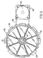
- each mirror 44 has the shape of a triangle truncated adjacent its apex ( Figure 5). Other mirror shapes are possible.
- Each mirror 44 is mounted on an adjustable plate 46 which is itself mounted on a central support member 48.
- the mirrors are arranged to be generally adjacent one another such that a substantially concave or convex formation of mirrors is provided. The formation is adjustable between convex and concave shapes. A concave shape is clearly shown in Figure 5.
- the beam of light is split by the mirrors into a number of beams of light, corresponding to the number of mirrors 44 reflecting light.
- Each mirror reflects an individual beam of light corresponding to the shape and colour previously selected by the gobo and colour filter.
- the plates 46 are flexibly mounted at their radially inner ends on the central support member 48 through springs 50.
- This flexible mounting arrangement allows the mirrors to be individually adjusted to alter the angle of the beam reflected.
- This flexible mounting allows the mirrors to be tilted about one of their ends thus producing a concave (as shown), flat or convex array of mirrors.
- the support member 48 includes a central, threaded bore mounted on a screw 52.
- a rotary motor 54 is selectively operable to rotate the screw 52. Rotation of the screw 52 is enabled by its attachment to a spindle 56 mounted within a journal bearing 58 and attached to motor 54. Through operation of the motor 54 to rotate the screw 52 the angle of the mirrors may be remotely adjusted.
- the mirrors 44 and associated mounting apparatus are housed within a casing in the form of a dish or cup 64.
- cup 64 is in a preferred embodiments octagonal in plan view, although other shapes are of course possible.
- One end 45 of each mirror plate 46 is mounted within a sliding joint 68 formed in the cup 64.
- Each sliding joint takes the form of an aperture in the upstanding wall 64' of cup 64.
- a flat tab 46' protrudes from the radially outer edge of each plate 46 and is slidably received in the aperture, providing a radially slideable mounting for the plate 46.
- This sliding joint ensures that the mirrors 44 are located in a desired position and the adjustment of their mounting angle via rotation of the screw 52 is smoothly effected.
- Pulleys 60 and 60' and associated drive belt 62 are provided to allow rotary movement of the entire cup 64 and hence the beams reflected form the mirrors 44.
- a further rotary motor 66 whose output shaft is secured to the centre of pulley 60' provides rotating movement to the carousel cup 64 as also shown in Figure 5.
- this lighting arrangement provides the circular carousel movement of the prior art 'helicopter' without the need for individually adjustable lamps.
- the rotatable gobo wheel 34 and the rotatable colour wheel 24 also provide the beam of light 38 with a choice of colour and shape.
- the beams 42 reflected by the mirrors 44 therefore also have colours and shapes corresponding to the colour and shape of beam 38. They are also rotatable around both their own axis as shown in Figure 3 by arrow A and also about a common axis as indicated by arrow B.
- the angle at which the beams 42 are reflected from mirrors 44 is also adjustable to allow for different ceiling heights thus providing variable beam pitch and an added lighting effect of varying the pitch of the beams whilst in operation.
- This variation in pitch angle is shown in Figure 3 by arrows C.
- the apparatus of the invention may be controlled e.g. by an electronic controller that sends control pulses to each of the motors, using the above-mentioned DMX language.
- Each motor may be permanently connected to a current source, and the DMX control pulses may be used to switch the motors on and off individually, according to encoded information contained within the DMX pulses.
Landscapes
- Engineering & Computer Science (AREA)
- General Engineering & Computer Science (AREA)
- Non-Portable Lighting Devices Or Systems Thereof (AREA)
- Lighting Device Outwards From Vehicle And Optical Signal (AREA)
Applications Claiming Priority (2)
| Application Number | Priority Date | Filing Date | Title |
|---|---|---|---|
| GB9818853A GB2341113B (en) | 1998-08-29 | 1998-08-29 | Apparatus for controlling light |
| GB9818853 | 1998-08-29 |
Publications (2)
| Publication Number | Publication Date |
|---|---|
| EP0984221A2 true EP0984221A2 (de) | 2000-03-08 |
| EP0984221A3 EP0984221A3 (de) | 2002-06-12 |
Family
ID=10838035
Family Applications (1)
| Application Number | Title | Priority Date | Filing Date |
|---|---|---|---|
| EP99306660A Withdrawn EP0984221A3 (de) | 1998-08-29 | 1999-08-23 | Beleuchtungs-Steuereinrichtung |
Country Status (2)
| Country | Link |
|---|---|
| EP (1) | EP0984221A3 (de) |
| GB (1) | GB2341113B (de) |
Cited By (1)
| Publication number | Priority date | Publication date | Assignee | Title |
|---|---|---|---|---|
| CN100386568C (zh) * | 2004-04-09 | 2008-05-07 | 陈晓亮 | 用于电壁炉中的燃烧火焰仿真模拟方法及其专用装置 |
Family Cites Families (4)
| Publication number | Priority date | Publication date | Assignee | Title |
|---|---|---|---|---|
| GB952059A (en) * | 1959-03-20 | 1964-03-11 | Aaron Isaac Cohen | Producing optical effects |
| US4729071A (en) * | 1986-11-03 | 1988-03-01 | Altman Stage Lighting Co. | Low-inertial beam direction lighting system |
| JPH07296613A (ja) * | 1994-04-28 | 1995-11-10 | Pineda Sanchago Camiro Bonilla | 回転表示灯 |
| IT241021Y1 (it) * | 1996-11-22 | 2001-04-20 | Light Studio Di Mestrangelo Gi | Corpo illuminante per la riflessione di vari fasci luminosi |
-
1998
- 1998-08-29 GB GB9818853A patent/GB2341113B/en not_active Expired - Fee Related
-
1999
- 1999-08-23 EP EP99306660A patent/EP0984221A3/de not_active Withdrawn
Non-Patent Citations (1)
| Title |
|---|
| None |
Cited By (1)
| Publication number | Priority date | Publication date | Assignee | Title |
|---|---|---|---|---|
| CN100386568C (zh) * | 2004-04-09 | 2008-05-07 | 陈晓亮 | 用于电壁炉中的燃烧火焰仿真模拟方法及其专用装置 |
Also Published As
| Publication number | Publication date |
|---|---|
| GB9818853D0 (en) | 1998-10-21 |
| GB2341113B (en) | 2001-07-11 |
| GB2341113A (en) | 2000-03-08 |
| EP0984221A3 (de) | 2002-06-12 |
Similar Documents
| Publication | Publication Date | Title |
|---|---|---|
| EP0346432B1 (de) | Bühnenbeleuchtung mit veränderlicher strahlbreite | |
| US4729071A (en) | Low-inertial beam direction lighting system | |
| US9206962B2 (en) | Light effect system with rotatable light forming device | |
| US5951139A (en) | Surgical light with reflector-lamps and flat reflector panels | |
| EP0291475B1 (de) | Scheinwerfer für Kraftfahrzeuge mit programmierbarer Lichtverteilung | |
| US4400765A (en) | Operating room light fixture with adjustable light pattern | |
| EP0060068A1 (de) | Ferngesteuertes Beleuchtungssystem | |
| KR940001584B1 (ko) | 가변색상 조명장치 | |
| US4777568A (en) | Low-inertial beam direction lighting system | |
| EP0472718B1 (de) | Optisches system für beleuchtungsarmatur | |
| US6582092B1 (en) | Lamp for forming a low-shadow lighting field | |
| US11959630B2 (en) | Lighting device with motorised collimation control | |
| US5067064A (en) | Pattern change mechanism | |
| WO1991002666A1 (en) | Vehicular headlight | |
| US5915823A (en) | Central source light distribution system and components for maintaining beam continuity to adjustably positionable remote illumination directors | |
| EP0984221A2 (de) | Beleuchtungs-Steuereinrichtung | |
| EP1844262B1 (de) | Optisches system für ein washlight | |
| EP1075624B1 (de) | Vorrichtung zur strahlsteuerung | |
| US11149922B1 (en) | Light output reducing shutter system | |
| GB2342466A (en) | Light projector | |
| EP1236194B1 (de) | Verstellbares, dreidimensionales und mehrfarbiges wellengeneratorsystem | |
| AU628036B2 (en) | Variable beamwidth stage light | |
| JPH0215454Y2 (de) | ||
| CN103109128B (zh) | 具有分束效果的照明装置 | |
| GB2353726A (en) | Portable laser projector |
Legal Events
| Date | Code | Title | Description |
|---|---|---|---|
| PUAI | Public reference made under article 153(3) epc to a published international application that has entered the european phase |
Free format text: ORIGINAL CODE: 0009012 |
|
| AK | Designated contracting states |
Kind code of ref document: A2 Designated state(s): AT BE CH CY DE DK ES FI FR GB GR IE IT LI LU MC NL PT SE |
|
| AX | Request for extension of the european patent |
Free format text: AL;LT;LV;MK;RO;SI |
|
| PUAL | Search report despatched |
Free format text: ORIGINAL CODE: 0009013 |
|
| AK | Designated contracting states |
Kind code of ref document: A3 Designated state(s): AT BE CH CY DE DK ES FI FR GB GR IE IT LI LU MC NL PT SE |
|
| AX | Request for extension of the european patent |
Free format text: AL;LT;LV;MK;RO;SI |
|
| AKX | Designation fees paid |
Designated state(s): AT BE CH CY DE DK ES FI FR GB GR IE IT LI LU MC NL PT SE |
|
| STAA | Information on the status of an ep patent application or granted ep patent |
Free format text: STATUS: THE APPLICATION IS DEEMED TO BE WITHDRAWN |
|
| 18D | Application deemed to be withdrawn |
Effective date: 20021213 |