EP0983894A2 - Vehicle speed control using engine and brake systems to achieve target acceleration - Google Patents
Vehicle speed control using engine and brake systems to achieve target acceleration Download PDFInfo
- Publication number
- EP0983894A2 EP0983894A2 EP99306948A EP99306948A EP0983894A2 EP 0983894 A2 EP0983894 A2 EP 0983894A2 EP 99306948 A EP99306948 A EP 99306948A EP 99306948 A EP99306948 A EP 99306948A EP 0983894 A2 EP0983894 A2 EP 0983894A2
- Authority
- EP
- European Patent Office
- Prior art keywords
- control
- speed
- vehicle
- braking
- torque
- Prior art date
- Legal status (The legal status is an assumption and is not a legal conclusion. Google has not performed a legal analysis and makes no representation as to the accuracy of the status listed.)
- Granted
Links
- 230000001133 acceleration Effects 0.000 title claims abstract description 27
- 230000004044 response Effects 0.000 claims abstract description 4
- 230000005540 biological transmission Effects 0.000 claims description 10
- 230000001419 dependent effect Effects 0.000 claims description 4
- 230000001172 regenerating effect Effects 0.000 claims description 4
- 230000000994 depressogenic effect Effects 0.000 description 3
- 238000010586 diagram Methods 0.000 description 3
- 239000012530 fluid Substances 0.000 description 3
- 230000001965 increasing effect Effects 0.000 description 2
- 230000010354 integration Effects 0.000 description 2
- 238000009987 spinning Methods 0.000 description 2
- 230000004913 activation Effects 0.000 description 1
- 230000008901 benefit Effects 0.000 description 1
- 230000008859 change Effects 0.000 description 1
- 230000001939 inductive effect Effects 0.000 description 1
- 238000012544 monitoring process Methods 0.000 description 1
- 239000007858 starting material Substances 0.000 description 1
- 239000002699 waste material Substances 0.000 description 1
Images


Classifications
-
- B—PERFORMING OPERATIONS; TRANSPORTING
- B60—VEHICLES IN GENERAL
- B60W—CONJOINT CONTROL OF VEHICLE SUB-UNITS OF DIFFERENT TYPE OR DIFFERENT FUNCTION; CONTROL SYSTEMS SPECIALLY ADAPTED FOR HYBRID VEHICLES; ROAD VEHICLE DRIVE CONTROL SYSTEMS FOR PURPOSES NOT RELATED TO THE CONTROL OF A PARTICULAR SUB-UNIT
- B60W20/00—Control systems specially adapted for hybrid vehicles
-
- B—PERFORMING OPERATIONS; TRANSPORTING
- B60—VEHICLES IN GENERAL
- B60K—ARRANGEMENT OR MOUNTING OF PROPULSION UNITS OR OF TRANSMISSIONS IN VEHICLES; ARRANGEMENT OR MOUNTING OF PLURAL DIVERSE PRIME-MOVERS IN VEHICLES; AUXILIARY DRIVES FOR VEHICLES; INSTRUMENTATION OR DASHBOARDS FOR VEHICLES; ARRANGEMENTS IN CONNECTION WITH COOLING, AIR INTAKE, GAS EXHAUST OR FUEL SUPPLY OF PROPULSION UNITS IN VEHICLES
- B60K31/00—Vehicle fittings, acting on a single sub-unit only, for automatically controlling vehicle speed, i.e. preventing speed from exceeding an arbitrarily established velocity or maintaining speed at a particular velocity, as selected by the vehicle operator
- B60K31/02—Vehicle fittings, acting on a single sub-unit only, for automatically controlling vehicle speed, i.e. preventing speed from exceeding an arbitrarily established velocity or maintaining speed at a particular velocity, as selected by the vehicle operator including electrically actuated servomechanism including an electric control system or a servomechanism in which the vehicle velocity affecting element is actuated electrically
- B60K31/04—Vehicle fittings, acting on a single sub-unit only, for automatically controlling vehicle speed, i.e. preventing speed from exceeding an arbitrarily established velocity or maintaining speed at a particular velocity, as selected by the vehicle operator including electrically actuated servomechanism including an electric control system or a servomechanism in which the vehicle velocity affecting element is actuated electrically and means for comparing one electrical quantity, e.g. voltage, pulse, waveform, flux, or the like, with another quantity of a like kind, which comparison means is involved in the development of an electrical signal which is fed into the controlling means
- B60K31/042—Vehicle fittings, acting on a single sub-unit only, for automatically controlling vehicle speed, i.e. preventing speed from exceeding an arbitrarily established velocity or maintaining speed at a particular velocity, as selected by the vehicle operator including electrically actuated servomechanism including an electric control system or a servomechanism in which the vehicle velocity affecting element is actuated electrically and means for comparing one electrical quantity, e.g. voltage, pulse, waveform, flux, or the like, with another quantity of a like kind, which comparison means is involved in the development of an electrical signal which is fed into the controlling means where at least one electrical quantity is set by the vehicle operator
- B60K31/045—Vehicle fittings, acting on a single sub-unit only, for automatically controlling vehicle speed, i.e. preventing speed from exceeding an arbitrarily established velocity or maintaining speed at a particular velocity, as selected by the vehicle operator including electrically actuated servomechanism including an electric control system or a servomechanism in which the vehicle velocity affecting element is actuated electrically and means for comparing one electrical quantity, e.g. voltage, pulse, waveform, flux, or the like, with another quantity of a like kind, which comparison means is involved in the development of an electrical signal which is fed into the controlling means where at least one electrical quantity is set by the vehicle operator in a memory, e.g. a capacitor
- B60K31/047—Vehicle fittings, acting on a single sub-unit only, for automatically controlling vehicle speed, i.e. preventing speed from exceeding an arbitrarily established velocity or maintaining speed at a particular velocity, as selected by the vehicle operator including electrically actuated servomechanism including an electric control system or a servomechanism in which the vehicle velocity affecting element is actuated electrically and means for comparing one electrical quantity, e.g. voltage, pulse, waveform, flux, or the like, with another quantity of a like kind, which comparison means is involved in the development of an electrical signal which is fed into the controlling means where at least one electrical quantity is set by the vehicle operator in a memory, e.g. a capacitor the memory being digital
-
- B—PERFORMING OPERATIONS; TRANSPORTING
- B60—VEHICLES IN GENERAL
- B60K—ARRANGEMENT OR MOUNTING OF PROPULSION UNITS OR OF TRANSMISSIONS IN VEHICLES; ARRANGEMENT OR MOUNTING OF PLURAL DIVERSE PRIME-MOVERS IN VEHICLES; AUXILIARY DRIVES FOR VEHICLES; INSTRUMENTATION OR DASHBOARDS FOR VEHICLES; ARRANGEMENTS IN CONNECTION WITH COOLING, AIR INTAKE, GAS EXHAUST OR FUEL SUPPLY OF PROPULSION UNITS IN VEHICLES
- B60K6/00—Arrangement or mounting of plural diverse prime-movers for mutual or common propulsion, e.g. hybrid propulsion systems comprising electric motors and internal combustion engines ; Control systems therefor, i.e. systems controlling two or more prime movers, or controlling one of these prime movers and any of the transmission, drive or drive units Informative references: mechanical gearings with secondary electric drive F16H3/72; arrangements for handling mechanical energy structurally associated with the dynamo-electric machine H02K7/00; machines comprising structurally interrelated motor and generator parts H02K51/00; dynamo-electric machines not otherwise provided for in H02K see H02K99/00
- B60K6/20—Arrangement or mounting of plural diverse prime-movers for mutual or common propulsion, e.g. hybrid propulsion systems comprising electric motors and internal combustion engines ; Control systems therefor, i.e. systems controlling two or more prime movers, or controlling one of these prime movers and any of the transmission, drive or drive units Informative references: mechanical gearings with secondary electric drive F16H3/72; arrangements for handling mechanical energy structurally associated with the dynamo-electric machine H02K7/00; machines comprising structurally interrelated motor and generator parts H02K51/00; dynamo-electric machines not otherwise provided for in H02K see H02K99/00 the prime-movers consisting of electric motors and internal combustion engines, e.g. HEVs
- B60K6/42—Arrangement or mounting of plural diverse prime-movers for mutual or common propulsion, e.g. hybrid propulsion systems comprising electric motors and internal combustion engines ; Control systems therefor, i.e. systems controlling two or more prime movers, or controlling one of these prime movers and any of the transmission, drive or drive units Informative references: mechanical gearings with secondary electric drive F16H3/72; arrangements for handling mechanical energy structurally associated with the dynamo-electric machine H02K7/00; machines comprising structurally interrelated motor and generator parts H02K51/00; dynamo-electric machines not otherwise provided for in H02K see H02K99/00 the prime-movers consisting of electric motors and internal combustion engines, e.g. HEVs characterised by the architecture of the hybrid electric vehicle
- B60K6/48—Parallel type
- B60K6/485—Motor-assist type
-
- B—PERFORMING OPERATIONS; TRANSPORTING
- B60—VEHICLES IN GENERAL
- B60K—ARRANGEMENT OR MOUNTING OF PROPULSION UNITS OR OF TRANSMISSIONS IN VEHICLES; ARRANGEMENT OR MOUNTING OF PLURAL DIVERSE PRIME-MOVERS IN VEHICLES; AUXILIARY DRIVES FOR VEHICLES; INSTRUMENTATION OR DASHBOARDS FOR VEHICLES; ARRANGEMENTS IN CONNECTION WITH COOLING, AIR INTAKE, GAS EXHAUST OR FUEL SUPPLY OF PROPULSION UNITS IN VEHICLES
- B60K6/00—Arrangement or mounting of plural diverse prime-movers for mutual or common propulsion, e.g. hybrid propulsion systems comprising electric motors and internal combustion engines ; Control systems therefor, i.e. systems controlling two or more prime movers, or controlling one of these prime movers and any of the transmission, drive or drive units Informative references: mechanical gearings with secondary electric drive F16H3/72; arrangements for handling mechanical energy structurally associated with the dynamo-electric machine H02K7/00; machines comprising structurally interrelated motor and generator parts H02K51/00; dynamo-electric machines not otherwise provided for in H02K see H02K99/00
- B60K6/20—Arrangement or mounting of plural diverse prime-movers for mutual or common propulsion, e.g. hybrid propulsion systems comprising electric motors and internal combustion engines ; Control systems therefor, i.e. systems controlling two or more prime movers, or controlling one of these prime movers and any of the transmission, drive or drive units Informative references: mechanical gearings with secondary electric drive F16H3/72; arrangements for handling mechanical energy structurally associated with the dynamo-electric machine H02K7/00; machines comprising structurally interrelated motor and generator parts H02K51/00; dynamo-electric machines not otherwise provided for in H02K see H02K99/00 the prime-movers consisting of electric motors and internal combustion engines, e.g. HEVs
- B60K6/50—Architecture of the driveline characterised by arrangement or kind of transmission units
- B60K6/54—Transmission for changing ratio
- B60K6/543—Transmission for changing ratio the transmission being a continuously variable transmission
-
- B—PERFORMING OPERATIONS; TRANSPORTING
- B60—VEHICLES IN GENERAL
- B60L—PROPULSION OF ELECTRICALLY-PROPELLED VEHICLES; SUPPLYING ELECTRIC POWER FOR AUXILIARY EQUIPMENT OF ELECTRICALLY-PROPELLED VEHICLES; ELECTRODYNAMIC BRAKE SYSTEMS FOR VEHICLES IN GENERAL; MAGNETIC SUSPENSION OR LEVITATION FOR VEHICLES; MONITORING OPERATING VARIABLES OF ELECTRICALLY-PROPELLED VEHICLES; ELECTRIC SAFETY DEVICES FOR ELECTRICALLY-PROPELLED VEHICLES
- B60L15/00—Methods, circuits, or devices for controlling the traction-motor speed of electrically-propelled vehicles
- B60L15/20—Methods, circuits, or devices for controlling the traction-motor speed of electrically-propelled vehicles for control of the vehicle or its driving motor to achieve a desired performance, e.g. speed, torque, programmed variation of speed
- B60L15/2009—Methods, circuits, or devices for controlling the traction-motor speed of electrically-propelled vehicles for control of the vehicle or its driving motor to achieve a desired performance, e.g. speed, torque, programmed variation of speed for braking
-
- B—PERFORMING OPERATIONS; TRANSPORTING
- B60—VEHICLES IN GENERAL
- B60L—PROPULSION OF ELECTRICALLY-PROPELLED VEHICLES; SUPPLYING ELECTRIC POWER FOR AUXILIARY EQUIPMENT OF ELECTRICALLY-PROPELLED VEHICLES; ELECTRODYNAMIC BRAKE SYSTEMS FOR VEHICLES IN GENERAL; MAGNETIC SUSPENSION OR LEVITATION FOR VEHICLES; MONITORING OPERATING VARIABLES OF ELECTRICALLY-PROPELLED VEHICLES; ELECTRIC SAFETY DEVICES FOR ELECTRICALLY-PROPELLED VEHICLES
- B60L50/00—Electric propulsion with power supplied within the vehicle
- B60L50/10—Electric propulsion with power supplied within the vehicle using propulsion power supplied by engine-driven generators, e.g. generators driven by combustion engines
- B60L50/16—Electric propulsion with power supplied within the vehicle using propulsion power supplied by engine-driven generators, e.g. generators driven by combustion engines with provision for separate direct mechanical propulsion
-
- B—PERFORMING OPERATIONS; TRANSPORTING
- B60—VEHICLES IN GENERAL
- B60L—PROPULSION OF ELECTRICALLY-PROPELLED VEHICLES; SUPPLYING ELECTRIC POWER FOR AUXILIARY EQUIPMENT OF ELECTRICALLY-PROPELLED VEHICLES; ELECTRODYNAMIC BRAKE SYSTEMS FOR VEHICLES IN GENERAL; MAGNETIC SUSPENSION OR LEVITATION FOR VEHICLES; MONITORING OPERATING VARIABLES OF ELECTRICALLY-PROPELLED VEHICLES; ELECTRIC SAFETY DEVICES FOR ELECTRICALLY-PROPELLED VEHICLES
- B60L7/00—Electrodynamic brake systems for vehicles in general
- B60L7/10—Dynamic electric regenerative braking
- B60L7/12—Dynamic electric regenerative braking for vehicles propelled by dc motors
-
- B—PERFORMING OPERATIONS; TRANSPORTING
- B60—VEHICLES IN GENERAL
- B60L—PROPULSION OF ELECTRICALLY-PROPELLED VEHICLES; SUPPLYING ELECTRIC POWER FOR AUXILIARY EQUIPMENT OF ELECTRICALLY-PROPELLED VEHICLES; ELECTRODYNAMIC BRAKE SYSTEMS FOR VEHICLES IN GENERAL; MAGNETIC SUSPENSION OR LEVITATION FOR VEHICLES; MONITORING OPERATING VARIABLES OF ELECTRICALLY-PROPELLED VEHICLES; ELECTRIC SAFETY DEVICES FOR ELECTRICALLY-PROPELLED VEHICLES
- B60L7/00—Electrodynamic brake systems for vehicles in general
- B60L7/24—Electrodynamic brake systems for vehicles in general with additional mechanical or electromagnetic braking
- B60L7/26—Controlling the braking effect
-
- B—PERFORMING OPERATIONS; TRANSPORTING
- B60—VEHICLES IN GENERAL
- B60T—VEHICLE BRAKE CONTROL SYSTEMS OR PARTS THEREOF; BRAKE CONTROL SYSTEMS OR PARTS THEREOF, IN GENERAL; ARRANGEMENT OF BRAKING ELEMENTS ON VEHICLES IN GENERAL; PORTABLE DEVICES FOR PREVENTING UNWANTED MOVEMENT OF VEHICLES; VEHICLE MODIFICATIONS TO FACILITATE COOLING OF BRAKES
- B60T13/00—Transmitting braking action from initiating means to ultimate brake actuator with power assistance or drive; Brake systems incorporating such transmitting means, e.g. air-pressure brake systems
- B60T13/10—Transmitting braking action from initiating means to ultimate brake actuator with power assistance or drive; Brake systems incorporating such transmitting means, e.g. air-pressure brake systems with fluid assistance, drive, or release
- B60T13/58—Combined or convertible systems
- B60T13/585—Combined or convertible systems comprising friction brakes and retarders
-
- B—PERFORMING OPERATIONS; TRANSPORTING
- B60—VEHICLES IN GENERAL
- B60T—VEHICLE BRAKE CONTROL SYSTEMS OR PARTS THEREOF; BRAKE CONTROL SYSTEMS OR PARTS THEREOF, IN GENERAL; ARRANGEMENT OF BRAKING ELEMENTS ON VEHICLES IN GENERAL; PORTABLE DEVICES FOR PREVENTING UNWANTED MOVEMENT OF VEHICLES; VEHICLE MODIFICATIONS TO FACILITATE COOLING OF BRAKES
- B60T7/00—Brake-action initiating means
- B60T7/12—Brake-action initiating means for automatic initiation; for initiation not subject to will of driver or passenger
- B60T7/122—Brake-action initiating means for automatic initiation; for initiation not subject to will of driver or passenger for locking of reverse movement
-
- B—PERFORMING OPERATIONS; TRANSPORTING
- B60—VEHICLES IN GENERAL
- B60W—CONJOINT CONTROL OF VEHICLE SUB-UNITS OF DIFFERENT TYPE OR DIFFERENT FUNCTION; CONTROL SYSTEMS SPECIALLY ADAPTED FOR HYBRID VEHICLES; ROAD VEHICLE DRIVE CONTROL SYSTEMS FOR PURPOSES NOT RELATED TO THE CONTROL OF A PARTICULAR SUB-UNIT
- B60W10/00—Conjoint control of vehicle sub-units of different type or different function
- B60W10/04—Conjoint control of vehicle sub-units of different type or different function including control of propulsion units
- B60W10/06—Conjoint control of vehicle sub-units of different type or different function including control of propulsion units including control of combustion engines
-
- B—PERFORMING OPERATIONS; TRANSPORTING
- B60—VEHICLES IN GENERAL
- B60W—CONJOINT CONTROL OF VEHICLE SUB-UNITS OF DIFFERENT TYPE OR DIFFERENT FUNCTION; CONTROL SYSTEMS SPECIALLY ADAPTED FOR HYBRID VEHICLES; ROAD VEHICLE DRIVE CONTROL SYSTEMS FOR PURPOSES NOT RELATED TO THE CONTROL OF A PARTICULAR SUB-UNIT
- B60W10/00—Conjoint control of vehicle sub-units of different type or different function
- B60W10/04—Conjoint control of vehicle sub-units of different type or different function including control of propulsion units
- B60W10/08—Conjoint control of vehicle sub-units of different type or different function including control of propulsion units including control of electric propulsion units, e.g. motors or generators
-
- B—PERFORMING OPERATIONS; TRANSPORTING
- B60—VEHICLES IN GENERAL
- B60W—CONJOINT CONTROL OF VEHICLE SUB-UNITS OF DIFFERENT TYPE OR DIFFERENT FUNCTION; CONTROL SYSTEMS SPECIALLY ADAPTED FOR HYBRID VEHICLES; ROAD VEHICLE DRIVE CONTROL SYSTEMS FOR PURPOSES NOT RELATED TO THE CONTROL OF A PARTICULAR SUB-UNIT
- B60W10/00—Conjoint control of vehicle sub-units of different type or different function
- B60W10/10—Conjoint control of vehicle sub-units of different type or different function including control of change-speed gearings
-
- B—PERFORMING OPERATIONS; TRANSPORTING
- B60—VEHICLES IN GENERAL
- B60W—CONJOINT CONTROL OF VEHICLE SUB-UNITS OF DIFFERENT TYPE OR DIFFERENT FUNCTION; CONTROL SYSTEMS SPECIALLY ADAPTED FOR HYBRID VEHICLES; ROAD VEHICLE DRIVE CONTROL SYSTEMS FOR PURPOSES NOT RELATED TO THE CONTROL OF A PARTICULAR SUB-UNIT
- B60W10/00—Conjoint control of vehicle sub-units of different type or different function
- B60W10/18—Conjoint control of vehicle sub-units of different type or different function including control of braking systems
-
- B—PERFORMING OPERATIONS; TRANSPORTING
- B60—VEHICLES IN GENERAL
- B60W—CONJOINT CONTROL OF VEHICLE SUB-UNITS OF DIFFERENT TYPE OR DIFFERENT FUNCTION; CONTROL SYSTEMS SPECIALLY ADAPTED FOR HYBRID VEHICLES; ROAD VEHICLE DRIVE CONTROL SYSTEMS FOR PURPOSES NOT RELATED TO THE CONTROL OF A PARTICULAR SUB-UNIT
- B60W30/00—Purposes of road vehicle drive control systems not related to the control of a particular sub-unit, e.g. of systems using conjoint control of vehicle sub-units
- B60W30/14—Adaptive cruise control
- B60W30/143—Speed control
-
- B—PERFORMING OPERATIONS; TRANSPORTING
- B60—VEHICLES IN GENERAL
- B60W—CONJOINT CONTROL OF VEHICLE SUB-UNITS OF DIFFERENT TYPE OR DIFFERENT FUNCTION; CONTROL SYSTEMS SPECIALLY ADAPTED FOR HYBRID VEHICLES; ROAD VEHICLE DRIVE CONTROL SYSTEMS FOR PURPOSES NOT RELATED TO THE CONTROL OF A PARTICULAR SUB-UNIT
- B60W30/00—Purposes of road vehicle drive control systems not related to the control of a particular sub-unit, e.g. of systems using conjoint control of vehicle sub-units
- B60W30/18—Propelling the vehicle
- B60W30/18009—Propelling the vehicle related to particular drive situations
- B60W30/18109—Braking
- B60W30/18127—Regenerative braking
-
- B—PERFORMING OPERATIONS; TRANSPORTING
- B60—VEHICLES IN GENERAL
- B60W—CONJOINT CONTROL OF VEHICLE SUB-UNITS OF DIFFERENT TYPE OR DIFFERENT FUNCTION; CONTROL SYSTEMS SPECIALLY ADAPTED FOR HYBRID VEHICLES; ROAD VEHICLE DRIVE CONTROL SYSTEMS FOR PURPOSES NOT RELATED TO THE CONTROL OF A PARTICULAR SUB-UNIT
- B60W30/00—Purposes of road vehicle drive control systems not related to the control of a particular sub-unit, e.g. of systems using conjoint control of vehicle sub-units
- B60W30/18—Propelling the vehicle
- B60W30/1819—Propulsion control with control means using analogue circuits, relays or mechanical links
-
- B—PERFORMING OPERATIONS; TRANSPORTING
- B60—VEHICLES IN GENERAL
- B60L—PROPULSION OF ELECTRICALLY-PROPELLED VEHICLES; SUPPLYING ELECTRIC POWER FOR AUXILIARY EQUIPMENT OF ELECTRICALLY-PROPELLED VEHICLES; ELECTRODYNAMIC BRAKE SYSTEMS FOR VEHICLES IN GENERAL; MAGNETIC SUSPENSION OR LEVITATION FOR VEHICLES; MONITORING OPERATING VARIABLES OF ELECTRICALLY-PROPELLED VEHICLES; ELECTRIC SAFETY DEVICES FOR ELECTRICALLY-PROPELLED VEHICLES
- B60L2240/00—Control parameters of input or output; Target parameters
- B60L2240/10—Vehicle control parameters
- B60L2240/12—Speed
-
- B—PERFORMING OPERATIONS; TRANSPORTING
- B60—VEHICLES IN GENERAL
- B60L—PROPULSION OF ELECTRICALLY-PROPELLED VEHICLES; SUPPLYING ELECTRIC POWER FOR AUXILIARY EQUIPMENT OF ELECTRICALLY-PROPELLED VEHICLES; ELECTRODYNAMIC BRAKE SYSTEMS FOR VEHICLES IN GENERAL; MAGNETIC SUSPENSION OR LEVITATION FOR VEHICLES; MONITORING OPERATING VARIABLES OF ELECTRICALLY-PROPELLED VEHICLES; ELECTRIC SAFETY DEVICES FOR ELECTRICALLY-PROPELLED VEHICLES
- B60L2240/00—Control parameters of input or output; Target parameters
- B60L2240/40—Drive Train control parameters
- B60L2240/42—Drive Train control parameters related to electric machines
- B60L2240/423—Torque
-
- B—PERFORMING OPERATIONS; TRANSPORTING
- B60—VEHICLES IN GENERAL
- B60L—PROPULSION OF ELECTRICALLY-PROPELLED VEHICLES; SUPPLYING ELECTRIC POWER FOR AUXILIARY EQUIPMENT OF ELECTRICALLY-PROPELLED VEHICLES; ELECTRODYNAMIC BRAKE SYSTEMS FOR VEHICLES IN GENERAL; MAGNETIC SUSPENSION OR LEVITATION FOR VEHICLES; MONITORING OPERATING VARIABLES OF ELECTRICALLY-PROPELLED VEHICLES; ELECTRIC SAFETY DEVICES FOR ELECTRICALLY-PROPELLED VEHICLES
- B60L2240/00—Control parameters of input or output; Target parameters
- B60L2240/40—Drive Train control parameters
- B60L2240/44—Drive Train control parameters related to combustion engines
- B60L2240/441—Speed
-
- B—PERFORMING OPERATIONS; TRANSPORTING
- B60—VEHICLES IN GENERAL
- B60L—PROPULSION OF ELECTRICALLY-PROPELLED VEHICLES; SUPPLYING ELECTRIC POWER FOR AUXILIARY EQUIPMENT OF ELECTRICALLY-PROPELLED VEHICLES; ELECTRODYNAMIC BRAKE SYSTEMS FOR VEHICLES IN GENERAL; MAGNETIC SUSPENSION OR LEVITATION FOR VEHICLES; MONITORING OPERATING VARIABLES OF ELECTRICALLY-PROPELLED VEHICLES; ELECTRIC SAFETY DEVICES FOR ELECTRICALLY-PROPELLED VEHICLES
- B60L2240/00—Control parameters of input or output; Target parameters
- B60L2240/40—Drive Train control parameters
- B60L2240/46—Drive Train control parameters related to wheels
- B60L2240/461—Speed
-
- B—PERFORMING OPERATIONS; TRANSPORTING
- B60—VEHICLES IN GENERAL
- B60L—PROPULSION OF ELECTRICALLY-PROPELLED VEHICLES; SUPPLYING ELECTRIC POWER FOR AUXILIARY EQUIPMENT OF ELECTRICALLY-PROPELLED VEHICLES; ELECTRODYNAMIC BRAKE SYSTEMS FOR VEHICLES IN GENERAL; MAGNETIC SUSPENSION OR LEVITATION FOR VEHICLES; MONITORING OPERATING VARIABLES OF ELECTRICALLY-PROPELLED VEHICLES; ELECTRIC SAFETY DEVICES FOR ELECTRICALLY-PROPELLED VEHICLES
- B60L2250/00—Driver interactions
- B60L2250/26—Driver interactions by pedal actuation
-
- B—PERFORMING OPERATIONS; TRANSPORTING
- B60—VEHICLES IN GENERAL
- B60T—VEHICLE BRAKE CONTROL SYSTEMS OR PARTS THEREOF; BRAKE CONTROL SYSTEMS OR PARTS THEREOF, IN GENERAL; ARRANGEMENT OF BRAKING ELEMENTS ON VEHICLES IN GENERAL; PORTABLE DEVICES FOR PREVENTING UNWANTED MOVEMENT OF VEHICLES; VEHICLE MODIFICATIONS TO FACILITATE COOLING OF BRAKES
- B60T2201/00—Particular use of vehicle brake systems; Special systems using also the brakes; Special software modules within the brake system controller
- B60T2201/04—Hill descent control
-
- B—PERFORMING OPERATIONS; TRANSPORTING
- B60—VEHICLES IN GENERAL
- B60W—CONJOINT CONTROL OF VEHICLE SUB-UNITS OF DIFFERENT TYPE OR DIFFERENT FUNCTION; CONTROL SYSTEMS SPECIALLY ADAPTED FOR HYBRID VEHICLES; ROAD VEHICLE DRIVE CONTROL SYSTEMS FOR PURPOSES NOT RELATED TO THE CONTROL OF A PARTICULAR SUB-UNIT
- B60W2540/00—Input parameters relating to occupants
- B60W2540/10—Accelerator pedal position
-
- B—PERFORMING OPERATIONS; TRANSPORTING
- B60—VEHICLES IN GENERAL
- B60W—CONJOINT CONTROL OF VEHICLE SUB-UNITS OF DIFFERENT TYPE OR DIFFERENT FUNCTION; CONTROL SYSTEMS SPECIALLY ADAPTED FOR HYBRID VEHICLES; ROAD VEHICLE DRIVE CONTROL SYSTEMS FOR PURPOSES NOT RELATED TO THE CONTROL OF A PARTICULAR SUB-UNIT
- B60W2540/00—Input parameters relating to occupants
- B60W2540/12—Brake pedal position
-
- B—PERFORMING OPERATIONS; TRANSPORTING
- B60—VEHICLES IN GENERAL
- B60W—CONJOINT CONTROL OF VEHICLE SUB-UNITS OF DIFFERENT TYPE OR DIFFERENT FUNCTION; CONTROL SYSTEMS SPECIALLY ADAPTED FOR HYBRID VEHICLES; ROAD VEHICLE DRIVE CONTROL SYSTEMS FOR PURPOSES NOT RELATED TO THE CONTROL OF A PARTICULAR SUB-UNIT
- B60W2720/00—Output or target parameters relating to overall vehicle dynamics
- B60W2720/10—Longitudinal speed
- B60W2720/106—Longitudinal acceleration
-
- F—MECHANICAL ENGINEERING; LIGHTING; HEATING; WEAPONS; BLASTING
- F16—ENGINEERING ELEMENTS AND UNITS; GENERAL MEASURES FOR PRODUCING AND MAINTAINING EFFECTIVE FUNCTIONING OF MACHINES OR INSTALLATIONS; THERMAL INSULATION IN GENERAL
- F16H—GEARING
- F16H61/00—Control functions within control units of change-speed- or reversing-gearings for conveying rotary motion ; Control of exclusively fluid gearing, friction gearing, gearings with endless flexible members or other particular types of gearing
- F16H61/66—Control functions within control units of change-speed- or reversing-gearings for conveying rotary motion ; Control of exclusively fluid gearing, friction gearing, gearings with endless flexible members or other particular types of gearing specially adapted for continuously variable gearings
-
- Y—GENERAL TAGGING OF NEW TECHNOLOGICAL DEVELOPMENTS; GENERAL TAGGING OF CROSS-SECTIONAL TECHNOLOGIES SPANNING OVER SEVERAL SECTIONS OF THE IPC; TECHNICAL SUBJECTS COVERED BY FORMER USPC CROSS-REFERENCE ART COLLECTIONS [XRACs] AND DIGESTS
- Y02—TECHNOLOGIES OR APPLICATIONS FOR MITIGATION OR ADAPTATION AGAINST CLIMATE CHANGE
- Y02T—CLIMATE CHANGE MITIGATION TECHNOLOGIES RELATED TO TRANSPORTATION
- Y02T10/00—Road transport of goods or passengers
- Y02T10/60—Other road transportation technologies with climate change mitigation effect
- Y02T10/62—Hybrid vehicles
-
- Y—GENERAL TAGGING OF NEW TECHNOLOGICAL DEVELOPMENTS; GENERAL TAGGING OF CROSS-SECTIONAL TECHNOLOGIES SPANNING OVER SEVERAL SECTIONS OF THE IPC; TECHNICAL SUBJECTS COVERED BY FORMER USPC CROSS-REFERENCE ART COLLECTIONS [XRACs] AND DIGESTS
- Y02—TECHNOLOGIES OR APPLICATIONS FOR MITIGATION OR ADAPTATION AGAINST CLIMATE CHANGE
- Y02T—CLIMATE CHANGE MITIGATION TECHNOLOGIES RELATED TO TRANSPORTATION
- Y02T10/00—Road transport of goods or passengers
- Y02T10/60—Other road transportation technologies with climate change mitigation effect
- Y02T10/64—Electric machine technologies in electromobility
-
- Y—GENERAL TAGGING OF NEW TECHNOLOGICAL DEVELOPMENTS; GENERAL TAGGING OF CROSS-SECTIONAL TECHNOLOGIES SPANNING OVER SEVERAL SECTIONS OF THE IPC; TECHNICAL SUBJECTS COVERED BY FORMER USPC CROSS-REFERENCE ART COLLECTIONS [XRACs] AND DIGESTS
- Y02—TECHNOLOGIES OR APPLICATIONS FOR MITIGATION OR ADAPTATION AGAINST CLIMATE CHANGE
- Y02T—CLIMATE CHANGE MITIGATION TECHNOLOGIES RELATED TO TRANSPORTATION
- Y02T10/00—Road transport of goods or passengers
- Y02T10/60—Other road transportation technologies with climate change mitigation effect
- Y02T10/70—Energy storage systems for electromobility, e.g. batteries
-
- Y—GENERAL TAGGING OF NEW TECHNOLOGICAL DEVELOPMENTS; GENERAL TAGGING OF CROSS-SECTIONAL TECHNOLOGIES SPANNING OVER SEVERAL SECTIONS OF THE IPC; TECHNICAL SUBJECTS COVERED BY FORMER USPC CROSS-REFERENCE ART COLLECTIONS [XRACs] AND DIGESTS
- Y02—TECHNOLOGIES OR APPLICATIONS FOR MITIGATION OR ADAPTATION AGAINST CLIMATE CHANGE
- Y02T—CLIMATE CHANGE MITIGATION TECHNOLOGIES RELATED TO TRANSPORTATION
- Y02T10/00—Road transport of goods or passengers
- Y02T10/60—Other road transportation technologies with climate change mitigation effect
- Y02T10/7072—Electromobility specific charging systems or methods for batteries, ultracapacitors, supercapacitors or double-layer capacitors
-
- Y—GENERAL TAGGING OF NEW TECHNOLOGICAL DEVELOPMENTS; GENERAL TAGGING OF CROSS-SECTIONAL TECHNOLOGIES SPANNING OVER SEVERAL SECTIONS OF THE IPC; TECHNICAL SUBJECTS COVERED BY FORMER USPC CROSS-REFERENCE ART COLLECTIONS [XRACs] AND DIGESTS
- Y02—TECHNOLOGIES OR APPLICATIONS FOR MITIGATION OR ADAPTATION AGAINST CLIMATE CHANGE
- Y02T—CLIMATE CHANGE MITIGATION TECHNOLOGIES RELATED TO TRANSPORTATION
- Y02T10/00—Road transport of goods or passengers
- Y02T10/60—Other road transportation technologies with climate change mitigation effect
- Y02T10/72—Electric energy management in electromobility
-
- Y—GENERAL TAGGING OF NEW TECHNOLOGICAL DEVELOPMENTS; GENERAL TAGGING OF CROSS-SECTIONAL TECHNOLOGIES SPANNING OVER SEVERAL SECTIONS OF THE IPC; TECHNICAL SUBJECTS COVERED BY FORMER USPC CROSS-REFERENCE ART COLLECTIONS [XRACs] AND DIGESTS
- Y10—TECHNICAL SUBJECTS COVERED BY FORMER USPC
- Y10S—TECHNICAL SUBJECTS COVERED BY FORMER USPC CROSS-REFERENCE ART COLLECTIONS [XRACs] AND DIGESTS
- Y10S903/00—Hybrid electric vehicles, HEVS
- Y10S903/902—Prime movers comprising electrical and internal combustion motors
- Y10S903/903—Prime movers comprising electrical and internal combustion motors having energy storing means, e.g. battery, capacitor
- Y10S903/904—Component specially adapted for hev
- Y10S903/915—Specific drive or transmission adapted for hev
- Y10S903/917—Specific drive or transmission adapted for hev with transmission for changing gear ratio
- Y10S903/918—Continuously variable
-
- Y—GENERAL TAGGING OF NEW TECHNOLOGICAL DEVELOPMENTS; GENERAL TAGGING OF CROSS-SECTIONAL TECHNOLOGIES SPANNING OVER SEVERAL SECTIONS OF THE IPC; TECHNICAL SUBJECTS COVERED BY FORMER USPC CROSS-REFERENCE ART COLLECTIONS [XRACs] AND DIGESTS
- Y10—TECHNICAL SUBJECTS COVERED BY FORMER USPC
- Y10S—TECHNICAL SUBJECTS COVERED BY FORMER USPC CROSS-REFERENCE ART COLLECTIONS [XRACs] AND DIGESTS
- Y10S903/00—Hybrid electric vehicles, HEVS
- Y10S903/902—Prime movers comprising electrical and internal combustion motors
- Y10S903/903—Prime movers comprising electrical and internal combustion motors having energy storing means, e.g. battery, capacitor
- Y10S903/945—Characterized by control of gearing, e.g. control of transmission ratio
-
- Y—GENERAL TAGGING OF NEW TECHNOLOGICAL DEVELOPMENTS; GENERAL TAGGING OF CROSS-SECTIONAL TECHNOLOGIES SPANNING OVER SEVERAL SECTIONS OF THE IPC; TECHNICAL SUBJECTS COVERED BY FORMER USPC CROSS-REFERENCE ART COLLECTIONS [XRACs] AND DIGESTS
- Y10—TECHNICAL SUBJECTS COVERED BY FORMER USPC
- Y10S—TECHNICAL SUBJECTS COVERED BY FORMER USPC CROSS-REFERENCE ART COLLECTIONS [XRACs] AND DIGESTS
- Y10S903/00—Hybrid electric vehicles, HEVS
- Y10S903/902—Prime movers comprising electrical and internal combustion motors
- Y10S903/903—Prime movers comprising electrical and internal combustion motors having energy storing means, e.g. battery, capacitor
- Y10S903/947—Characterized by control of braking, e.g. blending of regeneration, friction braking
Definitions
- the invention relates to the control of vehicle speed and in particular to improvements in the integration of the control of vehicle speed using various components of the vehicle.
- Conventionally vehicles have an engine management system for controlling the torque output from the engine. This may form part of an integral power train controller, for example in hybrid vehicles where an engine and an electric motor need to be co-ordinated to provide driving torque for the vehicle. It is also well known to control electronically the level of braking in a vehicle using hydraulic brake modulators or control of electric brakes.
- the present invention aims to improve integration of the control of the various parts of the power train and braking systems of a vehicle.
- a vehicle speed control system comprising, driving means arranged to produce drive for the vehicle, braking means arranged to produce braking of the vehicle, vehicle speed measuring means for measuring the speed of the vehicle, a speed control unit, driver operated acceleration demand means and driver operated deceleration demand means, wherein the speed control unit is arranged to receive signals from the two demand means and to control the driving means and the braking means so as to produce the demanded level of acceleration or deceleration.
- the present invention further provides a vehicle speed control system comprising an acceleration demand member movable through a range of positions, drive means, and a control unit arranged to control the drive means to control the speed of the vehicle in response to operation of the acceleration demand member, wherein the control means is operable in a first mode in which each of said positions has a target speed associated with it, such that when the acceleration demand means is in that position the control means is arranged to bring the vehicle speed towards the target speed, and a second mode in which each of said positions has a drive torque associated with it and the control means is arranged to control the drive means to produce the demanded torque substantially independently of the vehicle speed.
- the vehicle 10 includes four wheels 12. Each wheel 12 is provided with a co-rotating brake disc 14 which is acted upon by a brake calliper 16.
- the brake callipers 16 are hydraulically operated and a hydraulic line 18 leads from each brake calliper to a hydraulic brake control system 20.
- the hydraulic brake control system 20 essentially comprises a valve block, the valves of which control the pressure of brake fluid supplied from a pump 21 to the brakes 16, 17, under the control of the speed control unit 22. This enables the braking to be controlled directly by the driver using the hydraulic actuation, or to be increased above the level directly demanded by the driver using the pump as a source of braking pressure, or reduced below that level.
- Each wheel 12 also carries a co-rotating toothed wheel 24.
- An inductive sensor 26 is provided adjacent each toothed wheel 24 and provides a signal to the speed control unit 22 in the form of a regular waveform voltage, the frequency of which is indicative of the wheel speed.
- a gear lever 28 is also provided for selecting a gear ratio in a transmission of the vehicle and a sensor 29 is associated with the gear lever 28 and connected to the speed control unit 22 to send a signal to the speed control unit 22 indicative of which of the available range of forwards and reverse gears has been selected.
- An accelerator pedal 30 has a continuously variable sensor in the form of a potentiometer 31 associated with it which provides an analogue signal to the electronic control unit 22 which is dependent upon the position, or angle, of the accelerator pedal.
- a brake pedal 32 has a potentiometer 33 associated with it which provides a signal to the speed control unit 22 which is indicative of the position of the brake pedal 32.
- the vehicle 10 is powered by means of an engine 34 the fuelling and air supply to which is controlled by an engine control unit 36.
- a manually operable switch 38 is also connected to the electronic control unit 22.
- the vehicle In use, the vehicle is driven normally when the switch 38 is switched off and the speed control system is in 'normal mode'. Under these conditions the signal from the accelerator pedal potentiometer 31 is transmitted directly by the speed control unit 22 to the engine control unit 36 and interpreted as a torque demand signal. The engine control unit 36 then controls the fuelling and air supply to the engine so that the required torque is produced by the engine. This torque is then transmitted to the wheels 12 through the transmission at whatever ratio has been selected by the driver using the gear lever 28. The braking is also controlled in the conventional manner with the braking pressure being controlled directly by the driver using the brake pedal 32 subject to the anti-lock and traction control functions which are always provided by the speed control unit 22.
- Both of these functions are carried out in known manner by monitoring the speed and acceleration of each wheel 12 and a detected vehicle speed calculated from the speeds of all the wheels.
- the detected vehicle speed is calculated by using an average of all the wheel speeds, but ignoring the speeds of any wheels which are detected as locked or spinning. Locked wheels will be released by releasing braking pressure supplied to them, and spinning wheels will be slowed by applying a braking pressure from the pump 21.
- the hill descent control When the activation switch 38 is switched on by the driver to select hill descent mode, the hill descent control will become active.
- the speed control unit 22 determines from the position of the accelerator pedal 30 and the brake pedal 32 a target speed and a target acceleration or deceleration for the vehicle. It then determines the most appropriate manner in which to produce these targets and outputs a torque demand signal, either for a driving torque or a braking torque, to the engine control unit, and/or a braking torque demand signal to the braking control unit to control the driving torque and the braking torque accordingly.
- the target speed for each position of the accelerator pedal 30 is equal to the speed that the vehicle will travel at on a smooth level road if the accelerator pedal in that position and the speed control unit 22 operating in the normal mode.
- the target speed therefore increases steadily with depression of the accelerator pedal.
- the target acceleration rate at (which is positive for acceleration and negative for deceleration) is set by the speed control unit 22 and is controlled so as to vary in a predetermined manner with the difference between the target speed S t and the measured road speed S m .
- the characterised which determines the acceleration rate or deceleration rate is shown in Figure 3 and generally increases the target acceleration as the difference between the target speed S t and the measured road speed S m increases.
- the characteristic is shaped so as to correspond approximately to the behaviour of the vehicle in a smooth flat surface.
- a max and s max are fixed, so a t varies linearly with (s t - s m ).
- the target acceleration rate a t will decrease for any given value of (s t - s m ).
- the characteristics of target acceleration rate as a function of (s t - s m ) are therefore a series of straight lines, the gradient of which increases with vehicle speed as shown in Figure 3.
- control system for this type of system could be modified so as to co-operate with the speed control system of the present invention by disengaging the clutch if the vehicle speed falls below that corresponding to engine idle speed. This would enable the vehicle speed to be controlled down to zero on a hill descent.
- the system could also be modified so as to control the engagement of the clutch so as to maintain the target vehicle speed, whilst keeping the engine speed constant. This again would allow control for speeds down to zero.
- the speed control unit 22 interprets the position of the brake pedal 32 as a demand for deceleration.
- a target deceleration is defined for each position of the brake pedal, and the rate of deceleration increases with increasing depression of the brake pedal 32. It then determines the best manner in which to provide the demanded level of deceleration.
- engine braking will be used in preference to use of the disc brakes if it can produce the required level of braking.
- proportion of braking produced by the power train and the disc brakes may depend on the speed at which braking is required.
- the disc brakes In the event of a demand for sudden braking the disc brakes produce substantially all of the braking initially because they can respond much faster than the braking from the power train, but then as the engine braking available increases the braking torque from the disc brakes is reduced so as to keep the total deceleration at the required level.
- the speed control unit 22 can control the speed of the vehicle simply as described above. However, if both of the pedals are depressed the speed control unit 22 needs to resolve the conflicting demands of the driver. This can be done in various ways.
- the simplest is to use any demand for deceleration from the brake pedal to over-ride a demand for acceleration or speed from the accelerator pedal. Then if ever both pedals are depressed the signal from the accelerator pedal is ignored and the vehicle decelerated as requested by the position of the brake pedal.
- Another way of resolving the conflicting demands is to 'add together' the two demands to reach a net demand for acceleration or deceleration, and control the power train and brakes accordingly, as if the net demand were being given by the driver using only one of the pedals.
- This has the advantage that it is closer to what the driver would expect from a conventional vehicle but avoids the waste of energy caused when the brakes and power train are operated in conflict with each other.
- the speed control unit 22 interprets the brake pedal position as a demand for a specific braking torque. Therefore for each position of the brake pedal a target braking torque is defined. The speed control unit then controls the engine 34 and brakes 16 so as to produce the required braking torque.
- a vehicle in a second embodiment of the invention includes an engine 100 for producing drive which is input to a continuously variable transmission (CVT) 102 from which it is transmitted to the vehicle wheels 104, which have brake discs 106 connected to them arranged to be acted on by hydraulically operated brake callipers 108.
- An electric motor / generator 109 which is operable as a starter motor for the engine, as a source of tractive drive torque, and as a generator to provide regenerative braking, is also included in the power train.
- the fuelling, air supply and spark timing of the engine are controlled by an engine management system (EMS) 110, the motor / generator 109 is controlled by a motor controller 111, and the ratio of the CVT is controlled by a CVT controller 112.
- EMS engine management system
- the motor / generator 109 is controlled by a motor controller 111
- the ratio of the CVT is controlled by a CVT controller 112.
- the EMS 110, motor controller 111, and the CVT controller 112 are all controlled by a power train controller 114.
- the brake fluid pressure to the callipers 108 is controlled by a hydraulic brake control unit 116 which comprises a valve block controlling the fluid pressure received from a brake master cylinder 118, operated by a brake pedal 120, and from a pump 122.
- the power train controller 114 receives an input from an accelerator pedal potentiometer 124.
- a speed controller 126 also receives inputs from the accelerator pedal potentiometer 124, a brake pedal accelerometer 126 and a set of wheel speed sensors 130 which enable it to determine the ground speed of the vehicle.
- the accelerator pedal potentiometer signal is interpreted by the power train controller 114 as a drive torque demand signal, and the power train controller provides an input to the EMS and to the CVT controller to request a suitable engine torque and transmission ratio to achieve the requested drive torque.
- the brakes are operated hydraulically at a braking pressure which is controlled directly by the master cylinder 118, subject to an anti-lock function provided by the hydraulic brake control and a traction control function provided by the speed control unit 126.
- the speed control unit 126 can, however be switched to a speed control mode in which the signal from the accelerator pedal potentiometer 124 is interpreted as a speed demand signal and the signal from the brake pedal potentiometer 128 is interpreted as a deceleration demand signal.
- the speed control unit 126 monitors the vehicle speed, compares it with a target speed and target acceleration or deceleration which are determined by the position of the accelerator pedal 126 and the brake pedal 126, determines the most appropriate source of the required drive or braking torque, and sends a torque demand signals to the power train controller 114 or the brake control unit 116 accordingly.
- control of this system is the same as that of the first embodiment.
- the control parameters are clearly different. For example the level of charging of the battery associated with the motor / generator needs to be taken into consideration when determining levels of drive or braking torque the motor / generator can be asked to produce.
- the proportion of braking torque from the various sources can be varied with time as in the first embodiment so as to make use of their various characteristics. For example if the driver applied the brake pedal 120 suddenly so as to demand a deceleration of 0.25g the brakes 106, 108 would provide this almost instantneously before any assistance could be provided by the motor 109. Then as the level of regenerative braking available from the motor 109 increases this is used increasingly instead of the brakes, whilst keeping the total level of braking constant as required by the driver. Finally the regenerative braking can provide the braking without any assistance from the brakes.
Landscapes
- Engineering & Computer Science (AREA)
- Transportation (AREA)
- Mechanical Engineering (AREA)
- Chemical & Material Sciences (AREA)
- Combustion & Propulsion (AREA)
- Power Engineering (AREA)
- Automation & Control Theory (AREA)
- Physics & Mathematics (AREA)
- Electromagnetism (AREA)
- Regulating Braking Force (AREA)
- Control Of Driving Devices And Active Controlling Of Vehicle (AREA)
- Controls For Constant Speed Travelling (AREA)
Abstract
Description
- The invention relates to the control of vehicle speed and in particular to improvements in the integration of the control of vehicle speed using various components of the vehicle.
- Conventionally vehicles have an engine management system for controlling the torque output from the engine. This may form part of an integral power train controller, for example in hybrid vehicles where an engine and an electric motor need to be co-ordinated to provide driving torque for the vehicle. It is also well known to control electronically the level of braking in a vehicle using hydraulic brake modulators or control of electric brakes.
- The present invention aims to improve integration of the control of the various parts of the power train and braking systems of a vehicle.
- According to the present invention there is provided a vehicle speed control system comprising, driving means arranged to produce drive for the vehicle, braking means arranged to produce braking of the vehicle, vehicle speed measuring means for measuring the speed of the vehicle, a speed control unit, driver operated acceleration demand means and driver operated deceleration demand means, wherein the speed control unit is arranged to receive signals from the two demand means and to control the driving means and the braking means so as to produce the demanded level of acceleration or deceleration.
- The use of a single speed control unit to receive signals from the driver demanding acceleration and deceleration and control both acceleration and deceleration of the vehicle allows a large degree of flexibility in the control and management of the various sources of driving and braking torque in the vehicle.
- The present invention further provides a vehicle speed control system comprising an acceleration demand member movable through a range of positions, drive means, and a control unit arranged to control the drive means to control the speed of the vehicle in response to operation of the acceleration demand member, wherein the control means is operable in a first mode in which each of said positions has a target speed associated with it, such that when the acceleration demand means is in that position the control means is arranged to bring the vehicle speed towards the target speed, and a second mode in which each of said positions has a drive torque associated with it and the control means is arranged to control the drive means to produce the demanded torque substantially independently of the vehicle speed.
- Preferred embodiments of the invention will now be described by way of example and with reference to the accompanying drawings, in which:
- Figure 1 is a schematic diagram of a vehicle including a system according to a first embodiment of the invention;
- Figures 2 and 3 are diagrams showing operating characteristics of the system of Figure 1; and
- Figure 4 is a schematic diagram of a vehicle including a system according to a second embodiment of the invention.
-
- Referring to Figure 1, in the first embodiment the
vehicle 10 includes fourwheels 12. Eachwheel 12 is provided with aco-rotating brake disc 14 which is acted upon by abrake calliper 16. Thebrake callipers 16 are hydraulically operated and ahydraulic line 18 leads from each brake calliper to a hydraulicbrake control system 20. The hydraulicbrake control system 20 essentially comprises a valve block, the valves of which control the pressure of brake fluid supplied from apump 21 to thebrakes speed control unit 22. This enables the braking to be controlled directly by the driver using the hydraulic actuation, or to be increased above the level directly demanded by the driver using the pump as a source of braking pressure, or reduced below that level. - Each
wheel 12 also carries aco-rotating toothed wheel 24. Aninductive sensor 26 is provided adjacent eachtoothed wheel 24 and provides a signal to thespeed control unit 22 in the form of a regular waveform voltage, the frequency of which is indicative of the wheel speed. - A
gear lever 28 is also provided for selecting a gear ratio in a transmission of the vehicle and asensor 29 is associated with thegear lever 28 and connected to thespeed control unit 22 to send a signal to thespeed control unit 22 indicative of which of the available range of forwards and reverse gears has been selected. - An
accelerator pedal 30 has a continuously variable sensor in the form of apotentiometer 31 associated with it which provides an analogue signal to theelectronic control unit 22 which is dependent upon the position, or angle, of the accelerator pedal. Similarly abrake pedal 32 has apotentiometer 33 associated with it which provides a signal to thespeed control unit 22 which is indicative of the position of thebrake pedal 32. - The
vehicle 10 is powered by means of anengine 34 the fuelling and air supply to which is controlled by anengine control unit 36. - A manually
operable switch 38 is also connected to theelectronic control unit 22. - In use, the vehicle is driven normally when the
switch 38 is switched off and the speed control system is in 'normal mode'. Under these conditions the signal from theaccelerator pedal potentiometer 31 is transmitted directly by thespeed control unit 22 to theengine control unit 36 and interpreted as a torque demand signal. Theengine control unit 36 then controls the fuelling and air supply to the engine so that the required torque is produced by the engine. This torque is then transmitted to thewheels 12 through the transmission at whatever ratio has been selected by the driver using thegear lever 28. The braking is also controlled in the conventional manner with the braking pressure being controlled directly by the driver using thebrake pedal 32 subject to the anti-lock and traction control functions which are always provided by thespeed control unit 22. Both of these functions are carried out in known manner by monitoring the speed and acceleration of eachwheel 12 and a detected vehicle speed calculated from the speeds of all the wheels. The detected vehicle speed is calculated by using an average of all the wheel speeds, but ignoring the speeds of any wheels which are detected as locked or spinning. Locked wheels will be released by releasing braking pressure supplied to them, and spinning wheels will be slowed by applying a braking pressure from thepump 21. - When the
activation switch 38 is switched on by the driver to select hill descent mode, the hill descent control will become active. In hill descent mode thespeed control unit 22 determines from the position of theaccelerator pedal 30 and the brake pedal 32 a target speed and a target acceleration or deceleration for the vehicle. It then determines the most appropriate manner in which to produce these targets and outputs a torque demand signal, either for a driving torque or a braking torque, to the engine control unit, and/or a braking torque demand signal to the braking control unit to control the driving torque and the braking torque accordingly. - Referring to Figure 2, the target speed for each position of the
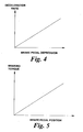
accelerator pedal 30 is equal to the speed that the vehicle will travel at on a smooth level road if the accelerator pedal in that position and thespeed control unit 22 operating in the normal mode. The target speed therefore increases steadily with depression of the accelerator pedal. Also, there is a separate target speed characteristic for each gear ratio of the transmission, as detected from the gearlever position sensor 29, since the road speed in normal mode is dependent on the gear ratio selected. - Referring to Figure 3, the target acceleration rate at (which is positive for acceleration and negative for deceleration) is set by the
speed control unit 22 and is controlled so as to vary in a predetermined manner with the difference between the target speed St and the measured road speed Sm. The characterised which determines the acceleration rate or deceleration rate is shown in Figure 3 and generally increases the target acceleration as the difference between the target speed St and the measured road speed Sm increases. The characteristic is shaped so as to correspond approximately to the behaviour of the vehicle in a smooth flat surface. The target acceleration rate is given by the formula: - As shown in Figure 2 there is for each gear a minimum target speed which is set at such a level that the engine will be running at idle speed, or slightly faster, when the vehicle is travelling at the minimum target speed. However this has the disadvantage that the speed control system cannot control the vehicle speed down to very low speeds or to a standstill. In order to overcome this problem, use can be made of known technology which provides automatic control of a vehicle clutch to provide controlled gear changes in a manual-type transmission. Basically this technology controls the engagement of the clutch automatically in response to movement of the manual gear select lever by the driver so as to provide a smooth gear change without the need for clutch control by the driver. The control system for this type of system could be modified so as to co-operate with the speed control system of the present invention by disengaging the clutch if the vehicle speed falls below that corresponding to engine idle speed. This would enable the vehicle speed to be controlled down to zero on a hill descent. For speed control on flat ground or on ascent of a hill, the system could also be modified so as to control the engagement of the clutch so as to maintain the target vehicle speed, whilst keeping the engine speed constant. This again would allow control for speeds down to zero.
- Referring to Figure 4 in the hill descent mode the
speed control unit 22 interprets the position of thebrake pedal 32 as a demand for deceleration. A target deceleration is defined for each position of the brake pedal, and the rate of deceleration increases with increasing depression of thebrake pedal 32. It then determines the best manner in which to provide the demanded level of deceleration. Generally engine braking will be used in preference to use of the disc brakes if it can produce the required level of braking. However the proportion of braking produced by the power train and the disc brakes may depend on the speed at which braking is required. In the event of a demand for sudden braking the disc brakes produce substantially all of the braking initially because they can respond much faster than the braking from the power train, but then as the engine braking available increases the braking torque from the disc brakes is reduced so as to keep the total deceleration at the required level. - Clearly if only one of the brake and accelerator pedals is depressed by the driver, the
speed control unit 22 can control the speed of the vehicle simply as described above. However, if both of the pedals are depressed thespeed control unit 22 needs to resolve the conflicting demands of the driver. This can be done in various ways. - The simplest is to use any demand for deceleration from the brake pedal to over-ride a demand for acceleration or speed from the accelerator pedal. Then if ever both pedals are depressed the signal from the accelerator pedal is ignored and the vehicle decelerated as requested by the position of the brake pedal.
- Another way of resolving the conflicting demands is to 'add together' the two demands to reach a net demand for acceleration or deceleration, and control the power train and brakes accordingly, as if the net demand were being given by the driver using only one of the pedals. This has the advantage that it is closer to what the driver would expect from a conventional vehicle but avoids the waste of energy caused when the brakes and power train are operated in conflict with each other.
- Referring to Figure 5 in a variant of the first embodiment, in the hill descent mode, the
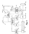
speed control unit 22 interprets the brake pedal position as a demand for a specific braking torque. Therefore for each position of the brake pedal a target braking torque is defined. The speed control unit then controls theengine 34 andbrakes 16 so as to produce the required braking torque. - Referring to Figure 6, in a second embodiment of the invention a vehicle includes an
engine 100 for producing drive which is input to a continuously variable transmission (CVT) 102 from which it is transmitted to thevehicle wheels 104, which havebrake discs 106 connected to them arranged to be acted on by hydraulically operatedbrake callipers 108. An electric motor /generator 109 which is operable as a starter motor for the engine, as a source of tractive drive torque, and as a generator to provide regenerative braking, is also included in the power train. The fuelling, air supply and spark timing of the engine are controlled by an engine management system (EMS) 110, the motor /generator 109 is controlled by amotor controller 111, and the ratio of the CVT is controlled by aCVT controller 112. TheEMS 110,motor controller 111, and theCVT controller 112 are all controlled by apower train controller 114. The brake fluid pressure to thecallipers 108 is controlled by a hydraulicbrake control unit 116 which comprises a valve block controlling the fluid pressure received from abrake master cylinder 118, operated by abrake pedal 120, and from apump 122. Thepower train controller 114 receives an input from anaccelerator pedal potentiometer 124. Aspeed controller 126 also receives inputs from theaccelerator pedal potentiometer 124, abrake pedal accelerometer 126 and a set ofwheel speed sensors 130 which enable it to determine the ground speed of the vehicle. - Under normal operation the accelerator pedal potentiometer signal is interpreted by the
power train controller 114 as a drive torque demand signal, and the power train controller provides an input to the EMS and to the CVT controller to request a suitable engine torque and transmission ratio to achieve the requested drive torque. The brakes are operated hydraulically at a braking pressure which is controlled directly by themaster cylinder 118, subject to an anti-lock function provided by the hydraulic brake control and a traction control function provided by thespeed control unit 126. - The
speed control unit 126 can, however be switched to a speed control mode in which the signal from theaccelerator pedal potentiometer 124 is interpreted as a speed demand signal and the signal from thebrake pedal potentiometer 128 is interpreted as a deceleration demand signal. In this case thespeed control unit 126 monitors the vehicle speed, compares it with a target speed and target acceleration or deceleration which are determined by the position of theaccelerator pedal 126 and thebrake pedal 126, determines the most appropriate source of the required drive or braking torque, and sends a torque demand signals to thepower train controller 114 or thebrake control unit 116 accordingly. - In many respects the control of this system is the same as that of the first embodiment. However with a larger number of sources of driving torque, which can be produced by the engine or the motor / generator and controlled using the transmission, and braking torque, which can be produced by the engine or the motor / generator or the brakes and also controlled using the transmission, the control parameters are clearly different. For example the level of charging of the battery associated with the motor / generator needs to be taken into consideration when determining levels of drive or braking torque the motor / generator can be asked to produce.
- In this embodiment the proportion of braking torque from the various sources can be varied with time as in the first embodiment so as to make use of their various characteristics. For example if the driver applied the
brake pedal 120 suddenly so as to demand a deceleration of 0.25g thebrakes motor 109. Then as the level of regenerative braking available from themotor 109 increases this is used increasingly instead of the brakes, whilst keeping the total level of braking constant as required by the driver. Finally the regenerative braking can provide the braking without any assistance from the brakes. - Whilst the embodiments described above both include hydraulic brake systems it will be apparent that electrically actuated brakes, as used in so called 'brake by wire' systems, could easily be controlled so as to form part of a similar system.
Claims (13)
- A vehicle speed control system comprising, driving means arranged to produce drive for the vehicle, braking means arranged to produce braking of the vehicle, vehicle speed measuring means for measuring the speed of the vehicle, a speed control unit, driver operated acceleration demand means and driver operated deceleration demand means, characterized in that the speed control unit is arranged to receive signals from the two demand means and to control the driving means and the braking means so as to produce the demanded level of acceleration or deceleration.
- A system according to claim 1 wherein the speed control means is arranged to define a target deceleration rate which is dependent on the position of the deceleration demand means and to control the driving means and the braking means so as to decelerate the vehicle at the demanded rate.
- A system according to claim 2 or claim 2 wherein, at least over a range of positions of the deceleration demand means, the speed control unit is arranged to define for each position of the deceleration demand means a target deceleration rate and control the driving means and the braking means so as to decelerate the vehicle at the demanded rate.
- A system according to any of claim 1 or claim 2 wherein the speed control means is arranged to define a target braking torque which is dependent on the position of the deceleration demand means and to control the driving means and the braking means so as to apply the demanded torque to the vehicle wheels.
- A system according to claim 4 wherein, at least over a range of positions of the deceleration demand means, the speed control unit is arranged to define for each position of the deceleration demand means a target braking torque and to control the driving means and the braking means so as to produce the demanded braking torque.
- A system according to any foregoing claim further comprising a drive control means arranged to control the drive means wherein the speed control unit is arranged to produce a torque demand signal indicative of the torque required from the drive means, and the drive control means is arranged to control the drive means so as to produce the required torque.
- A system according to any foregoing claim wherein the drive means is operable to produce a braking torque and the speed control means is arranged to co-ordinate operation of the drive means and the braking means to provide braking of the vehicle.
- A system according to claim 7 wherein the drive means includes an engine and the speed control means is arranged to control the engine so as to produce engine braking and driving torque as required.
- A system according to claim 7 or claim 8 wherein the drive means includes an electric motor and the speed control means is arranged to control the motor so as to produce regenerative braking and driving torque as required.
- A system according to any one of claims 7 to 9 wherein the drive means includes a transmission having a variable drive ratio and the speed control means is arranged to control the transmission so as to control braking torque and driving torque as required.
- A vehicle speed control system comprising an acceleration demand member movable through a range of positions, drive means, and a control unit arranged to control the drive means to control the speed of the vehicle in response to operation of the acceleration demand member, characterized in that the control means is operable in a first mode in which each of said positions has a target speed associated with it, such that when the acceleration demand means is in that position the control means is arranged to bring the vehicle speed towards the target speed, and a second mode in which each of said positions has a drive torque associated with it and the control means is arranged to control the drive means to produce the demanded torque substantially independently of the vehicle speed.
- A system according to claim 11 wherein the control means is arranged to control the drive means such that the rate at which the vehicle speed is brought towards the target speed is controlled so as to vary in a predefined manner with the difference between the measured speed of the vehicle and the target speed.
- A system according to claim 11 or claim 12 wherein the target speed associated with each of said range of positions of the speed control input member corresponds to the speed at which the vehicle would travel on a flat surface with the speed control input member in that position if the control means were in the second mode.
Applications Claiming Priority (2)
| Application Number | Priority Date | Filing Date | Title |
|---|---|---|---|
| GBGB9818960.8A GB9818960D0 (en) | 1998-09-02 | 1998-09-02 | A vehicle |
| GB9818960 | 1998-09-02 |
Publications (3)
| Publication Number | Publication Date |
|---|---|
| EP0983894A2 true EP0983894A2 (en) | 2000-03-08 |
| EP0983894A3 EP0983894A3 (en) | 2001-06-20 |
| EP0983894B1 EP0983894B1 (en) | 2007-07-11 |
Family
ID=10838109
Family Applications (1)
| Application Number | Title | Priority Date | Filing Date |
|---|---|---|---|
| EP99306948A Expired - Lifetime EP0983894B1 (en) | 1998-09-02 | 1999-09-01 | Vehicle speed control using engine and brake systems to achieve target acceleration |
Country Status (4)
| Country | Link |
|---|---|
| US (1) | US6283240B1 (en) |
| EP (1) | EP0983894B1 (en) |
| DE (1) | DE69936495T2 (en) |
| GB (2) | GB9818960D0 (en) |
Cited By (28)
| Publication number | Priority date | Publication date | Assignee | Title |
|---|---|---|---|---|
| EP0968893A3 (en) * | 1998-07-02 | 2001-02-28 | Rover Group Limited | Vehicle brake control |
| DE10036337A1 (en) * | 2000-07-26 | 2002-02-14 | Bayerische Motoren Werke Ag | Device and method for setting a target deceleration of a vehicle |
| NL1016457C2 (en) * | 2000-10-23 | 2002-04-24 | Skf Eng & Res Centre Bv | Spare braking system and method for electronically controlled (drive-by-wire) vehicle. |
| EP1297990A2 (en) * | 2001-09-26 | 2003-04-02 | Nissan Motor Company, Limited | Vehicle driving force control |
| EP1318285A1 (en) * | 2000-09-14 | 2003-06-11 | Toyota Jidosha Kabushiki Kaisha | Controller of variable cylinder engine and controller of vehicle |
| WO2003051663A1 (en) * | 2001-12-18 | 2003-06-26 | Robert Bosch Gmbh | Device and method for adjusting the speed of a vehicle |
| FR2843918A1 (en) * | 2002-08-27 | 2004-03-05 | Renault Sa | Method of controlling motor vehicle speed involves limiting speed if brake failure is detected, to allow limited driving for parking |
| EP1419924A1 (en) * | 2002-11-12 | 2004-05-19 | Hitachi Ltd. | Adaptive cruise control system |
| WO2004113112A1 (en) * | 2003-06-23 | 2004-12-29 | Toyota Jidosha Kabushiki Kaisha | Hybrid vehicle and method of controlling the same |
| FR2868362A1 (en) * | 2004-04-06 | 2005-10-07 | Peugeot Citroen Automobiles Sa | Motor vehicle speed regulating device, has regulating module to establish torque set point for output shaft of traction chain based on speed set point and measured speed, and control module to control chain with respect to torque set point |
| EP1683675A1 (en) | 2005-01-19 | 2006-07-26 | Magneti Marelli Powertrain S.p.A. | Cruise management method and device for a road vehicle |
| WO2007000266A1 (en) * | 2005-06-25 | 2007-01-04 | Bayerische Motoren Werke Aktiengesellschaft | Method for controlling a drive system and/or a wheel braking system |
| WO2007047849A2 (en) * | 2005-10-18 | 2007-04-26 | Daren Luedtke | Regenerative charging system using declelertion and/or wind |
| EP1928717A1 (en) * | 2005-09-08 | 2008-06-11 | Volvo Lastvagnar AB | Selective anti-lock braking system |
| FR2912978A1 (en) * | 2007-02-27 | 2008-08-29 | Peugeot Citroen Automobiles Sa | Speed control unit for motor vehicle engine, has braking system with control output controlling additional effect of braking when torque of engine brake delivered by engine is insufficient for restoring or maintaining speed below set speed |
| FR2929910A3 (en) * | 2008-04-11 | 2009-10-16 | Renault Sas | Hybrid drive train controlling method for motor vehicle, involves calculating torque set values from control data and rules by considering torque set values of chassis to determine torque set values transmitted to engine controllers |
| EP2006177A3 (en) * | 2007-05-22 | 2010-03-31 | Hitachi Ltd. | Vehicle speed control apparatus in accordance with curvature of vehicle trajectory |
| WO2010037494A1 (en) * | 2008-10-01 | 2010-04-08 | Robert Bosch Gmbh | System for controlling a regenerative drive and method for controlling a regenerative drive |
| GB2483720A (en) * | 2010-09-20 | 2012-03-21 | Land Rover Uk Ltd | Brake control that applies the brakes if determined acceleration exceeds an acceleration limit |
| EP2065271B1 (en) * | 2007-11-04 | 2013-04-03 | GM Global Technology Operations LLC | System architecture for a blended braking system in a hybrid powertrain system |
| FR3014060A1 (en) * | 2013-12-02 | 2015-06-05 | Peugeot Citroen Automobiles Sa | METHOD FOR CONTROLLING THE SPEED IN DOWNHILL OF A MOTOR VEHICLE, OPENING IN CERTAIN CONDITIONS THE TRACTION CHAIN |
| EP2789514A4 (en) * | 2011-12-09 | 2016-03-02 | Toyota Motor Co Ltd | Hybrid-vehicle control device |
| EP2789516A4 (en) * | 2011-12-09 | 2016-03-09 | Toyota Motor Co Ltd | Vehicle control device |
| CN105705389A (en) * | 2013-11-08 | 2016-06-22 | 标致·雪铁龙汽车公司 | Method for controlling the speed of a motor vehicle on a slope, which reduces the target speed according to the grip of the wheels |
| CN106218417A (en) * | 2016-08-18 | 2016-12-14 | 郑州宇通客车股份有限公司 | A kind of retarder brake control system and control method |
| GB2546767A (en) * | 2016-01-28 | 2017-08-02 | Jaguar Land Rover Ltd | Control system and method |
| EP2514953A4 (en) * | 2009-12-17 | 2018-06-27 | Toyota Jidosha Kabushiki Kaisha | Vehicle control device |
| USRE49258E1 (en) | 2002-04-18 | 2022-10-25 | Jaguar Land Rover Limited | Vehicle control |
Families Citing this family (41)
| Publication number | Priority date | Publication date | Assignee | Title |
|---|---|---|---|---|
| DE19925369B4 (en) * | 1999-06-02 | 2012-06-21 | Robert Bosch Gmbh | Method and device for controlling the speed of a vehicle |
| CA2385810A1 (en) * | 1999-10-29 | 2001-05-17 | Detroit Diesel Corporation | Vehicle passing speed timer |
| DE19960327A1 (en) * | 1999-12-15 | 2001-06-21 | Bosch Gmbh Robert | Electric drive for a vehicle |
| US6523630B2 (en) * | 2001-01-18 | 2003-02-25 | Delta Electronics, Inc. | Constant speed controlling device and method |
| JP2003291687A (en) * | 2002-04-04 | 2003-10-15 | Mitsubishi Fuso Truck & Bus Corp | Speed control device for vehicle |
| DE10246298B4 (en) * | 2002-10-02 | 2011-09-15 | Volkswagen Ag | Method for controlling a drive system and drive system |
| DE10303923A1 (en) * | 2003-01-31 | 2004-08-12 | Knorr-Bremse Systeme für Nutzfahrzeuge GmbH | Method for controlling a vehicle speed below a predetermined limit speed and device therefor |
| GB0310343D0 (en) * | 2003-05-06 | 2003-06-11 | Switched Reluctance Drives Ltd | A controller for a power train |
| US8145372B2 (en) * | 2004-02-11 | 2012-03-27 | Econtrols, Inc. | Watercraft speed control device |
| US7491104B2 (en) * | 2004-02-11 | 2009-02-17 | Econtrols, Inc. | Watercraft speed control device |
| US7877174B2 (en) * | 2005-02-11 | 2011-01-25 | Econtrols, Inc. | Watercraft speed control device |
| US7494394B2 (en) * | 2004-02-11 | 2009-02-24 | Econtrols, Inc. | Watercraft speed control device |
| US9052717B1 (en) | 2004-02-11 | 2015-06-09 | Enovation Controls, Llc | Watercraft speed control device |
| US7494393B2 (en) * | 2004-02-11 | 2009-02-24 | Econtrols, Inc. | Watercraft speed control device |
| US8475221B1 (en) | 2004-02-11 | 2013-07-02 | Econtrols, Inc. | Watercraft speed control device |
| US8521348B1 (en) | 2004-02-11 | 2013-08-27 | Econtrols, Inc. | Watercraft speed control device |
| US7485021B2 (en) * | 2004-02-11 | 2009-02-03 | Econtrols, Inc. | Watercraft speed control device |
| US20080243321A1 (en) * | 2005-02-11 | 2008-10-02 | Econtrols, Inc. | Event sensor |
| US7465203B2 (en) * | 2004-02-11 | 2008-12-16 | Econtrols, Inc. | Watercraft speed control device |
| US7580786B2 (en) * | 2004-02-26 | 2009-08-25 | Ford Global Technologies, Llc | Vehicle and nonlinear control method for vehicle |
| US9207675B1 (en) | 2005-02-11 | 2015-12-08 | Enovation Controls, Llc | Event sensor |
| US20080085642A1 (en) * | 2006-10-04 | 2008-04-10 | Econtrols, Inc. | Method for engaging a watercraft speed control system |
| US8112214B2 (en) * | 2007-03-16 | 2012-02-07 | GM Global Technology Oprations LLC | Model based vehicle overspeed algorithm |
| JP4938542B2 (en) * | 2007-04-27 | 2012-05-23 | トヨタ自動車株式会社 | Vehicle speed control device for vehicle |
| US7894967B2 (en) | 2007-05-30 | 2011-02-22 | Ford Global Technologies | Regenerative braking with hill descent control |
| US8082089B2 (en) * | 2008-07-23 | 2011-12-20 | GM Global Technology Operations LLC | Vehicle speed control in a cruise mode using vehicle brakes |
| JP5123864B2 (en) * | 2009-01-09 | 2013-01-23 | 本田技研工業株式会社 | Control device for belt type continuously variable transmission |
| US8308613B1 (en) * | 2009-07-23 | 2012-11-13 | Ryszard Nawrocki | Combination brake and accelerator pedal assembly |
| US8801575B1 (en) | 2009-07-23 | 2014-08-12 | Ryszard Nawrocki | Powered vehicle interlock system |
| JP5310948B2 (en) * | 2010-06-15 | 2013-10-09 | トヨタ自動車株式会社 | Driving support system |
| US8694217B2 (en) | 2010-10-05 | 2014-04-08 | Toyota Motor Engineering & Manufacturing North America, Inc. | Method and system for adjusting a gear map |
| US9156372B1 (en) | 2011-04-26 | 2015-10-13 | Enovation Controls, Llc | Multinodal ballast and trim control system and method |
| US20130197773A1 (en) * | 2012-01-31 | 2013-08-01 | Jeremy B. Shuler | Descent control of vehicle speed |
| JP5927717B2 (en) * | 2012-03-30 | 2016-06-01 | 本田技研工業株式会社 | Travel control device |
| US8845492B2 (en) | 2012-05-30 | 2014-09-30 | Cummins Inc. | Engine control override systems and methods |
| US8668625B1 (en) | 2012-10-04 | 2014-03-11 | Caterpillar Inc. | Cruise control using propulsion and retarding capabilities of machine |
| US9927776B2 (en) * | 2014-05-28 | 2018-03-27 | Ford Global Technologies, Llc | Intentionally increasing a non-torque output of an electric machine in an electric vehicle |
| US20160244039A1 (en) * | 2015-02-24 | 2016-08-25 | GM Global Technology Operations LLC | Vehicular crawl mode deceleration control |
| US9327732B1 (en) * | 2015-06-15 | 2016-05-03 | Ford Global Technologies, Llc | Method and assembly for changing thermal energy levels in a vehicle by adjusting engine braking |
| US20180111616A1 (en) * | 2016-10-25 | 2018-04-26 | NextEv USA, Inc. | Target speed control system which uses acceleration and brake pedals |
| CN112937314B (en) * | 2021-03-04 | 2023-03-21 | 广西玉柴机器股份有限公司 | Method and device for improving torque smoothness in regeneration mode |
Family Cites Families (24)
| Publication number | Priority date | Publication date | Assignee | Title |
|---|---|---|---|---|
| US4263997A (en) | 1975-10-17 | 1981-04-28 | Deere & Company | Vehicular single shaft gas turbine engine power system |
| DE2829894A1 (en) | 1978-07-07 | 1980-01-24 | Volkswagenwerk Ag | Speed control for IC engine vehicle - with correction signal for throttle setting derived from speed and rate of change of speed signals |
| DE3347070A1 (en) | 1983-12-24 | 1985-07-04 | Westfälische Metall Industrie KG Hueck & Co, 4780 Lippstadt | DEVICE FOR REGULATING THE SPEED OF A MOTOR VEHICLE |
| JPS60163731A (en) * | 1984-02-07 | 1985-08-26 | Nissan Motor Co Ltd | Car speed controlling device |
| DE3703645C2 (en) * | 1987-02-06 | 1998-08-06 | Bosch Gmbh Robert | Method for influencing the driving speed of a motor vehicle and device for carrying out the method |
| US5125485A (en) | 1988-10-07 | 1992-06-30 | Lang Ernest U | Motor vehicle movement control |
| US5646850A (en) | 1990-06-13 | 1997-07-08 | Matsushita Electric Industrial Co., Ltd. | Auto-drive control apparatus for use in vehicle apparatus |
| JPH06255389A (en) * | 1991-02-26 | 1994-09-13 | Mitsubishi Electric Corp | Traveling controller for vehicle |
| EP0570234B1 (en) | 1992-05-15 | 1999-11-24 | Mitsubishi Jidosha Kogyo Kabushiki Kaisha | Operating method for a hybrid car |
| SE9203163L (en) | 1992-10-26 | 1993-10-25 | Saab Scania Ab | Procedure and arrangement for constant cruising of motor vehicles |
| GB9303434D0 (en) | 1993-02-20 | 1993-04-07 | Lucas Ind Plc | Method of and apparatus for cruise control |
| GB2283338A (en) | 1993-10-26 | 1995-05-03 | Gen Motors Corp | Vehicle cruise control resume function |
| DE4338399B4 (en) * | 1993-11-10 | 2013-02-21 | Robert Bosch Gmbh | Method and device for controlling a vehicle |
| JPH0885362A (en) | 1994-09-20 | 1996-04-02 | Nissan Motor Co Ltd | Vehicle speed control device |
| GB9420561D0 (en) | 1994-10-12 | 1994-11-30 | Rover Group | A wheeled vehicle |
| GB2325716B (en) | 1994-10-12 | 1999-02-17 | Rover Group | A wheeled vehicle |
| SE504467C2 (en) | 1995-06-07 | 1997-02-17 | Volvo Ab | Cruise control device for motor vehicles |
| DE19530612C2 (en) | 1995-08-21 | 2002-06-27 | Daimler Chrysler Ag | Control of an automatic clutch |
| JP3624264B2 (en) * | 1995-09-28 | 2005-03-02 | アイシン精機株式会社 | Vehicle speed control device |
| DE19654769A1 (en) | 1996-12-30 | 1998-07-02 | Teves Gmbh Alfred | Method and device for vehicle control or regulation |
| SE9700456L (en) | 1997-02-11 | 1998-02-02 | Scania Cv Ab | Device for controlling the operation of a vehicle |
| EP0874149B1 (en) | 1997-04-25 | 2005-09-21 | Hitachi, Ltd. | Automotive control apparatus and method |
| GB9814258D0 (en) * | 1998-07-02 | 1998-09-02 | Rover Group | Vehicle brake control |
| GB9819519D0 (en) | 1998-09-09 | 1998-10-28 | Rover Group | Vehicle brake control |
-
1998
- 1998-09-02 GB GBGB9818960.8A patent/GB9818960D0/en not_active Ceased
-
1999
- 1999-08-31 US US09/387,152 patent/US6283240B1/en not_active Expired - Lifetime
- 1999-09-01 EP EP99306948A patent/EP0983894B1/en not_active Expired - Lifetime
- 1999-09-01 DE DE69936495T patent/DE69936495T2/en not_active Expired - Lifetime
- 1999-09-01 GB GB9920504A patent/GB2341245B/en not_active Expired - Lifetime
Non-Patent Citations (1)
| Title |
|---|
| None |
Cited By (56)
| Publication number | Priority date | Publication date | Assignee | Title |
|---|---|---|---|---|
| EP0968893A3 (en) * | 1998-07-02 | 2001-02-28 | Rover Group Limited | Vehicle brake control |
| DE10036337A1 (en) * | 2000-07-26 | 2002-02-14 | Bayerische Motoren Werke Ag | Device and method for setting a target deceleration of a vehicle |
| US7063394B2 (en) | 2000-07-26 | 2006-06-20 | Bayerische Motoren Werke Aktiengesellschaft | Method and apparatus for setting a desired deceleration of a vehicle |
| EP1318285A4 (en) * | 2000-09-14 | 2007-05-23 | Toyota Motor Co Ltd | Controller of variable cylinder engine and controller of vehicle |
| EP1318285A1 (en) * | 2000-09-14 | 2003-06-11 | Toyota Jidosha Kabushiki Kaisha | Controller of variable cylinder engine and controller of vehicle |
| EP1939433A3 (en) * | 2000-09-14 | 2009-04-22 | Toyota Jidosha Kabushiki Kaisha | Control apparatus for variable-cylinder engine, and control apparatus for vehicle |
| NL1016457C2 (en) * | 2000-10-23 | 2002-04-24 | Skf Eng & Res Centre Bv | Spare braking system and method for electronically controlled (drive-by-wire) vehicle. |
| WO2002034562A1 (en) * | 2000-10-23 | 2002-05-02 | Skf Engineering And Research Centre B.V. | Back-up braking system and method for drive-by-wire vehicle |
| EP1297990A2 (en) * | 2001-09-26 | 2003-04-02 | Nissan Motor Company, Limited | Vehicle driving force control |
| EP1297990A3 (en) * | 2001-09-26 | 2006-01-04 | Nissan Motor Company, Limited | Vehicle driving force control |
| WO2003051663A1 (en) * | 2001-12-18 | 2003-06-26 | Robert Bosch Gmbh | Device and method for adjusting the speed of a vehicle |
| US7416037B2 (en) | 2001-12-18 | 2008-08-26 | Robert Bosch Gmbh | Device and method for regulating the driving speed of a vehicle |
| USRE49258E1 (en) | 2002-04-18 | 2022-10-25 | Jaguar Land Rover Limited | Vehicle control |
| FR2843918A1 (en) * | 2002-08-27 | 2004-03-05 | Renault Sa | Method of controlling motor vehicle speed involves limiting speed if brake failure is detected, to allow limited driving for parking |
| EP1419924A1 (en) * | 2002-11-12 | 2004-05-19 | Hitachi Ltd. | Adaptive cruise control system |
| US7096109B2 (en) | 2002-11-12 | 2006-08-22 | Hitachi, Ltd. | Adaptive cruise control system |
| KR100710522B1 (en) * | 2003-06-23 | 2007-04-23 | 도요다 지도샤 가부시끼가이샤 | Hybrid vehicle and method of controlling the same |
| US7367414B2 (en) | 2003-06-23 | 2008-05-06 | Toyota Jidosha Kabushiki Kaisha | Hybrid vehicle and method of controlling the same |
| CN1809486B (en) * | 2003-06-23 | 2010-05-05 | 丰田自动车株式会社 | Hybrid vehicle and method of controlling the same |
| WO2004113112A1 (en) * | 2003-06-23 | 2004-12-29 | Toyota Jidosha Kabushiki Kaisha | Hybrid vehicle and method of controlling the same |
| FR2868362A1 (en) * | 2004-04-06 | 2005-10-07 | Peugeot Citroen Automobiles Sa | Motor vehicle speed regulating device, has regulating module to establish torque set point for output shaft of traction chain based on speed set point and measured speed, and control module to control chain with respect to torque set point |
| EP1683675A1 (en) | 2005-01-19 | 2006-07-26 | Magneti Marelli Powertrain S.p.A. | Cruise management method and device for a road vehicle |
| WO2007000266A1 (en) * | 2005-06-25 | 2007-01-04 | Bayerische Motoren Werke Aktiengesellschaft | Method for controlling a drive system and/or a wheel braking system |
| DE102005029528B4 (en) * | 2005-06-25 | 2018-01-04 | Bayerische Motoren Werke Aktiengesellschaft | Method for controlling a drive system and a wheel brake system |
| US8170763B2 (en) | 2005-06-25 | 2012-05-01 | Bayerische Motoren Werke Aktiengesellschaft | Method for controlling a drive system and/or wheel braking system |
| EP1928717A1 (en) * | 2005-09-08 | 2008-06-11 | Volvo Lastvagnar AB | Selective anti-lock braking system |
| US8126614B2 (en) | 2005-09-08 | 2012-02-28 | Volvo Lastvagnar Ab | Selective anti-lock braking system |
| EP1928717A4 (en) * | 2005-09-08 | 2010-09-22 | Volvo Lastvagnar Ab | Selective anti-lock braking system |
| WO2007047849A2 (en) * | 2005-10-18 | 2007-04-26 | Daren Luedtke | Regenerative charging system using declelertion and/or wind |
| WO2007047849A3 (en) * | 2005-10-18 | 2007-06-07 | Daren Luedtke | Regenerative charging system using declelertion and/or wind |
| FR2912978A1 (en) * | 2007-02-27 | 2008-08-29 | Peugeot Citroen Automobiles Sa | Speed control unit for motor vehicle engine, has braking system with control output controlling additional effect of braking when torque of engine brake delivered by engine is insufficient for restoring or maintaining speed below set speed |
| EP1964746A1 (en) * | 2007-02-27 | 2008-09-03 | Peugeot Citroën Automobiles S.A. | Control unit for a vehicle engine including a regulator and/or a speed limiter, and which can interact with an electronic braking system |
| EP2006177A3 (en) * | 2007-05-22 | 2010-03-31 | Hitachi Ltd. | Vehicle speed control apparatus in accordance with curvature of vehicle trajectory |
| CN101318509B (en) * | 2007-05-22 | 2011-05-04 | 株式会社日立制作所 | Vehicle speed control apparatus in accordance with curvature of vehicle trajectory |
| US8078381B2 (en) | 2007-05-22 | 2011-12-13 | Hitachi, Ltd. | Vehicle speed control apparatus in accordance with curvature of vehicle trajectory |
| EP2065271B1 (en) * | 2007-11-04 | 2013-04-03 | GM Global Technology Operations LLC | System architecture for a blended braking system in a hybrid powertrain system |
| US8594867B2 (en) | 2007-11-04 | 2013-11-26 | GM Global Technology Operations LLC | System architecture for a blended braking system in a hybrid powertrain system |
| FR2929910A3 (en) * | 2008-04-11 | 2009-10-16 | Renault Sas | Hybrid drive train controlling method for motor vehicle, involves calculating torque set values from control data and rules by considering torque set values of chassis to determine torque set values transmitted to engine controllers |
| WO2010037494A1 (en) * | 2008-10-01 | 2010-04-08 | Robert Bosch Gmbh | System for controlling a regenerative drive and method for controlling a regenerative drive |
| EP2514953A4 (en) * | 2009-12-17 | 2018-06-27 | Toyota Jidosha Kabushiki Kaisha | Vehicle control device |
| US9592804B2 (en) | 2010-09-20 | 2017-03-14 | Jaguar Land Rover Limited | Brake control |
| US10207688B2 (en) | 2010-09-20 | 2019-02-19 | Jaguar Land Rover Limited | Brake control |
| GB2483720B (en) * | 2010-09-20 | 2017-10-25 | Jaguar Land Rover Ltd | Improvements relating to brake control |
| GB2483720A (en) * | 2010-09-20 | 2012-03-21 | Land Rover Uk Ltd | Brake control that applies the brakes if determined acceleration exceeds an acceleration limit |
| EP2789516A4 (en) * | 2011-12-09 | 2016-03-09 | Toyota Motor Co Ltd | Vehicle control device |
| US9902390B2 (en) | 2011-12-09 | 2018-02-27 | Toyota Jidosha Kabushiki Kaisha | Vehicle control device |
| EP2789514A4 (en) * | 2011-12-09 | 2016-03-02 | Toyota Motor Co Ltd | Hybrid-vehicle control device |
| CN105705389A (en) * | 2013-11-08 | 2016-06-22 | 标致·雪铁龙汽车公司 | Method for controlling the speed of a motor vehicle on a slope, which reduces the target speed according to the grip of the wheels |
| CN105705389B (en) * | 2013-11-08 | 2019-05-28 | 标致·雪铁龙汽车公司 | Control the control method of the speed of motor vehicles on the slope |
| FR3014060A1 (en) * | 2013-12-02 | 2015-06-05 | Peugeot Citroen Automobiles Sa | METHOD FOR CONTROLLING THE SPEED IN DOWNHILL OF A MOTOR VEHICLE, OPENING IN CERTAIN CONDITIONS THE TRACTION CHAIN |
| CN105793132B (en) * | 2013-12-02 | 2018-07-27 | 标致·雪铁龙汽车公司 | The method for controlling motor vehicles descending speed by disconnecting power drive system in some cases |
| CN105793132A (en) * | 2013-12-02 | 2016-07-20 | 标致·雪铁龙汽车公司 | Method for controlling the downhill speed of a motor vehicle by switching on the power train in certain conditions |
| WO2015082785A1 (en) * | 2013-12-02 | 2015-06-11 | Peugeot Citroen Automobiles Sa | Method for controlling the downhill speed of a motor vehicle by switching on the power train in certain conditions |
| GB2546767A (en) * | 2016-01-28 | 2017-08-02 | Jaguar Land Rover Ltd | Control system and method |
| GB2546767B (en) * | 2016-01-28 | 2018-11-07 | Jaguar Land Rover Ltd | Vehicle speed control system and method |
| CN106218417A (en) * | 2016-08-18 | 2016-12-14 | 郑州宇通客车股份有限公司 | A kind of retarder brake control system and control method |
Also Published As
| Publication number | Publication date |
|---|---|
| GB2341245B (en) | 2003-04-09 |
| GB2341245A (en) | 2000-03-08 |
| EP0983894B1 (en) | 2007-07-11 |
| US6283240B1 (en) | 2001-09-04 |
| EP0983894A3 (en) | 2001-06-20 |
| DE69936495D1 (en) | 2007-08-23 |
| GB9920504D0 (en) | 1999-11-03 |
| GB9818960D0 (en) | 1998-10-21 |
| DE69936495T2 (en) | 2008-03-13 |
Similar Documents
| Publication | Publication Date | Title |
|---|---|---|
| EP0983894B1 (en) | Vehicle speed control using engine and brake systems to achieve target acceleration | |
| US5915801A (en) | Regenerative brake controller for controlling value of regenerative braking torque simulating engine braking torque | |
| CN107298101B (en) | Cruise control system and power transmission system for vehicle and control method thereof | |
| US5615933A (en) | Electric vehicle with regenerative and anti-lock braking | |
| JP3915391B2 (en) | Braking force control device for vehicle | |
| EP2557302B1 (en) | Vehicle control device | |
| US8392087B2 (en) | Vehicle control system | |
| US7739021B2 (en) | Adaptive retarder control method and apparatus | |
| US5964680A (en) | Power train for a motor vehicle | |
| JP6726272B2 (en) | Vehicle speed control method and vehicle speed control system | |
| US10821948B2 (en) | Electric parking brake with regenerative braking control system and method | |
| JP3358509B2 (en) | Travel control device for vehicles | |
| JP6596151B2 (en) | Vehicle speed control method and vehicle speed control system | |
| US6896340B2 (en) | System and method for maintaining a vehicle at zero speed on a graded surface | |
| KR20040108712A (en) | Method, device and use thereof for operating a motor vehicle | |
| EP0968893B1 (en) | Vehicle brake control | |
| US6283239B1 (en) | Auxiliary brake apparatus of hybrid automobile | |
| EP1283341B1 (en) | A vehicle speed control system | |
| JP2000511850A (en) | Brake signal forming device for vehicles | |
| EP0839684B1 (en) | A system for controlling parking and hill-starting of a motor-vehicle | |
| JP2004504224A (en) | Apparatus and method for setting a target deceleration of a vehicle | |
| JP2505260B2 (en) | Vehicle traction control device | |
| JP2534732B2 (en) | Drive force distribution controller for four-wheel drive vehicle | |
| WO2021229370A1 (en) | Apparatus for the braking process of a vehicle with a trailer | |
| JPH08108836A (en) | Braking force control device |
Legal Events
| Date | Code | Title | Description |
|---|---|---|---|
| PUAI | Public reference made under article 153(3) epc to a published international application that has entered the european phase |
Free format text: ORIGINAL CODE: 0009012 |
|
| AK | Designated contracting states |
Kind code of ref document: A2 Designated state(s): DE ES FR IT SE |
|
| AX | Request for extension of the european patent |
Free format text: AL;LT;LV;MK;RO;SI |
|
| RIC1 | Information provided on ipc code assigned before grant |
Free format text: 7B 60K 41/20 A, 7B 60K 31/04 B, 7B 60K 31/10 B, 7B 60T 7/12 B, 7B 60T 13/58 B |
|
| PUAL | Search report despatched |
Free format text: ORIGINAL CODE: 0009013 |
|
| RAP1 | Party data changed (applicant data changed or rights of an application transferred) |
Owner name: LAND ROVER GROUP LIMITED |
|
| AK | Designated contracting states |
Kind code of ref document: A3 Designated state(s): AT BE CH CY DE DK ES FI FR GB GR IE IT LI LU MC NL PT SE |
|
| AX | Request for extension of the european patent |
Free format text: AL;LT;LV;MK;RO;SI |
|
| 17P | Request for examination filed |
Effective date: 20011112 |
|
| AKX | Designation fees paid |
Free format text: DE ES FR IT SE |
|
| RAP1 | Party data changed (applicant data changed or rights of an application transferred) |
Owner name: LAND ROVER |
|
| GRAC | Information related to communication of intention to grant a patent modified |
Free format text: ORIGINAL CODE: EPIDOSCIGR1 |
|
| GRAP | Despatch of communication of intention to grant a patent |
Free format text: ORIGINAL CODE: EPIDOSNIGR1 |
|
| RIC1 | Information provided on ipc code assigned before grant |
Ipc: B60W 10/18 20060101ALI20061220BHEP Ipc: B60W 10/04 20060101ALI20061220BHEP Ipc: B60W 30/18 20060101AFI20061220BHEP |
|
| GRAS | Grant fee paid |
Free format text: ORIGINAL CODE: EPIDOSNIGR3 |
|
| GRAA | (expected) grant |
Free format text: ORIGINAL CODE: 0009210 |
|
| RBV | Designated contracting states (corrected) |
Designated state(s): DE FR |
|
| AK | Designated contracting states |
Kind code of ref document: B1 Designated state(s): DE FR |
|
| REF | Corresponds to: |
Ref document number: 69936495 Country of ref document: DE Date of ref document: 20070823 Kind code of ref document: P |
|
| ET | Fr: translation filed | ||
| PLBE | No opposition filed within time limit |
Free format text: ORIGINAL CODE: 0009261 |
|
| STAA | Information on the status of an ep patent application or granted ep patent |
Free format text: STATUS: NO OPPOSITION FILED WITHIN TIME LIMIT |
|
| 26N | No opposition filed |
Effective date: 20080414 |
|
| REG | Reference to a national code |
Ref country code: DE Ref legal event code: R082 Ref document number: 69936495 Country of ref document: DE Representative=s name: ANDRAE WESTENDORP PATENTANWAELTE PARTNERSCHAFT, DE |
|
| REG | Reference to a national code |
Ref country code: FR Ref legal event code: PLFP Year of fee payment: 18 |
|
| REG | Reference to a national code |
Ref country code: FR Ref legal event code: PLFP Year of fee payment: 19 |
|
| REG | Reference to a national code |
Ref country code: FR Ref legal event code: PLFP Year of fee payment: 20 |
|
| PGFP | Annual fee paid to national office [announced via postgrant information from national office to epo] |
Ref country code: FR Payment date: 20180822 Year of fee payment: 20 Ref country code: DE Payment date: 20180821 Year of fee payment: 20 |
|
| REG | Reference to a national code |
Ref country code: DE Ref legal event code: R082 Ref document number: 69936495 Country of ref document: DE |
|
| REG | Reference to a national code |
Ref country code: DE Ref legal event code: R071 Ref document number: 69936495 Country of ref document: DE |