EP0982960A1 - Radiocommunication network test procedure and corresponding device and base station - Google Patents
Radiocommunication network test procedure and corresponding device and base station Download PDFInfo
- Publication number
- EP0982960A1 EP0982960A1 EP99460053A EP99460053A EP0982960A1 EP 0982960 A1 EP0982960 A1 EP 0982960A1 EP 99460053 A EP99460053 A EP 99460053A EP 99460053 A EP99460053 A EP 99460053A EP 0982960 A1 EP0982960 A1 EP 0982960A1
- Authority
- EP
- European Patent Office
- Prior art keywords
- signals
- reception
- base station
- jammer
- interference
- Prior art date
- Legal status (The legal status is an assumption and is not a legal conclusion. Google has not performed a legal analysis and makes no representation as to the accuracy of the status listed.)
- Granted
Links
Images


Classifications
-
- H—ELECTRICITY
- H04—ELECTRIC COMMUNICATION TECHNIQUE
- H04W—WIRELESS COMMUNICATION NETWORKS
- H04W16/00—Network planning, e.g. coverage or traffic planning tools; Network deployment, e.g. resource partitioning or cells structures
- H04W16/24—Cell structures
- H04W16/28—Cell structures using beam steering
-
- H—ELECTRICITY
- H01—ELECTRIC ELEMENTS
- H01Q—ANTENNAS, i.e. RADIO AERIALS
- H01Q1/00—Details of, or arrangements associated with, antennas
- H01Q1/12—Supports; Mounting means
- H01Q1/22—Supports; Mounting means by structural association with other equipment or articles
- H01Q1/24—Supports; Mounting means by structural association with other equipment or articles with receiving set
- H01Q1/241—Supports; Mounting means by structural association with other equipment or articles with receiving set used in mobile communications, e.g. GSM
- H01Q1/246—Supports; Mounting means by structural association with other equipment or articles with receiving set used in mobile communications, e.g. GSM specially adapted for base stations
Definitions
- the field of the invention is that of radiocommunication systems with mobile.
- the invention applies in particular, but not exclusively, in systems UMTS type radio communication (for "Universal Mobile Telecommunication System - 2 GHz "in English) or GSM 900 (for" Global System for Mobile- 900 MHz “ in English or "Public Mobile Radio Systems Special Group operating in the 900 MHz band "), DCS 1800 (for” Digital Cellular System - 1800 MHz “in English) or PCS 1900 (for” Personal Communication System - 1900 MHz "in English).
- the present invention relates to a method for testing a network. of radio communication consisting in detecting and elucidating interference between at least two transmitters, namely on the one hand a mobile station, transmitting useful signals in direction of a base station, and on the other hand at least one jammer, transmitting interference signals also in the direction of the base station.
- a radiocommunication system includes a plurality of base stations, each providing radio coverage for a separate geographic unit.
- jammer means any type of device transmitting towards a base station with which the given mobile station communicates, signals having at least certain characteristics identical or similar to those of the signals from the given mobile station.
- the mobile station is sometimes called the terminal radiocommunication, mobile radiotelephone, mobile phone or terminal mobile radio.
- a mobile station is physical equipment used by a user of a radiocommunication system network to access, via a basic, telecommunications services offered.
- a base station covers a geographical area data (or cell) in which a plurality of mobile stations can move with which the base station can exchange signals.
- a base station comprises at least one antenna intended to receive and / or transmit signals from and / or to a plurality of mobile stations.
- Signals exchanged between a mobile station and the base station may be subject to interference that can generate a partial or even total loss of information vehicles. It is recalled that the interference phenomena are caused in particular when signals of identical or similar characteristics are involved in a same propagation medium.
- identical or similar characteristics is meant by example the same frequency, the same code or the same time interval, depending on whether the system implements respectively frequency multiplexing (or FDMA, for "Frequency Division Multiple Access” in English or “Multiple Access by Distribution in Fréquence "in French), by code (or CDMA, for" Coded Division Multiple Access "in English or “Multiple Access by Distribution in Code” in French) or temporal (or TDMA, for "Time Division Multiple Access” in English or “Multiple Access by Distribution in Temps "in French).
- the interference is due to the presence of minus a jammer transmitting signals (called “interference") which disturb the signals (called “useful”) transmitted by a mobile station. It will therefore be understood that such disturbances can cause crucial problems with reception quality and of signals transmitted by a mobile station and intended for a base station.
- the object of the present invention is in particular to overcome this drawback of the state of the art.
- one of the objectives of the present invention is to provide a method of testing a radio network for detecting the presence at least one jammer.
- An additional objective of the invention is to provide such a method allowing to determine the possible nature of the jammer (s).
- Another object of the invention is to provide such a method which can be implemented works without any modification of the signals exchanged between a mobile station and a base station.
- Another object of the invention is to provide such a method which can be implemented work, without any material modification of the existing mobile stations, nor, possibly base stations.
- Another object of the invention is to provide a device allowing the implementation implementation of such a test method for a radiocommunication network.
- Another object of the invention is to provide a base station enabling the implementation of such a test method for a radiocommunication network.
- the general principle of the invention therefore rests on the simultaneous focusing of several radio receiving beams (one per antenna) respectively on different signal sources (i.e. a useful signal source and one or more possible source (s) of interference signals). So at least one reception chain is assigned to the processing of possible interference signals.
- first antenna is used and “second” antenna (called “intelligent” antenna). to simplify the understanding of the invention. It is clear however that it is not compulsory that there are as many antennas that there are reception chains. The same antenna can supply several (or even all) reception chains. In other words, the first and second antennas can form a single antenna.
- an antenna associated with a reception chain forms a beam radio receiving radiator, which can be oriented in elevation (i.e. the angle formed by the line connecting the mobile station to the antenna with the horizontal plane containing the antenna support) and / or azimuth (i.e. the angle formed between a reference line in the horizontal plane containing the antenna support and the projection, direction perpendicular to this horizontal plane, of the line connecting the antenna to the mobile station).
- the nature of the jammer (s) may be arbitrary, and may in particular correspond to that of an emitter (s) foreign to any network of radiocommunication.
- the method of the invention constitutes a technique for detecting imperfections in the radio network concerned.
- this reflects poor management of the distribution of resources such as a double assignment of the same resource. This is for example the case of two base stations neighbors (or relatively close) who both use at least the same communication parameter, such as a frequency, a code, a time interval, ..., to each communicate with a separate mobile station.
- the first and second antennas constitute only one and same antenna.
- the invention also relates to a base station for detecting and elucidating interference between at least two transmitters, namely on the one hand a mobile station transmitting useful signals towards said base station, and on the other hand at least a jammer transmitting interference signals also towards said station based.
- said base station comprises the device for testing a network radio communication described above.
- certain elements are elements already included in the base station to allow the latter to communicate with the mobile stations. In this case, it there is a strong synergy and the cost of the test device is therefore reduced to only the elements not already included in the base station.
- the invention therefore relates to a method and a device for testing a network of radio communication consisting in detecting and elucidating interference between at least two transmitters, namely a mobile station transmitting useful signals towards a base station and at least one jammer transmitting interference signals also in base station management.
- a single jammer B transmits interference signals which interfere with wanted signals from a MS mobile station being communication with a BTS base station. It is clear, however, that the process of the invention can simultaneously allow the detection of a plurality of jammers, in for example using a plurality of reception chains (each allowing to detect a jammer). These different signals (useful and interference) are received via separate radio receiving beams.
- a single antenna can be connected to the two signal reception channels (useful and scrambling).
- the single antenna constitutes the material part and the two reception chains are managed by means software.
- the radiocommunication system cellular to which the base station and the mobile station belong is of the UMTS type and using FDD-WCDMA multiplexing at the frequency of 2 GHz.
- W-CDMA mode for "Wide band Code Division Multiple Access” in English
- ETSI decision of January 1998 concerning UMTS (“Universal Mobile Telecommunication System "), this decision being inserted here by reference. effect that the UMTS radio interface was broadly stopped in January 1998.
- W-CDMA mode uses CDMA access on a 5 MHz channel.
- the base station and the mobile station can also be understood in systems for example of the GSM 900 or DCS 1800 type or even of the type PCS 1900 ...
- the method further comprises a step (17) display of the identifier or the absence of an identifier for the jammer and / or the direction of arrival of the interference signals.
- a step (17) display of the identifier or the absence of an identifier for the jammer and / or the direction of arrival of the interference signals An operator who uses the the invention thus visualizes the nature of the jammer and / or the precise origin of the interference.
- Such a method allows, for a given communication, not only to detect the presence of a jammer in the cell associated with the base station concerned (or in an environment close to this cell), but also to provide information the operator in the area where the jammer is located.
- This area includes in particular the area covered by the associated receiving radioelectric beam to the corresponding reception chain (i.e. either the first or the second chain reception).
- the reception quality by the base station of the useful signals transmitted by the mobile station can then be improved.
- a base station 21 is located at a site 20 defining the center of a cell data assigned to it, in which it can receive and transmit signals.
- a device 22 for testing a radiocommunication network is placed on the same site 20 than that of the base station 21, for example at the origin O of the three-dimensional coordinate system (Ox, Oy, Oz).
- Such a device 22 is intended to implement the method described previously, in order to detect and elucidate interference between two transmitters, knowing on the one hand a mobile station (MS) 24 transmitting useful signals towards the base station 21 and on the other hand a jammer (B) 23 transmitting interference signals also towards base station 21.
- MS mobile station
- B jammer
- the device 22 includes two intelligent directional antennas 310a, 310b as explained in detail below (see Figure 3).
- a directive smart antenna or smart antenna with beam adaptation (“Adaptive Smart Antennas”), includes a network of elements radiant distributed matrically on a support (or panel).
- the network of elements radiant is composed of a plurality of columns of radiating elements, controlled generally each independently of the others, so as to form a bundle according to a given azimuth.
- the device 22 for testing a radiocommunication network controls the antennas 310a, 310b, so that these generate two radiating beams 25, 26 radio directional, and oriented in azimuth, towards mobile station 24 and the possible jammer 23.
- a first radiation pattern 26 of the antenna 310b is pointed (or even focused) on the mobile station 24 in communication and a second radiation diagram 25 of the antenna 310a is pointed to the possible jammer 23.
- the radio reception beams 25, 26 can therefore be oriented in azimuth and in elevation, according to two pairs of angles ( ⁇ 1 ; ⁇ 1 ) and ( ⁇ 1 ; ⁇ 2 ) respectively, with ⁇ 1 and ⁇ 2 the angles d 'azimuth, and ⁇ 1 and ⁇ 2 the elevation angles.
- the pairs of angles ( ⁇ 1 ; ⁇ 1 ) and ( ⁇ 2 ; ⁇ 2 ) represent two distinct directions of arrival of the wanted signals and the interference signals.
- the jammer 23 can be an element belonging to the radiocommunication which includes mobile station 24 and base station 21. It can therefore be a neighboring mobile station or base station. Jammer 23 can also be a foreign element in the radiocommunication network.
- the device 22 further comprises means 34 for displaying the identifier or the absence of the jammer 23 identifier and / or the direction of arrival of the interference.
- An operator 35 can consult the results of the search for jammer (s) for a given communication between the mobile station 24 and the base station 21 which uses the device 21 described above.
- the operator 35 can, as soon as he is informed (for example by display), modify the or the corresponding communication parameter (s) to eliminate interference. he may in particular be an intervention at a neighboring base station presenting an anomaly or a defective mobile station, some of which characteristics (and in particular those influencing the signals exchanged) are to be modified.
- the information available on the jammer i.e. its angular position by report to the base station
- the competent authorities responsible for mittees allocation of resources, police, etc.
- the device 22 for testing a network of radio communication described above is included in the base station 21 of the radiocommunication, and reuse part of the means constituting the latter.
- the base station is of the type implementing a spatial multiplexing (or "SDMA” for "Spatial Division Multiple Access” in English or “Multiple Access to Distribution in Space” in French), so it uses in particular a radioelectric receiving beam directional and orientable using means electronic, so as to "follow" the mobile station during its movement within the cell, to communicate with her.
- the base station therefore comprises at least one first intelligent directive antenna 310a and a reception chain 3 la as described previously, to communicate with the mobile station during communication. So, just add a second smart directive antenna and a second chain reception at the base station, unless certain means (in particular decoding and / or reading) of this second chain can be shared with the test device of a radiocommunication network.
- the base station is not of the type setting up performs spatial multiplexing, and implements for example frequency multiplexing (or FDMA) or a time division multiplexing (or TDMA) or even by code (or CDMA), then it is necessary to build the test device according to the invention to provide at at least two additional smart antennas and at least some of the different reception chains (in particular means of allocation of the different reception channels, decoding means and decision-making means).
- FDMA frequency multiplexing
- TDMA time division multiplexing
- CDMA code
Abstract
Description
Le domaine de l'invention est celui des systèmes de radiocommunication avec des mobiles.The field of the invention is that of radiocommunication systems with mobile.
L'invention s'applique notamment, mais non exclusivement, dans des systèmes de radiocommunication de type UMTS (pour "Universal Mobile Telecommunication System - 2 GHz" en anglais) ou GSM 900 (pour "Global System for Mobile- 900 MHz" en anglais ou "Groupe spécial Systèmes Mobiles publics de radiocommunication fonctionnant dans la bande des 900 MHz"), DCS 1800 (pour "Digital Cellular System - 1800 MHz" en anglais) ou PCS 1900 (pour "Personal Communication System - 1900 MHz" en anglais).The invention applies in particular, but not exclusively, in systems UMTS type radio communication (for "Universal Mobile Telecommunication System - 2 GHz "in English) or GSM 900 (for" Global System for Mobile- 900 MHz " in English or "Public Mobile Radio Systems Special Group operating in the 900 MHz band "), DCS 1800 (for" Digital Cellular System - 1800 MHz "in English) or PCS 1900 (for" Personal Communication System - 1900 MHz "in English).
Plus précisément, la présente invention concerne un procédé de test d'un réseau de radiocommunication consistant à détecter et élucider les interférences entre au moins deux émetteurs, à savoir d'une part une station mobile, émettant des signaux utiles en direction d'une station de base, et d'autre part au moins un brouilleur, émettant des signaux de brouillage également dans la direction de la station de base.More specifically, the present invention relates to a method for testing a network. of radio communication consisting in detecting and elucidating interference between at least two transmitters, namely on the one hand a mobile station, transmitting useful signals in direction of a base station, and on the other hand at least one jammer, transmitting interference signals also in the direction of the base station.
On rappelle que, d'une façon générale, un système de radiocommunication comprend une pluralité de stations de base, chacune assurant la couverture radio d'une cellule géographique distincte.It is recalled that, in general, a radiocommunication system includes a plurality of base stations, each providing radio coverage for a separate geographic unit.
Dans la suite de la présente description, par le terme "brouilleur" (vis-à-vis d'une station mobile donnée), on entend tout type de dispositif émettant, en direction d'une station de base avec laquelle communique la station mobile donnée, des signaux présentant au moins certaines caractéristiques identiques ou similaires à celles des signaux issus de la station mobile donnée.In the remainder of this description, by the term "jammer" (with respect to a given mobile station) means any type of device transmitting towards a base station with which the given mobile station communicates, signals having at least certain characteristics identical or similar to those of the signals from the given mobile station.
Selon les systèmes, la station mobile est parfois appelée terminal de radiocommunication, radiotéléphone mobile, téléphone portable ou encore terminal mobile de radiocommunication. Par souci de simplification, on emploie uniquement, dans la suite de ce document de brevet, l'expression "station mobile".Depending on the system, the mobile station is sometimes called the terminal radiocommunication, mobile radiotelephone, mobile phone or terminal mobile radio. For the sake of simplification, only in following this patent document, the expression "mobile station".
On rappelle qu'une station mobile est un équipement physique utilisé par un usager d'un réseau du système de radiocommunication pour accéder, via une station de base, aux services de télécommunication offerts.It is recalled that a mobile station is physical equipment used by a user of a radiocommunication system network to access, via a basic, telecommunications services offered.
On rappelle également qu'une station de base couvre une zone géographique donnée (ou cellule) dans laquelle peuvent se déplacer une pluralité de stations mobiles avec lesquels la station de base peut échanger des signaux. De façon classique, une station de base comprend au moins une antenne destinée à recevoir et/ou émettre des signaux depuis et/ou vers une pluralité de stations mobiles.It is also recalled that a base station covers a geographical area data (or cell) in which a plurality of mobile stations can move with which the base station can exchange signals. Typically, a base station comprises at least one antenna intended to receive and / or transmit signals from and / or to a plurality of mobile stations.
Les signaux échangés entre une station mobile et la station de base peuvent subir des interférences pouvant générer une perte partielle, voire totale, des informations véhiculées. On rappelle que les phénomènes d'interférences sont provoqués notamment lorsque des signaux de caractéristiques identiques ou similaires sont mis en jeu dans un même milieu de propagation. Par caractéristiques identiques ou similaires, on entend par exemple une même fréquence, un même code ou un même intervalle de temps, selon que le système met en oeuvre respectivement un multiplexage fréquentiel (ou FDMA, pour "Frequency Division Multiple Access" en anglais ou "Accès Multiple par Répartition en Fréquence" en français), par code (ou CDMA, pour "Coded Division Multiple Access" en anglais ou "Accès Multiple par Répartition en Code" en français) ou temporel (ou TDMA, pour "Time Division Multiple Access" en anglais ou "Accès Multiple par Répartition en Temps" en français). En d'autres termes, les interférences sont dues à la présence d'au moins un brouilleur émettant des signaux (dits "de brouillage") qui perturbent les signaux (dits "utiles") émis par une station mobile. On comprendra donc que de telles perturbations peuvent engendrer des problèmes cruciaux quant à la qualité de réception et d'exploitation des signaux émis par une station mobile et destinés à une station de base.Signals exchanged between a mobile station and the base station may be subject to interference that can generate a partial or even total loss of information vehicles. It is recalled that the interference phenomena are caused in particular when signals of identical or similar characteristics are involved in a same propagation medium. By identical or similar characteristics, is meant by example the same frequency, the same code or the same time interval, depending on whether the system implements respectively frequency multiplexing (or FDMA, for "Frequency Division Multiple Access" in English or "Multiple Access by Distribution in Fréquence "in French), by code (or CDMA, for" Coded Division Multiple Access "in English or "Multiple Access by Distribution in Code" in French) or temporal (or TDMA, for "Time Division Multiple Access" in English or "Multiple Access by Distribution in Temps "in French). In other words, the interference is due to the presence of minus a jammer transmitting signals (called "interference") which disturb the signals (called "useful") transmitted by a mobile station. It will therefore be understood that such disturbances can cause crucial problems with reception quality and of signals transmitted by a mobile station and intended for a base station.
Or, l'état actuel de la technique ne permet pas de déceler la présence de brouilleur(s). On comprendra cependant qu'il est nécessaire, pour diminuer voire supprimer les interférences dues à un ou plusieurs brouilleur(s), de connaítre leur existence et éventuellement leur nature, afin de prendre des mesures appropriées pour tenter de les supprimer.However, the current state of the art does not make it possible to detect the presence of jammer (s). It will however be understood that it is necessary, in order to decrease or even remove the interference due to one or more jammer (s), to know their existence and possibly their nature, in order to take appropriate measures to try to delete them.
La présente invention a notamment pour objectif de pallier cet inconvénient de l'état de la technique.The object of the present invention is in particular to overcome this drawback of the state of the art.
Plus précisément, l'un des objectifs de la présente invention est de fournir un procédé de test d'un réseau de radiocommunication permettant de détecter la présence d'au moins un brouilleur.More specifically, one of the objectives of the present invention is to provide a method of testing a radio network for detecting the presence at least one jammer.
Un objectif supplémentaire de l'invention est de fournir un tel procédé permettant de déterminer la nature éventuelle du ou des brouilleur(s).An additional objective of the invention is to provide such a method allowing to determine the possible nature of the jammer (s).
Un autre objectif de l'invention est de fournir un tel procédé pouvant être mis en oeuvre sans aucune modification des signaux échangés entre une station mobile et une station de base.Another object of the invention is to provide such a method which can be implemented works without any modification of the signals exchanged between a mobile station and a base station.
Un autre objectif de l'invention est de fournir un tel procédé pouvant être mis en oeuvre, sans aucune modification matérielle des stations mobiles existantes, ni, éventuellement, des stations de base.Another object of the invention is to provide such a method which can be implemented work, without any material modification of the existing mobile stations, nor, possibly base stations.
Un autre objectif de l'invention est de fournir un dispositif permettant la mise en oeuvre d'un tel procédé de test d'un réseau de radiocommunication.Another object of the invention is to provide a device allowing the implementation implementation of such a test method for a radiocommunication network.
Un autre objectif de l'invention est de fournir une station de base permettant la mise en oeuvre d'un tel procédé de test d'un réseau de radiocommunication.Another object of the invention is to provide a base station enabling the implementation of such a test method for a radiocommunication network.
Ces différents objectifs, ainsi que d'autres qui apparaítront par la suite, sont atteints selon l'invention à l'aide d'un procédé de test d'un réseau de radiocommunication consistant à détecter et élucider les interférences entre au moins deux émetteurs, à savoir d'une part une station mobile émettant des signaux utiles en direction d'une station de base, et d'autre part au moins un brouilleur émettant des signaux de brouillage également en direction de ladite station de base comprenant les étapes suivantes :
- on met en oeuvre, en aval d'une première antenne, une première chaíne de réception, et en aval d'au moins une seconde antenne, au moins une seconde chaíne de réception distincte de ladite première chaíne de réception, chaque antenne comprenant un réseau d'éléments rayonnants répartis matriciellement sur un support;
- on affecte ladite première chaíne de réception à la réception de premiers signaux, selon une première direction d'arrivée ;
- on affecte ladite au moins une seconde chaíne de réception à la réception de seconds signaux, selon au moins une seconde direction d'arrivée ;
- chaque chaíne de réception tente de décoder les signaux qu'elle reçoit, et si le
décodage peut être effectué, lit un identifiant véhiculé par les signaux et propre à
l'émetteur qui les a émis, de façon à déterminer d'une part lesquels desdits
premiers et seconds signaux sont lesdits signaux de brouillage, et d'autre part au
moins une des informations appartenant au groupe comprenant :
- la direction d'arrivée desdits signaux de brouillage ;
- l'identifiant éventuel dudit au moins un brouilleur émettant lesdits signaux de brouillage.
- we implement, downstream of a first antenna, a first reception chain, and downstream of at least a second antenna, at least a second reception chain distinct from said first reception chain, each antenna comprising a network radiating elements distributed matrically on a support;
- assigning said first reception chain to the reception of first signals, in a first direction of arrival;
- said at least one second reception chain is assigned to the reception of second signals, according to at least a second direction of arrival;
- each reception chain tries to decode the signals it receives, and if the decoding can be carried out, reads an identifier conveyed by the signals and specific to the transmitter which transmitted them, so as to determine on the one hand which of the said first and second signals are said interference signals, and on the other hand at least one of the pieces of information belonging to the group comprising:
- the direction of arrival of said interference signals;
- the possible identifier of said at least one jammer transmitting said jamming signals.
Le principe général de l'invention repose donc sur la focalisation simultanée de plusieurs faisceaux rayonnants radioélectriques de réception (un par antenne) respectivement sur différentes sources de signaux (à savoir une source de signaux utiles et une ou plusieurs éventuelle(s) source(s) de signaux de brouillage). Ainsi, au moins une chaíne de réception se trouve affectée au traitement des éventuels signaux de brouillage.The general principle of the invention therefore rests on the simultaneous focusing of several radio receiving beams (one per antenna) respectively on different signal sources (i.e. a useful signal source and one or more possible source (s) of interference signals). So at least one reception chain is assigned to the processing of possible interference signals.
De cette manière, il est possible non seulement de savoir si un ou des brouilleur(s) est (sont) présent(s), mais également, de repérer leur position angulaire et de connaítre éventuellement leur nature.In this way, it is possible not only to know if one or more jammer (s) is (are) present (s), but also, to identify their angular position and to know possibly their nature.
Il convient de noter que l'on utilise la terminologie "première" antenne et "deuxième" antenne (dite antenne "intelligente"). pour simplifier la compréhension de l'invention. Il est clair cependant qu'il n'est pas obligatoire qu'il y ait autant d'antennes qu'il y a de chaínes de réception. Une même antenne peut alimenter plusieurs (voire toutes les) chaínes de réception. En d'autres termes, la première et la seconde antennes peuvent former une unique antenne.It should be noted that the terminology "first" antenna is used and "second" antenna (called "intelligent" antenna). to simplify the understanding of the invention. It is clear however that it is not compulsory that there are as many antennas that there are reception chains. The same antenna can supply several (or even all) reception chains. In other words, the first and second antennas can form a single antenna.
On peut également prévoir qu'au moins certains éléments rayonnants d'un même support sont partagés par plusieurs antennes.It is also possible to provide that at least certain radiating elements of the same support are shared by several antennas.
De façon avantageuse, ladite direction d'arrivée s'exprime en fonction d'au moins un des angles appartenant au groupe comprenant :
- l'azimut ;
- le site.
- the azimuth;
- the site.
On rappelle qu'une antenne associée à une chaíne de réception forme un faisceau rayonnant radioélectrique de réception, qui peut être orienté en site (c'est-à-dire l'angle formé par la ligne reliant la station mobile à l'antenne avec le plan horizontal contenant le support de l'antenne) et/ou en azimut (c'est-à-dire l'angle formé entre une ligne référence dans le plan horizontal contenant le support de l'antenne et la projection, de direction perpendiculaire à ce plan horizontal, de la ligne reliant l'antenne à la station mobile).Remember that an antenna associated with a reception chain forms a beam radio receiving radiator, which can be oriented in elevation (i.e. the angle formed by the line connecting the mobile station to the antenna with the horizontal plane containing the antenna support) and / or azimuth (i.e. the angle formed between a reference line in the horizontal plane containing the antenna support and the projection, direction perpendicular to this horizontal plane, of the line connecting the antenna to the mobile station).
Préférentiellement, ledit au moins un brouilleur appartient au groupe comprenant :
- les stations mobiles dudit réseau de radiocommunication ;
- les stations de base dudit réseau de radiocommunication ;
- les émetteurs n'appartenant pas audit réseau de radiocommunication.
- mobile stations of said radiocommunication network;
- the base stations of said radiocommunication network;
- transmitters which do not belong to said radiocommunication network.
On notera que la nature du ou des brouilleur(s) peut être quelconque, et peut notamment correspondre à celle d'un ou d'émetteur(s) étranger(s) à tout réseau de radiocommunication.It will be noted that the nature of the jammer (s) may be arbitrary, and may in particular correspond to that of an emitter (s) foreign to any network of radiocommunication.
Dans un mode de réalisation particulier de l'invention, ledit procédé comprend, en outre, une étape d'affichage d'au moins une des informations appartenant au groupe comprenant :
- l'identifiant ou l'absence d'identifiant, dudit au moins un brouilleur ;
- la direction d'arrivée des signaux de brouillage.
- the identifier or the absence of an identifier, of said at least one jammer;
- the direction of arrival of the interference signals.
On notera que lorsqu'un brouilleur s'avère être une station mobile ou une station de base du réseau de radiocommunication, le procédé de l'invention constitue une technique de détection des imperfections du réseau de radiocommunication concerné. En effet, cela traduit une mauvaise gestion de la répartition des ressources telle qu'une double affectation d'une même ressource. C'est par exemple le cas de deux stations de base voisines (ou relativement proches) qui utilisent toutes les deux au moins un même paramètre de communication, tel qu'une fréquence, un code, un intervalle de temps,..., pour communiquer chacune avec une station mobile distincte.Note that when a jammer turns out to be a mobile station or a station basic of the radiocommunication network, the method of the invention constitutes a technique for detecting imperfections in the radio network concerned. In indeed, this reflects poor management of the distribution of resources such as a double assignment of the same resource. This is for example the case of two base stations neighbors (or relatively close) who both use at least the same communication parameter, such as a frequency, a code, a time interval, ..., to each communicate with a separate mobile station.
De façon préférentielle, ladite station de base et ladite station mobile sont comprises dans un système de radiocommunication cellulaire appartenant au groupe comprenant :
- les systèmes du type UMTS ;
- les systèmes du type GSM 900 ;
- les systèmes du type DCS 1800 ;
- les systèmes du type PCS 1900.
- UMTS type systems;
- GSM 900 type systems;
- DCS 1800 type systems;
- systems of the PCS 1900 type.
Il est clair cependant que cette liste n'est pas limitative.It is clear, however, that this list is not exhaustive.
L'invention concerne également un dispositif de test d'un réseau de radiocommunication destiné à mettre en oeuvre le procédé décrit précédemment. Selon l'invention, ledit dispositif comprend :
- une première et une seconde antennes comprenant chacune un réseau d'éléments rayonnants répartis matriciellement sur un support ;
- en aval de ladite première antenne, une première chaíne de réception comprenant des premiers moyens de réception, et en aval de ladite au moins une seconde antenne, au moins une seconde chaíne de réception distincte de ladite première chaíne de réception et comprenant des seconds moyens de réception ;
- des moyens d'affectation de ladite première chaíne de réception à la réception de premiers signaux, selon une première direction d'arrivée ;
- des moyens d'affectation de ladite au moins une seconde chaíne de réception à la réception de seconds signaux, selon au moins une seconde direction d'arrivée ; - des moyens de décodage des signaux reçus par chacune desdites chaínes de réception ;
- des moyens de lecture, placés en aval desdits moyens de décodage, de façon à lire un identifiant véhiculé par les signaux et propre à l'émetteur qui les a émis ;
- des moyens de prise de décision, permettant, en fonction de signaux de sortie
desdits moyens de décodage et de lecture, de déterminer d'une part lesquels
desdits premiers et seconds signaux sont lesdits signaux de brouillage, et d'autre
part au moins une des informations appartenant au groupe comprenant :
- la direction d'arrivée desdits signaux de brouillage ;
- l'identifiant éventuel dudit au moins un brouilleur émettant lesdits signaux de brouillage.
- first and second antennas each comprising an array of radiating elements arrayed on a support;
- downstream of said first antenna, a first reception chain comprising first reception means, and downstream of said at least one second antenna, at least a second reception chain distinct from said first reception chain and comprising second reception means reception;
- means for assigning said first reception chain to the reception of first signals, in a first direction of arrival;
- means for assigning said at least a second reception chain to the reception of second signals, according to at least a second direction of arrival; - means for decoding the signals received by each of said reception chains;
- reading means, placed downstream of said decoding means, so as to read an identifier conveyed by the signals and specific to the transmitter which transmitted them;
- decision-making means, making it possible, on the basis of output signals from said decoding and reading means, to determine on the one hand which of said first and second signals are said interference signals, and on the other hand at least one of information belonging to the group including:
- the direction of arrival of said interference signals;
- the possible identifier of said at least one jammer transmitting said jamming signals.
On rappelle cependant que, selon une variante de réalisation de l'invention, on peut prévoir une unique antenne alimentant les différentes chaínes de réception des signaux (signaux utiles et une ou plusieurs source(s) de signaux de brouillage). Dans ce cas, on comprendra que la première et seconde antennes ne constituent qu'une seule et même antenne. It is recalled, however, that, according to an alternative embodiment of the invention, one can provide a single antenna supplying the various reception channels for signals (wanted signals and one or more sources of interference signals). In this case, it will be understood that the first and second antennas constitute only one and same antenna.
L'invention concerne aussi une station de base permettant de détecter et d'élucider les interférences entre au moins deux émetteurs, à savoir d'une part une station mobile émettant des signaux utiles en direction de ladite station de base, et d'autre part au moins un brouilleur émettant des signaux de brouillage également en direction de ladite station de base. Selon l'invention, ladite station de base comprend le dispositif de test d'un réseau de radiocommunication décrit ci-dessus.The invention also relates to a base station for detecting and elucidating interference between at least two transmitters, namely on the one hand a mobile station transmitting useful signals towards said base station, and on the other hand at least a jammer transmitting interference signals also towards said station based. According to the invention, said base station comprises the device for testing a network radio communication described above.
On notera que certains éléments (tels que la première antenne et la première chaíne de réception) du dispositif de test sont des éléments déjà compris dans la station de base pour permettre à cette dernière de communiquer avec les stations mobiles. Dans ce cas, il existe une forte synergie et le coût du dispositif de test est donc réduit aux seuls éléments non déjà compris dans la station de base.It will be noted that certain elements (such as the first antenna and the first chain of the test device are elements already included in the base station to allow the latter to communicate with the mobile stations. In this case, it there is a strong synergy and the cost of the test device is therefore reduced to only the elements not already included in the base station.
D'autres caractéristiques et avantages de l'invention apparaítront à la lecture de la description suivante d'un mode de réalisation préférentiel de l'invention, donné à titre d'exemple indicatif et non limitatif, et des dessins annexés, dans lesquels :
- la figure 1 présente un organigramme simplifié d'un mode de réalisation particulier d'un procédé selon l'invention de test d'un réseau de radiocommunication ;
- la figure 2 présente une vue en trois dimensions des différents éléments intervenant dans la mise en oeuvre du procédé de la figure 1 ; et
- la figure 3 présente en détail un schéma simplifié d'un mode de réalisation particulier du dispositif de test selon l'invention apparaissant sur la figure 2.
- FIG. 1 presents a simplified flowchart of a particular embodiment of a method according to the invention for testing a radiocommunication network;
- Figure 2 shows a three-dimensional view of the different elements involved in the implementation of the method of Figure 1; and
- FIG. 3 presents in detail a simplified diagram of a particular embodiment of the test device according to the invention appearing in FIG. 2.
L'invention concerne donc un procédé et un dispositif de test d'un réseau de radiocommunication consistant à détecter et élucider les interférences entre au moins deux émetteurs, à savoir une station mobile émettant des signaux utiles en direction d'une station de base et au moins un brouilleur émettant des signaux de brouillage également en direction de la station de base.The invention therefore relates to a method and a device for testing a network of radio communication consisting in detecting and elucidating interference between at least two transmitters, namely a mobile station transmitting useful signals towards a base station and at least one jammer transmitting interference signals also in base station management.
Par souci de simplification, et comme présenté sur la figure 2, on suppose dans la suite de la description qu'un unique brouilleur B émet des signaux de brouillage qui interfèrent avec des signaux utiles émis par une station mobile MS en cours de communication avec une station de base BTS. Il est clair cependant que le procédé de l'invention peut permettre simultanément la détection d'une pluralité de brouilleurs, en mettant par exemple en oeuvre une pluralité de chaínes de réception (chacune permettant de détecter un brouilleur). Ces différents signaux (utiles et de brouillage) sont reçus via des faisceaux rayonnants radioélectriques de réception distincts.For the sake of simplification, and as shown in Figure 2, we assume in the continuation of the description that a single jammer B transmits interference signals which interfere with wanted signals from a MS mobile station being communication with a BTS base station. It is clear, however, that the process of the invention can simultaneously allow the detection of a plurality of jammers, in for example using a plurality of reception chains (each allowing to detect a jammer). These different signals (useful and interference) are received via separate radio receiving beams.
Dans la suite de la description et toujours par souci de simplification, on considère deux antennes comprenant chacune un réseau d'éléments rayonnants répartis matriciellement sur un support, chacune des deux antennes étant reliée à une chaíne de réception de signaux (utiles ou de brouillage).In the following description and always for the sake of simplification, we consider two antennas each comprising an array of radiating elements distributed matrix on a support, each of the two antennas being connected to a chain of reception of signals (useful or interference).
Il convient cependant de rappeler que, selon une variante de réalisation de l'invention, une unique antenne peut être reliée aux deux chaínes de réception des signaux (utiles et de brouillage). Selon cette variante de réalisation, en pratique, l'unique antenne constitue la partie matérielle et les deux chaínes de réception sont gérées par des moyens logiciels.It should however be recalled that, according to an alternative embodiment of the invention, a single antenna can be connected to the two signal reception channels (useful and scrambling). According to this alternative embodiment, in practice, the single antenna constitutes the material part and the two reception chains are managed by means software.
Par ailleurs, on considère également que le système de radiocommunication cellulaire auquel appartiennent la station de base et la station mobile est du type UMTS et mettant en oeuvre un multiplexage FDD-WCDMA à la fréquence de 2 GHz. Le mode W-CDMA (pour "Wide band Code Division Multiple Access" en anglais) de l'UMTS est défini dans la décision de l'ETSI de janvier 1998 concernant l'UMTS ("Universal Mobile Telecommunication System"), cette décision étant insérée ici par référence. On rappelle en effet que l'interface radio de l'UMTS a été arrêtée dans ses grandes lignes en janvier 1998. Le mode W-CDMA utilise un accès CDMA sur une canalisation à 5 MHz. Il est basé sur un multiplexage en codes des communications avec les stations mobiles (Accès Multiple à Répartition en codes), combiné à un duplexage en fréquences de l'émission et de la réception (ou FDD, pour "Frequency Division Duplex", tel que deux bandes de fréquence distinctes sont utilisées simultanément, l'une en émission et l'autre en réception).Furthermore, it is also considered that the radiocommunication system cellular to which the base station and the mobile station belong is of the UMTS type and using FDD-WCDMA multiplexing at the frequency of 2 GHz. W-CDMA mode (for "Wide band Code Division Multiple Access" in English) from UMTS is defined in the ETSI decision of January 1998 concerning UMTS ("Universal Mobile Telecommunication System "), this decision being inserted here by reference. effect that the UMTS radio interface was broadly stopped in January 1998. W-CDMA mode uses CDMA access on a 5 MHz channel. It is based on multiplexing in codes of communications with mobile stations (Access Multiple Code Distribution), combined with frequency duplexing of the transmission and reception (or FDD, for "Frequency Division Duplex", such as two bands of separate frequencies are used simultaneously, one in transmission and the other in reception).
Cependant, la station de base et la station mobile peuvent également être compris dans des systèmes par exemple du type GSM 900 ou du type DCS 1800 ou encore du type PCS 1900...However, the base station and the mobile station can also be understood in systems for example of the GSM 900 or DCS 1800 type or even of the type PCS 1900 ...
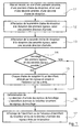
On présente maintenant, en relation avec l'organigramme simplifié de la figure 1, un mode de réalisation particulier du procédé selon l'invention de test d'un réseau de radiocommunication.We now present, in relation to the simplified flowchart of Figure 1, a particular embodiment of the method according to the invention for testing a network of radiocommunication.
Selon l'invention, le procédé comprend les étapes suivantes :
- on met (11) en oeuvre, en aval d'une première antenne, une première chaíne de réception, et en aval d'une seconde antenne, une seconde chaíne de réception distincte de la première chaíne de réception, chaque antenne comprenant un réseau d'éléments rayonnants répartis matriciellement sur un support. A chaque chaíne de réception est associée un faisceau rayonnant radioélectrique de réception propre ;
- on affecte (12) la première chaíne de réception à la réception de premiers signaux, selon une première direction d'arrivée. Ces premiers signaux sont issus d'un premier émetteur situé soit dans la zone géographique couverte par la station de base soit dans un environnement proche, tel que dans une cellule voisine ou à proximité de la station de base concernée ;
- on affecte (13) la seconde chaíne de réception à la réception de seconds signaux, selon une seconde direction d'arrivée. Ces seconds signaux présentent au moins certaines caractéristiques identiques ou similaires à celles utilisées par le premier émetteur. Les seconds signaux sont issus d'un second émetteur situé également soit dans la zone géographique couverte par la station de base soit dans un environnement proche, tel que dans une cellule voisine ou à proximité de la station de base concernée ;
- chaque chaíne de réception tente (14) de décoder les signaux qu'elle reçoit,
- si le décodage de chaque chaíne de réception peut être effectué, de façon complète, chaque chaíne de réception lit (15) un identifiant véhiculé par les signaux et propre à l'émetteur qui les a émis, de façon à déterminer (16) d'une part lesquels des premiers et seconds signaux sont les signaux de brouillage, et d'autre part la direction d'arrivée des signaux de brouillage ainsi que l'identifiant du brouilleur émettant les signaux de brouillage. Cet identifiant est par exemple celui du brouilleur au sein de la cellule dans laquelle l'élément brouilleur se trouve. Cet identifiant est véhiculé par tous les messages transmis par exemple sur les canaux BCCH (pour "Broadcast Control CHannel" en anglais) et BSIC (pour "Base Station Identity Code" en anglais ou "Code d'Identité de la station de base" en français) selon la norme GSM. Dans ce premier cas, le brouilleur appartient au réseau de radiocommunication ;
- si le décodage d'une chaíne de réception n'est pas possible alors on en déduit directement lesquels desdits premiers et seconds signaux sont les signaux utiles (ce sont les signaux ayant pu être décodés) et les signaux de brouillage (ce sont ceux n'ayant pu être décodés). Dans ce second cas, le brouilleur est donc étranger au réseau de radiocommunication, on détermine (16) seulement la direction d'arrivée des signaux de brouillage.
- is implemented (11) downstream of a first antenna, a first reception chain, and downstream of a second antenna, a second reception chain distinct from the first reception chain, each antenna comprising a network of 'radiating elements distributed matrically on a support. Each reception chain is associated with a radio beam of its own reception;
- it assigns (12) the first reception chain to the reception of first signals, in a first direction of arrival. These first signals come from a first transmitter located either in the geographical area covered by the base station or in a close environment, such as in a neighboring cell or near the base station concerned;
- it assigns (13) the second reception chain to the reception of second signals, in a second direction of arrival. These second signals have at least certain characteristics identical or similar to those used by the first transmitter. The second signals come from a second transmitter also located either in the geographical area covered by the base station or in a close environment, such as in a neighboring cell or close to the base station concerned;
- each reception chain tries (14) to decode the signals it receives,
- if the decoding of each reception chain can be carried out, in a complete manner, each reception chain reads (15) an identifier conveyed by the signals and specific to the transmitter which transmitted them, so as to determine (16) d ' on the one hand which of the first and second signals are the interference signals, and on the other hand the direction of arrival of the interference signals as well as the identifier of the jammer transmitting the interference signals. This identifier is for example that of the jammer within the cell in which the jammer element is located. This identifier is conveyed by all messages transmitted for example on the BCCH (for "Broadcast Control CHannel" in English) and BSIC (for "Base Station Identity Code" in English or "Base Station Identity Code" in English) channels. French) according to the GSM standard. In this first case, the jammer belongs to the radiocommunication network;
- if the decoding of a reception chain is not possible then we deduce directly which of said first and second signals are the useful signals (these are the signals that could have been decoded) and the scrambling signals (these are those n ' could have been decoded). In this second case, the jammer is therefore foreign to the radiocommunication network, only the direction of arrival of the interference signals is determined (16).
Dans un mode de réalisation particulier, le procédé comprend, en outre, une étape (17) d'affichage de l'identifiant ou de l'absence d'identifiant du brouilleur et/ou de la direction d'arrivée des signaux de brouillage. Un opérateur qui utilise le procédé de l'invention visualise ainsi la nature du brouilleur et/ou l'origine précise des signaux de brouillage.In a particular embodiment, the method further comprises a step (17) display of the identifier or the absence of an identifier for the jammer and / or the direction of arrival of the interference signals. An operator who uses the the invention thus visualizes the nature of the jammer and / or the precise origin of the interference.
Un tel procédé permet, pour une communication donnée, non seulement de détecter la présence d'un brouilleur dans la cellule associée à la station de base concernée (ou dans un environnement proche de cette cellule), mais également de renseigner l'opérateur sur la zone dans laquelle se trouve le brouilleur. Cette zone englobe notamment la zone couverte par le faisceau rayonnant radioélectrique de réception associé à la chaíne de réception correspondante (c'est-à-dire soit la première soit la seconde chaíne de réception).Such a method allows, for a given communication, not only to detect the presence of a jammer in the cell associated with the base station concerned (or in an environment close to this cell), but also to provide information the operator in the area where the jammer is located. This area includes in particular the area covered by the associated receiving radioelectric beam to the corresponding reception chain (i.e. either the first or the second chain reception).
En fonction de la nature du ou des brouilleur(s) et/ou de la position angulaire du faisceau rayonnant radioélectrique de réception des signaux de brouillage, l'opérateur peut prendre toute(s) mesure(s) appropriée(s) permettant de supprimer l'émission de tels signaux de brouillage. La ou les mesure(s) peu(ven)t consister notamment :
- soit à affecter un ou des nouveau(x) paramètre(s) distinct(s) de ceux utilisés par les communications en cours, dans la station de base concernée ou éventuellement dans une ou des stations de base voisine(s). On notera qu'un tel procédé permet notamment de s'apercevoir, avec précision, des oublis et/ou erreurs commises dans le voisinage de la station de base concernée en WCDMA, qui génèrent par exemple des codes non orthogonaux (et donc des interférences) ;
- soit à prévenir une autorité compétente pour lui signaler un intrus, selon une direction d'arrivée déterminée. L'intrus est, en effet, selon toutes vraisemblances, non autorisé à émettre avec au moins certaine(s) des caractéristiques qu'il utilise, dans la zone dans laquelle il se trouve.
- either to assign one or more new parameter (s) distinct from those used by the communications in progress, in the base station concerned or possibly in one or more neighboring base stations. It will be noted that such a method makes it possible in particular to perceive, with precision, omissions and / or errors committed in the vicinity of the base station concerned in WCDMA, which generate for example non-orthogonal codes (and therefore interference) ;
- or to notify a competent authority to report an intruder, according to a determined direction of arrival. The intruder is, in fact, in all likelihood, not authorized to emit with at least some of the characteristics that he uses, in the area in which he is located.
Suite au(x) mesure(s) prise(s) en fonction notamment de la nature du brouilleur, la qualité de réception par la station de base des signaux utiles émis par la station mobile peut alors être améliorée.Following the measure (s) taken, depending in particular on the nature of the jammer, the reception quality by the base station of the useful signals transmitted by the mobile station can then be improved.
On présente maintenant, en relation avec la vue partiellement en trois dimensions d'un schéma simplifié de la figure 2, une station de base d'un réseau de radiocommunication.We now present, in relation to the partially three-dimensional view of a simplified diagram of FIG. 2, a base station of a network of radiocommunication.
Une station de base 21 est située en un site 20 définissant le centre d'une cellule
donnée qui lui est affectée, dans laquelle elle peut recevoir et émettre des signaux. Un
dispositif 22 de test d'un réseau de radiocommunication est placée sur le même site 20
que celui de la station de base 21, par exemple en l'origine O du repère à trois dimensions
(Ox, Oy, Oz). Un tel dispositif 22 est destiné à mettre en oeuvre le procédé décrit
précédemment, afin de détecter et d'élucider les interférences entre deux émetteurs, à
savoir d'une part une station mobile (MS) 24 émettant des signaux utiles en direction de la
station de base 21 et d'autre part un brouilleur (B) 23 émettant des signaux de brouillage
également en direction de la station de base 21.A
Pour ce faire, le dispositif 22 comprend deux antennes intelligentes directives
310a, 310b tel qu'il est expliqué, en détail, plus loin (cf figure 3).To do this, the
On rappelle qu'une antenne intelligente directive, ou antenne intelligente à adaptation de faisceaux ("Adaptative Smart Antennas"), comprend un réseau d'éléments rayonnants répartis matriciellement sur un support (ou panneau). Le réseau d'éléments rayonnants est composé d'une pluralité de colonnes d'éléments rayonnants, pilotée généralement chacune indépendamment des autres, de façon à former un faisceau selon un azimut donné.Remember that a directive smart antenna, or smart antenna with beam adaptation ("Adaptive Smart Antennas"), includes a network of elements radiant distributed matrically on a support (or panel). The network of elements radiant is composed of a plurality of columns of radiating elements, controlled generally each independently of the others, so as to form a bundle according to a given azimuth.
En jouant, colonne par colonne, sur la phase et la puissance de chacun des
éléments rayonnants, le dispositif 22 de test d'un réseau de radiocommunication pilote les
antennes 310a, 310b, de façon que celles-ci génèrent deux faisceaux 25, 26 rayonnants
radioélectriques directifs, et orientés en azimut, vers la station mobile 24 et l'éventuel
brouilleur 23. En d'autres termes, un premier diagramme 26 de rayonnement de l'antenne
310b est pointé (ou encore focalisé) sur la station mobile 24 en communication et un
second diagramme 25 de rayonnement de l'antenne 310a est pointé sur l'éventuel
brouilleur 23.By playing, column by column, on the phase and the power of each of the
radiating elements, the
Il est à noter que, de façon à encore améliorer la directivité et le gain des antennes
310a, 310b intelligentes comprises dans le dispositif 22 de test d'un réseau de
radiocommunication, on peut prévoir d'orienter les faisceaux 25, 26 rayonnants
radioélectriques, non seulement en azimut, mais aussi en site. Une telle technique est
décrite dans la demande de brevet française n° 98 08782 (non publiée), au nom du même
déposant. Selon cette technique, l'orientation du faisceau de réception est réalisée à la fois
en site et en azimut, au moyen d'une action sur les paramètres de réception de chacun des
éléments rayonnants, différemment l'un par rapport à l'autre.It should be noted that, in order to further improve the directivity and the gain of the
Les faisceaux radioélectriques de réception 25, 26 peuvent donc être orientés en azimut et en site, selon deux couples d'angles (α 1 ; 1) et (α1 ; 2) respectivement, avec α 1 et α 2 les angles d'azimut, et 1 et 2 les angles de site. Les couples d'angles (α 1 ; 1) et (α2 ; 2) représentent deux directions distinctes d'arrivée des signaux utiles et des signaux de brouillage.The radio reception beams 25, 26 can therefore be oriented in azimuth and in elevation, according to two pairs of angles ( α 1 ; 1 ) and (α 1 ; 2 ) respectively, with α 1 and α 2 the angles d 'azimuth, and 1 and 2 the elevation angles. The pairs of angles ( α 1 ; 1 ) and (α 2 ; 2 ) represent two distinct directions of arrival of the wanted signals and the interference signals.
Le brouilleur 23 peut être un élément appartenant au réseau de
radiocommunication qui comprend la station mobile 24 et la station de base 21. Il peut
donc s'agir d'une station mobile ou d'une station de base voisine. Le brouilleur 23 peut
également être un élément étranger au réseau de radiocommunication.The
On cite maintenant, à titre d'exemple, des situations de brouillage classiques selon le type de multiplexage mis en oeuvre par le système de radiocommunication :
- multiplexage fréquentiel (FDMA) : un brouilleur émet sur la fréquence allouée à la
station mobile en cours de communication :
- soit le brouilleur est de nature connue (c'est une station mobile ou une station de base du réseau de radiocommunication) : il émet alors, sur sa fréquence, un identifiant au sein du réseau de radiocommunication ;
- soit le brouilleur ne fait pas partie du réseau de radiocommunication : il n'émet alors pas d'identifiant du réseau de radiocommunication ;
- multiplexage temporel (TDMA) : le brouilleur émet sur l'intervalle de temps alloué à la
station mobile en cours de communication :
- soit le brouilleur appartient au réseau de radiocommunication : il émet alors, pendant son intervalle de temps, un identifiant au sein du réseau de radiocommunication ;
- soit le brouilleur est étranger au réseau de radiocommunication : il n'émet pas d'identifiant ;
- multiplexage par code (CDMA ou WCDMA) : le brouilleur émet dans une bande de
fréquence allouée à la station mobile en cours de communication ou à une fréquence
parasite (c'est-à-dire une fréquence multiple de celle allouée à la station mobile) :
- soit le brouilleur appartient au réseau de radiocommunication : il émet alors, sur un code non orthogonal au code utilisé par la station mobile, un identifiant au sein du réseau de radiocommunication ;
- soit le brouilleur est étranger au réseau de radiocommunication : il n'émet pas avec un code et donc sans identifiant au sein du réseau de radiocommunication.
- Frequency multiplexing (FDMA): a jammer transmits on the frequency allocated to the mobile station during a call:
- either the jammer is of a known nature (it is a mobile station or a base station of the radiocommunication network): it then transmits, on its frequency, an identifier within the radiocommunication network;
- either the jammer is not part of the radiocommunication network: it then does not transmit an identifier of the radiocommunication network;
- Time division multiplexing (TDMA): the jammer transmits over the time interval allocated to the mobile station during a call:
- either the jammer belongs to the radiocommunication network: it then transmits, during its time interval, an identifier within the radiocommunication network;
- or the jammer is foreign to the radiocommunication network: it does not emit an identifier;
- code multiplexing (CDMA or WCDMA): the jammer transmits in a frequency band allocated to the mobile station during the call or at a spurious frequency (i.e. a frequency multiple of that allocated to the mobile station) :
- either the jammer belongs to the radiocommunication network: it then transmits, on a code not orthogonal to the code used by the mobile station, an identifier within the radiocommunication network;
- or the jammer is foreign to the radiocommunication network: it does not transmit with a code and therefore without an identifier within the radiocommunication network.
Comme présenté sur le schéma simplifié de la figure 3, dans un mode de réalisation particulier, le dispositif 22 selon l'invention de test d'un réseau de radiocommunication comprend :
- une première et une seconde antennes 310a, 310b comprenant chacune un réseau
d'éléments rayonnants 32a, 32b répartis matriciellement sur
un support - en aval de la première antenne 310a, une première chaíne de réception 31a comprenant des premiers moyens 312a de réception, et en aval de la seconde antenne 310b, une seconde chaíne de réception 31b distincte de la première chaíne de réception 31a et comprenant des seconds moyens 312b de réception. Ces premiers et seconds moyens 312a et 312b de réception sont connus en soi et assurent le traitement radio des signaux reçus par leur antenne respective (classiquement sommation des différentes contributions, amplification, filtrage, transfert en bande de base, conversion analogique/numérique, maximisation de la réception du signal par l'obtention d'un niveau de puissance de réception maximum et/ou d'un taux d'erreur binaire minimum (ou "Binary Error Rate"en anglais)...) ;
- des moyens 311a d'affectation de la première chaíne de réception 31a à la réception de premiers signaux, selon une première direction d'arrivée (α1 ; 1) avec α1 l'angle d'azimut et 1 l'angle de site. La détermination de la première direction d'arrivée peut s'effectuer à partir des déphasages relatifs observés entre les différents éléments rayonnants ;
- des moyens 311b d'affectation de la seconde chaíne de réception 31b à la réception de seconds signaux, selon une seconde direction d'arrivée (α2 ; 2) avec α2 l'angle d'azimut et 2 l'angle de site. La détermination de la seconde direction d'arrivée peut également s'effectuer à partir des déphasages relatifs observés entre les différents éléments rayonnants ;
- des moyens 313a, 313b de décodage des signaux reçus par chacune des chaínes de réception 31a, 31b. Ces moyens 313a, 313b permettent de décoder les premiers et seconds signaux, de façon à retrouver les messages transmis par ces derniers ;
- des moyens 314a, 314b de lecture, placés en aval des moyens 313a, 313b de décodage, de façon à lire un identifiant véhiculé par les signaux et propre à l'émetteur qui les a émis. C'est cet identifiant qui renseigne sur la nature des émetteurs (la station mobile 24 en cours de communication et le brouilleur 23) ;
- des moyens 315a, 315b de prise de décision, permettant, en fonction de signaux de sortie des moyens 313a, 313b de décodage et 314a, 314b de lecture, de déterminer d'une part lesquels des premiers et seconds signaux sont les signaux de brouillage, et d'autre part la direction d'arrivée des signaux de brouillage et/ou l'identifiant éventuel du brouilleur 23 émettant les signaux de brouillage.
- first and
second antennas elements support antennas mobile station 24 and apossible jammer 23, when these move within the geographical area covered by the twoantennas - downstream of the
first antenna 310a, afirst reception chain 31a comprising first reception means 312a, and downstream of thesecond antenna 310b, asecond reception chain 31b distinct from thefirst reception chain 31a and comprising second means 312b of receipt. These first and second reception means 312a and 312b are known per se and ensure the radio processing of the signals received by their respective antenna (conventionally summation of the different contributions, amplification, filtering, transfer in baseband, analog / digital conversion, maximization of signal reception by obtaining a maximum reception power level and / or a minimum binary error rate (or "Binary Error Rate"...); - means 311a for assigning the
first reception chain 31a to the reception of first signals, in a first direction of arrival (α 1 ; 1 ) with α 1 the azimuth angle and 1 the angle of site. The determination of the first direction of arrival can be carried out from the relative phase shifts observed between the different radiating elements; - means 311b for assigning the
second reception chain 31b to the reception of second signals, in a second direction of arrival (α 2 ; 2 ) with α 2 the azimuth angle and 2 the angle of site. The determination of the second direction of arrival can also be carried out from the relative phase shifts observed between the different radiating elements; - means 313a, 313b for decoding the signals received by each of the
reception chains means - means 314a, 314b for reading, placed downstream from the
means mobile station 24 during communication and the jammer 23); - decision-making means 315a, 315b, making it possible, on the basis of output signals from the decoding means 313a, 313b and 314a, 314b to read, on the one hand which of the first and second signals are the interference signals, and on the other hand the direction of arrival of the jamming signals and / or the possible identifier of the
jammer 23 transmitting the jamming signals.
Le dispositif 22 comprend en outre des moyens 34 d'affichage de l'identifiant ou
de l'absence d'identifiant du brouilleur 23 et/ou de la direction d'arrivée des signaux de
brouillage. Un opérateur 35 peut consulter les résultats de la recherche de brouilleur(s)
pour une communication donnée entre la station mobile 24 et la station de base 21 qui
utilise le dispositif 21 décrit ci-dessus.The
Dans le cas où le brouilleur appartient au réseau de radiocommunication,
l'opérateur 35 peut, dès qu'il en est informé (par exemple par affichage), modifier le ou
les paramètre(s) de communication correspondant(s) pour supprimer les interférences. Il
peut notamment s'agir d'une intervention au niveau d'une station de base voisine
présentant une anomalie ou d'une station mobile défectueuse dont certaines
caractéristiques (et notamment celles influant sur les signaux échangés) sont à modifier.If the jammer belongs to the radiocommunication network,
the
Dans le cas où le brouilleur n'appartient pas au réseau de radiocommunication, l'information dont on dispose concernant le brouilleur (à savoir sa position angulaire par rapport à la station de base) peut être communiquée aux autorités compétentes (comités d'attribution des ressources, police, etc...), afin que ces dernières retrouvent le propriétaire du brouilleur et fassent cesser le trouble qu'il occasionne.If the jammer does not belong to the radiocommunication network, the information available on the jammer (i.e. its angular position by report to the base station) can be communicated to the competent authorities (committees allocation of resources, police, etc.), so that they find the owner of the jammer and put an end to the disturbance it causes.
Selon une variante de réalisation, le dispositif 22 de test d'un réseau de
radiocommunication décrit ci-dessus est compris dans la station de base 21 du réseau de
radiocommunication, et réutilise une partie des moyens constitutifs de cette dernière.According to an alternative embodiment, the
En effet, si l'on suppose que la station de base est du type mettant en oeuvre un
multiplexage spatial (ou "SDMA" pour "Spatial Division Multiple Access" en anglais ou
"Accès Multiple à Répartition dans l'Espace" en français), alors elle utilise notamment un
faisceau rayonnant radioélectrique de réception directif et orientable à l'aide de moyens
électroniques, de façon à "suivre" la station mobile lors de son déplacement au sein de la
cellule, pour communiquer avec elle. La station de base comprend donc au moins une
première antenne 310a intelligente directive et une chaíne de réception 3 la tels que décrits
précédemment, pour communiquer avec la station mobile en cours de communication.
Ainsi, il suffit d'ajouter une seconde antenne intelligente directive et une seconde chaíne
de réception entière à la station de base, sauf si certains moyens (notamment de décodage
et/ou de lecture) de cette seconde chaíne peuvent être partagés avec le dispositif de test
d'un réseau de radiocommunication. Indeed, if we assume that the base station is of the type implementing a
spatial multiplexing (or "SDMA" for "Spatial Division Multiple Access" in English or
"Multiple Access to Distribution in Space" in French), so it uses in particular a
radioelectric receiving beam directional and orientable using means
electronic, so as to "follow" the mobile station during its movement within the
cell, to communicate with her. The base station therefore comprises at least one
first
Par contre, si l'on suppose que la station de base n'est pas du type mettant en oeuvre un multiplexage spatial, et met en oeuvre par exemple un multiplexage fréquentiel (ou FDMA) ou un multiplexage temporel (ou TDMA) ou encore par code (ou CDMA), alors il est nécessaire pour construire le dispositif de test selon l'invention de prévoir au moins deux antennes intelligentes supplémentaires ainsi qu'au moins une partie des différentes chaínes de réception (notamment des moyens d'affectation des différentes chaínes de réception, des moyens de décodage et des moyens de prise de décision).On the other hand, if we assume that the base station is not of the type setting up performs spatial multiplexing, and implements for example frequency multiplexing (or FDMA) or a time division multiplexing (or TDMA) or even by code (or CDMA), then it is necessary to build the test device according to the invention to provide at at least two additional smart antennas and at least some of the different reception chains (in particular means of allocation of the different reception channels, decoding means and decision-making means).
Claims (7)
caractérisé en ce qu'il comprend les étapes suivantes :
characterized in that it comprises the following stages:
caractérisé en ce qu'il comprend :
characterized in that it comprises:
caractérisé en ce qu'elle comprend un dispositif (22) de test d'un réseau de radiocommunication selon la revendication 6.Base station (21) of a radiocommunication system making it possible to detect and elucidate interference between at least two transmitters, namely on the one hand a mobile station (23) transmitting useful signals towards said base station (21), and on the other hand at least one jammer (23) transmitting jamming signals also in the direction of said base station (21),
characterized in that it comprises a device (22) for testing a radiocommunication network according to claim 6.
Applications Claiming Priority (2)
| Application Number | Priority Date | Filing Date | Title |
|---|---|---|---|
| FR9810846A FR2782882B1 (en) | 1998-08-26 | 1998-08-26 | METHOD FOR TESTING A RADIO COMMUNICATION NETWORK, CORRESPONDING DEVICE AND STATION |
| FR9810846 | 1998-08-26 |
Publications (2)
| Publication Number | Publication Date |
|---|---|
| EP0982960A1 true EP0982960A1 (en) | 2000-03-01 |
| EP0982960B1 EP0982960B1 (en) | 2006-07-12 |
Family
ID=9529976
Family Applications (1)
| Application Number | Title | Priority Date | Filing Date |
|---|---|---|---|
| EP99460053A Expired - Lifetime EP0982960B1 (en) | 1998-08-26 | 1999-08-25 | Radiocommunication network test procedure and corresponding device and base station |
Country Status (6)
| Country | Link |
|---|---|
| US (1) | US6487245B1 (en) |
| EP (1) | EP0982960B1 (en) |
| AT (1) | ATE333196T1 (en) |
| DE (1) | DE69932295T2 (en) |
| ES (1) | ES2268840T3 (en) |
| FR (1) | FR2782882B1 (en) |
Families Citing this family (3)
| Publication number | Priority date | Publication date | Assignee | Title |
|---|---|---|---|---|
| US7043259B1 (en) * | 2000-09-29 | 2006-05-09 | Arraycomm, Inc. | Repetitive paging from a wireless data base station having a smart antenna system |
| US6795409B1 (en) * | 2000-09-29 | 2004-09-21 | Arraycomm, Inc. | Cooperative polling in a wireless data communication system having smart antenna processing |
| JP4159273B2 (en) * | 2001-09-13 | 2008-10-01 | アルパイン株式会社 | Broadcast receiving apparatus and channel scanning method |
Citations (1)
| Publication number | Priority date | Publication date | Assignee | Title |
|---|---|---|---|---|
| EP0647978A2 (en) * | 1993-08-12 | 1995-04-12 | Nortel Networks Corporation | Base station antenna arrangement |
Family Cites Families (7)
| Publication number | Priority date | Publication date | Assignee | Title |
|---|---|---|---|---|
| US4584716A (en) * | 1984-11-13 | 1986-04-22 | Honeywell Inc. | Automatic dual diversity receiver |
| JP3033308B2 (en) * | 1991-12-25 | 2000-04-17 | 松下電器産業株式会社 | Synthetic diversity receiver |
| US5325403A (en) * | 1992-12-09 | 1994-06-28 | Motorola, Inc. | Method and apparatus for dual-channel diversity reception of a radio signal |
| US6173014B1 (en) * | 1994-08-02 | 2001-01-09 | Telefonaktiebolaget Lm Ericsson | Method of and apparatus for interference rejection combining and downlink beamforming in a cellular radio communications system |
| JPH10247869A (en) * | 1997-03-04 | 1998-09-14 | Nec Corp | Diversity circuit |
| US6108389A (en) * | 1997-12-11 | 2000-08-22 | Motorola, Inc. | Synchronization of internal coder-decoders of multiple microprocessors |
| US6236844B1 (en) * | 1998-06-23 | 2001-05-22 | Visteon Global Technologies, Inc. | Proportional diversity radio receiver system |
-
1998
- 1998-08-26 FR FR9810846A patent/FR2782882B1/en not_active Expired - Fee Related
-
1999
- 1999-08-25 EP EP99460053A patent/EP0982960B1/en not_active Expired - Lifetime
- 1999-08-25 US US09/383,024 patent/US6487245B1/en not_active Expired - Lifetime
- 1999-08-25 AT AT99460053T patent/ATE333196T1/en not_active IP Right Cessation
- 1999-08-25 ES ES99460053T patent/ES2268840T3/en not_active Expired - Lifetime
- 1999-08-25 DE DE69932295T patent/DE69932295T2/en not_active Expired - Lifetime
Patent Citations (1)
| Publication number | Priority date | Publication date | Assignee | Title |
|---|---|---|---|---|
| EP0647978A2 (en) * | 1993-08-12 | 1995-04-12 | Nortel Networks Corporation | Base station antenna arrangement |
Also Published As
| Publication number | Publication date |
|---|---|
| EP0982960B1 (en) | 2006-07-12 |
| FR2782882B1 (en) | 2000-10-20 |
| ATE333196T1 (en) | 2006-08-15 |
| FR2782882A1 (en) | 2000-03-03 |
| US6487245B1 (en) | 2002-11-26 |
| DE69932295D1 (en) | 2006-08-24 |
| ES2268840T3 (en) | 2007-03-16 |
| DE69932295T2 (en) | 2007-07-19 |
Similar Documents
| Publication | Publication Date | Title |
|---|---|---|
| RU2155460C2 (en) | Antenna with wide lobe of directivity pattern | |
| US8223733B2 (en) | Multi-platform wireless communication system for a variety of different user types | |
| EP0960451B1 (en) | Method and apparatus for directional radio communication | |
| US9853668B2 (en) | Wideband beamformer system | |
| EP2567472B1 (en) | Terrestrial-satellite hybrid system for high capacity cellular wireless communications | |
| JPH08510609A (en) | Cellular / satellite communication system with improved frequency reuse | |
| FR2757004A1 (en) | METHOD AND SYSTEM FOR OPTIMIZING A TRAFFIC CHANNEL IN A WIRELESS COMMUNICATION SYSTEM | |
| KR20070013297A (en) | Systems and methods for space-based reuse of terrestrial cellular frequency spectrum | |
| FR2655220A1 (en) | ZONE COMMUNICATION SYSTEM. | |
| KR19990082079A (en) | Method and apparatus of cellular radiotelephone base station using selected multiple diversity reception | |
| FR2677198A1 (en) | METHOD AND DEVICE FOR IMPROVING THE QUALITY OF A TELECOMMUNICATION SIGNAL | |
| Poole | Cellular communications explained: from basics to 3G | |
| EP0977380A1 (en) | Cellular radiocommunications system employing a data repetition downwards from a base station and data repeater therefor | |
| US6748216B1 (en) | Method and apparatus for intelligent microcell and antenna selection in digital cellular telephone systems | |
| EP0982960B1 (en) | Radiocommunication network test procedure and corresponding device and base station | |
| EP0971438A1 (en) | Method for directing radiating beams for the communication between a base station and a mobile radio telephone and base station therefor | |
| WO2020079259A1 (en) | Satellite communications system and method for transmitting a bit stream therewith | |
| EP1253799A1 (en) | A method and arrangement for locating a mobile station in a communications network | |
| CN1172459C (en) | Apparatus and method for sending common information on common data channels | |
| US20040248512A1 (en) | Satellite communication method and system | |
| RU2227371C2 (en) | High-efficiency and high-altitude suborbital telecommunication system and method for establishing wireless telecommunications | |
| EP0865220A1 (en) | Method of configuring cells in a digital cellular radiocommunication system | |
| EP1000445B1 (en) | Antenna network for base station radiocommunication with mobile telephones | |
| EP0767550A1 (en) | Interband frequency hopping system for cellular radio communication system with mobile stations, and stations therefor | |
| EP3506527B1 (en) | Method for managing a communication network and associated communication network |
Legal Events
| Date | Code | Title | Description |
|---|---|---|---|
| PUAI | Public reference made under article 153(3) epc to a published international application that has entered the european phase |
Free format text: ORIGINAL CODE: 0009012 |
|
| AK | Designated contracting states |
Kind code of ref document: A1 Designated state(s): AT BE CH CY DE DK ES FI FR GB GR IE IT LI LU MC NL PT SE |
|
| AX | Request for extension of the european patent |
Free format text: AL;LT;LV;MK;RO;SI |
|
| 17P | Request for examination filed |
Effective date: 20000608 |
|
| AKX | Designation fees paid |
Free format text: AT BE CH CY DE DK ES FI FR GB GR IE IT LI LU MC NL PT SE |
|
| 17Q | First examination report despatched |
Effective date: 20040112 |
|
| RAP1 | Party data changed (applicant data changed or rights of an application transferred) |
Owner name: COMPAGNIE FINANCIERE POUR LE RADIOTELEPHONE SA |
|
| RAP1 | Party data changed (applicant data changed or rights of an application transferred) |
Owner name: CEGETEL GROUPE |
|
| RAP1 | Party data changed (applicant data changed or rights of an application transferred) |
Owner name: SOCIETE FRANEAISE DU RADIOTELEPHONE-SFR |
|
| GRAP | Despatch of communication of intention to grant a patent |
Free format text: ORIGINAL CODE: EPIDOSNIGR1 |
|
| GRAS | Grant fee paid |
Free format text: ORIGINAL CODE: EPIDOSNIGR3 |
|
| GRAA | (expected) grant |
Free format text: ORIGINAL CODE: 0009210 |
|
| AK | Designated contracting states |
Kind code of ref document: B1 Designated state(s): AT BE CH CY DE DK ES FI FR GB GR IE IT LI LU MC NL PT SE |
|
| PG25 | Lapsed in a contracting state [announced via postgrant information from national office to epo] |
Ref country code: NL Free format text: LAPSE BECAUSE OF FAILURE TO SUBMIT A TRANSLATION OF THE DESCRIPTION OR TO PAY THE FEE WITHIN THE PRESCRIBED TIME-LIMIT Effective date: 20060712 Ref country code: IE Free format text: LAPSE BECAUSE OF FAILURE TO SUBMIT A TRANSLATION OF THE DESCRIPTION OR TO PAY THE FEE WITHIN THE PRESCRIBED TIME-LIMIT Effective date: 20060712 Ref country code: FI Free format text: LAPSE BECAUSE OF FAILURE TO SUBMIT A TRANSLATION OF THE DESCRIPTION OR TO PAY THE FEE WITHIN THE PRESCRIBED TIME-LIMIT Effective date: 20060712 Ref country code: AT Free format text: LAPSE BECAUSE OF FAILURE TO SUBMIT A TRANSLATION OF THE DESCRIPTION OR TO PAY THE FEE WITHIN THE PRESCRIBED TIME-LIMIT Effective date: 20060712 |
|
| REG | Reference to a national code |
Ref country code: GB Ref legal event code: FG4D Free format text: NOT ENGLISH |
|
| REG | Reference to a national code |
Ref country code: CH Ref legal event code: EP |
|
| REG | Reference to a national code |
Ref country code: IE Ref legal event code: FG4D Free format text: LANGUAGE OF EP DOCUMENT: FRENCH |
|
| REF | Corresponds to: |
Ref document number: 69932295 Country of ref document: DE Date of ref document: 20060824 Kind code of ref document: P |
|
| PG25 | Lapsed in a contracting state [announced via postgrant information from national office to epo] |
Ref country code: SE Free format text: LAPSE BECAUSE OF FAILURE TO SUBMIT A TRANSLATION OF THE DESCRIPTION OR TO PAY THE FEE WITHIN THE PRESCRIBED TIME-LIMIT Effective date: 20061012 Ref country code: DK Free format text: LAPSE BECAUSE OF FAILURE TO SUBMIT A TRANSLATION OF THE DESCRIPTION OR TO PAY THE FEE WITHIN THE PRESCRIBED TIME-LIMIT Effective date: 20061012 |
|
| REG | Reference to a national code |
Ref country code: CH Ref legal event code: NV Representative=s name: E. BLUM & CO. PATENTANWAELTE |
|
| GBT | Gb: translation of ep patent filed (gb section 77(6)(a)/1977) |
Effective date: 20061012 |
|
| PG25 | Lapsed in a contracting state [announced via postgrant information from national office to epo] |
Ref country code: PT Free format text: LAPSE BECAUSE OF FAILURE TO SUBMIT A TRANSLATION OF THE DESCRIPTION OR TO PAY THE FEE WITHIN THE PRESCRIBED TIME-LIMIT Effective date: 20061212 |
|
| NLV1 | Nl: lapsed or annulled due to failure to fulfill the requirements of art. 29p and 29m of the patents act | ||
| REG | Reference to a national code |
Ref country code: ES Ref legal event code: FG2A Ref document number: 2268840 Country of ref document: ES Kind code of ref document: T3 |
|
| PLBE | No opposition filed within time limit |
Free format text: ORIGINAL CODE: 0009261 |
|
| STAA | Information on the status of an ep patent application or granted ep patent |
Free format text: STATUS: NO OPPOSITION FILED WITHIN TIME LIMIT |
|
| 26N | No opposition filed |
Effective date: 20070413 |
|
| REG | Reference to a national code |
Ref country code: CH Ref legal event code: PFA Owner name: SOCIETE FRANCAISE DU RADIOTELEPHONE-SFR Free format text: SOCIETE FRANCAISE DU RADIOTELEPHONE-SFR#42, AVENUE DE FRIEDLAND#75008 PARIS (FR) -TRANSFER TO- SOCIETE FRANCAISE DU RADIOTELEPHONE-SFR#42, AVENUE DE FRIEDLAND#75008 PARIS (FR) |
|
| REG | Reference to a national code |
Ref country code: HK Ref legal event code: WD Ref document number: 1026995 Country of ref document: HK |
|
| PG25 | Lapsed in a contracting state [announced via postgrant information from national office to epo] |
Ref country code: GR Free format text: LAPSE BECAUSE OF FAILURE TO SUBMIT A TRANSLATION OF THE DESCRIPTION OR TO PAY THE FEE WITHIN THE PRESCRIBED TIME-LIMIT Effective date: 20061013 |
|
| PG25 | Lapsed in a contracting state [announced via postgrant information from national office to epo] |
Ref country code: CY Free format text: LAPSE BECAUSE OF FAILURE TO SUBMIT A TRANSLATION OF THE DESCRIPTION OR TO PAY THE FEE WITHIN THE PRESCRIBED TIME-LIMIT Effective date: 20060712 |
|
| REG | Reference to a national code |
Ref country code: FR Ref legal event code: GC Effective date: 20150310 |
|
| REG | Reference to a national code |
Ref country code: FR Ref legal event code: PLFP Year of fee payment: 18 |
|
| REG | Reference to a national code |
Ref country code: FR Ref legal event code: PLFP Year of fee payment: 19 |
|
| REG | Reference to a national code |
Ref country code: FR Ref legal event code: GC Effective date: 20180111 |
|
| REG | Reference to a national code |
Ref country code: FR Ref legal event code: PLFP Year of fee payment: 20 |
|
| PGFP | Annual fee paid to national office [announced via postgrant information from national office to epo] |
Ref country code: LU Payment date: 20180724 Year of fee payment: 20 |
|
| PGFP | Annual fee paid to national office [announced via postgrant information from national office to epo] |
Ref country code: DE Payment date: 20180719 Year of fee payment: 20 Ref country code: IT Payment date: 20180719 Year of fee payment: 20 Ref country code: ES Payment date: 20180903 Year of fee payment: 20 Ref country code: FR Payment date: 20180720 Year of fee payment: 20 Ref country code: MC Payment date: 20180726 Year of fee payment: 20 |
|
| PGFP | Annual fee paid to national office [announced via postgrant information from national office to epo] |
Ref country code: GB Payment date: 20180720 Year of fee payment: 20 Ref country code: BE Payment date: 20180724 Year of fee payment: 20 Ref country code: CH Payment date: 20180726 Year of fee payment: 20 |
|
| REG | Reference to a national code |
Ref country code: DE Ref legal event code: R071 Ref document number: 69932295 Country of ref document: DE |
|
| REG | Reference to a national code |
Ref country code: CH Ref legal event code: PL |
|
| REG | Reference to a national code |
Ref country code: GB Ref legal event code: PE20 Expiry date: 20190824 |
|
| REG | Reference to a national code |
Ref country code: BE Ref legal event code: MK Effective date: 20190825 |
|
| PG25 | Lapsed in a contracting state [announced via postgrant information from national office to epo] |
Ref country code: GB Free format text: LAPSE BECAUSE OF EXPIRATION OF PROTECTION Effective date: 20190824 |
|
| REG | Reference to a national code |
Ref country code: ES Ref legal event code: FD2A Effective date: 20201002 |
|
| PG25 | Lapsed in a contracting state [announced via postgrant information from national office to epo] |
Ref country code: ES Free format text: LAPSE BECAUSE OF EXPIRATION OF PROTECTION Effective date: 20190826 |