EP0982584B1 - Spectrometer accessory for carrying out attenuated total reflectance measurements - Google Patents
Spectrometer accessory for carrying out attenuated total reflectance measurements Download PDFInfo
- Publication number
- EP0982584B1 EP0982584B1 EP98306956A EP98306956A EP0982584B1 EP 0982584 B1 EP0982584 B1 EP 0982584B1 EP 98306956 A EP98306956 A EP 98306956A EP 98306956 A EP98306956 A EP 98306956A EP 0982584 B1 EP0982584 B1 EP 0982584B1
- Authority
- EP
- European Patent Office
- Prior art keywords
- crystal
- accessory
- mirror
- optical elements
- accessory according
- Prior art date
- Legal status (The legal status is an assumption and is not a legal conclusion. Google has not performed a legal analysis and makes no representation as to the accuracy of the status listed.)
- Expired - Lifetime
Links
- 238000005259 measurement Methods 0.000 title claims description 12
- 238000005102 attenuated total reflection Methods 0.000 title description 9
- 239000013078 crystal Substances 0.000 claims description 69
- 230000003287 optical effect Effects 0.000 claims description 26
- 230000005855 radiation Effects 0.000 claims description 25
- 238000011835 investigation Methods 0.000 claims description 6
- 238000013500 data storage Methods 0.000 claims description 4
- 230000003213 activating effect Effects 0.000 claims 1
- 239000007787 solid Substances 0.000 description 6
- 210000003414 extremity Anatomy 0.000 description 4
- 238000004458 analytical method Methods 0.000 description 3
- 238000000034 method Methods 0.000 description 3
- 238000012545 processing Methods 0.000 description 3
- 230000003595 spectral effect Effects 0.000 description 3
- 239000007767 bonding agent Substances 0.000 description 2
- 239000007788 liquid Substances 0.000 description 2
- 210000003813 thumb Anatomy 0.000 description 2
- 238000005033 Fourier transform infrared spectroscopy Methods 0.000 description 1
- 239000004809 Teflon Substances 0.000 description 1
- 229920006362 Teflon® Polymers 0.000 description 1
- XAGFODPZIPBFFR-UHFFFAOYSA-N aluminium Chemical compound [Al] XAGFODPZIPBFFR-UHFFFAOYSA-N 0.000 description 1
- 229910052782 aluminium Inorganic materials 0.000 description 1
- 239000004411 aluminium Substances 0.000 description 1
- 230000002238 attenuated effect Effects 0.000 description 1
- 238000001210 attenuated total reflectance infrared spectroscopy Methods 0.000 description 1
- 238000005452 bending Methods 0.000 description 1
- 239000011248 coating agent Substances 0.000 description 1
- 238000000576 coating method Methods 0.000 description 1
- 238000004891 communication Methods 0.000 description 1
- 230000006835 compression Effects 0.000 description 1
- 238000007906 compression Methods 0.000 description 1
- 238000009429 electrical wiring Methods 0.000 description 1
- 230000035515 penetration Effects 0.000 description 1
- 229920001343 polytetrafluoroethylene Polymers 0.000 description 1
- 239000004810 polytetrafluoroethylene Substances 0.000 description 1
- 238000004611 spectroscopical analysis Methods 0.000 description 1
- 238000001228 spectrum Methods 0.000 description 1
- 230000001360 synchronised effect Effects 0.000 description 1
Images


Classifications
-
- G—PHYSICS
- G01—MEASURING; TESTING
- G01N—INVESTIGATING OR ANALYSING MATERIALS BY DETERMINING THEIR CHEMICAL OR PHYSICAL PROPERTIES
- G01N21/00—Investigating or analysing materials by the use of optical means, i.e. using sub-millimetre waves, infrared, visible or ultraviolet light
- G01N21/17—Systems in which incident light is modified in accordance with the properties of the material investigated
- G01N21/55—Specular reflectivity
- G01N21/552—Attenuated total reflection
-
- G—PHYSICS
- G01—MEASURING; TESTING
- G01J—MEASUREMENT OF INTENSITY, VELOCITY, SPECTRAL CONTENT, POLARISATION, PHASE OR PULSE CHARACTERISTICS OF INFRARED, VISIBLE OR ULTRAVIOLET LIGHT; COLORIMETRY; RADIATION PYROMETRY
- G01J3/00—Spectrometry; Spectrophotometry; Monochromators; Measuring colours
- G01J3/02—Details
- G01J3/0202—Mechanical elements; Supports for optical elements
-
- G—PHYSICS
- G01—MEASURING; TESTING
- G01J—MEASUREMENT OF INTENSITY, VELOCITY, SPECTRAL CONTENT, POLARISATION, PHASE OR PULSE CHARACTERISTICS OF INFRARED, VISIBLE OR ULTRAVIOLET LIGHT; COLORIMETRY; RADIATION PYROMETRY
- G01J3/00—Spectrometry; Spectrophotometry; Monochromators; Measuring colours
- G01J3/02—Details
- G01J3/0205—Optical elements not provided otherwise, e.g. optical manifolds, diffusers, windows
- G01J3/0208—Optical elements not provided otherwise, e.g. optical manifolds, diffusers, windows using focussing or collimating elements, e.g. lenses or mirrors; performing aberration correction
-
- G—PHYSICS
- G01—MEASURING; TESTING
- G01J—MEASUREMENT OF INTENSITY, VELOCITY, SPECTRAL CONTENT, POLARISATION, PHASE OR PULSE CHARACTERISTICS OF INFRARED, VISIBLE OR ULTRAVIOLET LIGHT; COLORIMETRY; RADIATION PYROMETRY
- G01J3/00—Spectrometry; Spectrophotometry; Monochromators; Measuring colours
- G01J3/02—Details
- G01J3/0205—Optical elements not provided otherwise, e.g. optical manifolds, diffusers, windows
- G01J3/021—Optical elements not provided otherwise, e.g. optical manifolds, diffusers, windows using plane or convex mirrors, parallel phase plates, or particular reflectors
-
- G—PHYSICS
- G01—MEASURING; TESTING
- G01J—MEASUREMENT OF INTENSITY, VELOCITY, SPECTRAL CONTENT, POLARISATION, PHASE OR PULSE CHARACTERISTICS OF INFRARED, VISIBLE OR ULTRAVIOLET LIGHT; COLORIMETRY; RADIATION PYROMETRY
- G01J3/00—Spectrometry; Spectrophotometry; Monochromators; Measuring colours
- G01J3/02—Details
- G01J3/0205—Optical elements not provided otherwise, e.g. optical manifolds, diffusers, windows
- G01J3/0237—Adjustable, e.g. focussing
Definitions
- This invention relates to an accessory which can be used with a spectrometer in order to carry out attenuated total reflectance (ATR) measurements.
- the invention relates to an accessory which can carry out horizontal attenuated total reflectance (HATR) measurements using a crystal in which multiple reflections of the analysing radiation occur.
- ATR attenuated total reflectance
- One known type of crystal is an elongate crystal of generally trapezoidal shape which is used to carry out what is commonly known as horizontal attenuated total reflectance measurements.
- a crystal analysing radiation enters the crystal through one of its inclined end faces and undergoes multiple internal reflections along the length of the crystal before exiting the crystal through its other inclined face.
- Such a crystal can be used to carry out an analysis of both solids and liquids.
- the sample under investigation is placed in close contact with one of the plane surfaces of the crystal and the analysing radiation slightly penetrates the sample at its point of contact with the crystal as the radiation undergoes multiple reflections along the length of the crystal.
- WO 86/06834A describes a refractometer in which the angle of incidence of a beam incident on a hemicylinder and the angle of the reflected beam can be adjusted by independently rotatable mirrors.
- US 5210418 describes an analyser for internal reflection spectroscopy in which the path of the beam includes one plane mirror which is adjustable in tilt and height and a number of fixed mirrors.
- the present invention is concerned with an accessory for carrying out horizontal attenuated total reflection measurements in which optical elements can be adjusted automatically when a change of crystal is required.
- an arrangement in which a reliably reproducible force can be applied to the crystal or sample to maintain contact between the crystal and the sample under investigation.
- an accessory for use with a spectrometer which has a sample station in which the accessory can be located, said accessory comprising a mounting for receiving an ATR crystal, first optical elements for directing an incoming beam of analysing radiation to said crystal and second optical elements for directing a beam of radiation exiting the crystal to an outlet, at least one of the first optical elements and at least one of the second optical elements being pivotable, and the accessory includes means operable to cause pivoting movement of said pivotable elements so that the beam of analysing radiation is caused to be incident on said crystal at an angle appropriate for particular crystal employed or the measurement to be made, wherein the first optical elements include a first mirror fixed to a first plate which is pivotally mounted relative to the housing of the accessory, and the second optical element includes a second pivotable mirror mounted on a second plate which is pivotally mounted relative to the housing of the accessory, characterised in that the pivoting means comprise a rotatable cam member disposed at least partially between and in contact with said plates.
- the cam member may include a plurality of
- the cam member may be rotatable by a motor.
- the motor may be a stepper motor.
- the first mirror may be a toroidal mirror and the second mirror may be a planar mirror.
- the accessory may include electrical connectors which when the accessory is located in the sample station make contact with a connector on the spectrometer and the crystal it may have incorporated therein a data storage medium in which is stored data indicative of the crystal, the arrangement being such that when the accessory is located in the sample station the processor of the spectrometer can read said stored data and can transmit energising signals to said motor to cause the pivotable mirrors to be adjusted to a position appropriate to the crystal.
- the first optical elements may also include a fixed plane mirror and a fixed toroid/ellipsoidal mirror
- the second optical elements may also include a fixed toroidal/ellipsoidal mirror and a fixed planar mirror.
- the accessory may include an arm mounted on said housing, said arm including pressing means contactable with said crystal or a sample located adjacent said crystal in order to apply pressure to said crystal to maintain contact between the crystal and a sample under investigation.
- Pressure measuring means may be associated with said arm.
- the pressure measuring means may comprise a strain gauge.
- the strain gauge may be electrically connectable to said processor of said spectrometer in order to enable data relating to the applied pressure to be transmitted to said processor.
- a display means may be provided to display the sensed pressure thereby enabling an operator to accurately set the optical pressure.
- a spectrometer with which the present accessory can be employed has a housing 10 which accommodates the operative elements of the spectrometer. These include a source of infra-red radiation, a detector capable of detecting infra-red radiation and data processing means for processing signals received from the detector to provide output spectral data relating to the sample under analysis.
- the spectrometer can also have an associated PC (not shown) which provides a user interface and which can receive the output data and carry out processing of that data to provide spectral information.
- the housing 10 includes two forwardly projecting limbs 11 and 12 which define there between a sample station 14.
- each limb (11,12) includes a window 15 through which analysing can pass.
- the present accessory to be described below is locatable in the sample station 14 so that analysing radiation emitted through the window 15 in limb 11, passes to the accessory, is directed along a path to an HATR crystal in the accessory and then exit the accessory, to be received through another window 15 on the opposite limb 12 of the spectrometer where it is received by a detector.
- the spectrometer shown in Figure 1 includes an electrical connector which can connect to an accessory located in the sample station to enable electrical signals to be transferred between the accessory and the processor of the spectrometer.
- the way in which this operation functions is not at the heart of the present invention but is described in more detail in European Patent Application No. 98300745.1.
- an accessory for carrying out a HATR measurements has a housing 20 which accommodates a number of optical elements to be described below.
- Each upright side wall of the housing has an aperture 21,22, the aperture 21 when the accessory is placed in the sample station 14 allowing radiation from the radiation source of the spectrometer to pass into the accessory and the aperture 27 allowing radiation to exit from the accessory towards the detector of the spectrometer.
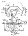
- Figure 3 illustrates the principal optical elements located within the housing 20 of the accessory.
- the optical elements include input optical elements comprising an input concave toroid mirror 25 which is pivotably mounted relative to the rear wall of the accessory housing, a fixed planar mirror 26, and a toroid/ellipsoidal fixed mirror 28.
- the optical elements also include output optical elements comprising a fixed toroid/ellipsoidal mirror 30, a fixed planar mirror 31 and a planar mirror 32 which is pivotably mounted relative to the rear wall of the housing 20.
- the fixed toroid/ellipsoidal mirrors 28 and 30 are each positioned to the rear wall of the accessory housing by dowels 34 and secured by a screw 33.
- One such mirror is shown also in perspective in Figure 8.
- the two fixed planar mirrors 26 and 31 are secured by a bonding agent to the opposite inclined faces of a block 36 (see also Figure 6).
- the block 36 is positioned to the rear face of the accessory housing by dowels and secured by a screw.
- the toroid mirror 25 and the planar mirror 32 are each secured by a bonding agent to an inclined surface of a respective block 40,41 (see also Figs 5 and 7).
- Each block (40,41) is in turn secured to a generally square plate 42,43.
- the two plates (42,43) are each pivotably mounted relative to the rear wall of the accessory housing in a manner which will now be described with reference particularly to plate 42. A similar description applies in relation to plate 43.
- the plate 42 is mounted in spaced parallel relationship to the rear wall 38 of the accessory housing by means of three balls 44,45 and 46 located at the apices of a triangle. As shown in Figures 4a and 4b part of each ball locates in a conical recess (47,48) formed in the inner surface of the housing wall 38.
- the two balls 45 and 46 locate in a respective circular recess 50 and 51 formed in rear surface of the plate 42 (see also Figure 9).
- the ball 44 locates in an inner conical portion of a through recess 55 formed in the bottom left hand corner of the plate 42.
- the ball 44 constitutes a pivot point about which the plate 42 can pivot.
- the screw extends through the bore of a sleeve 60 which is biased by compression spring 62 extending between a washer 63 and a PTFE washer 64 extending around the aperture (56).
- the plate 43 is mounted in a generally similar fashion although the arrangement is generally a mirror image of that of plate 42 so that the plate 43 can pivot in the opposite sense.
- Each plate 42,43 has an upwardly extending member between which extends an extension spring 66 which acts to maintain the lower inner corner portioning of the two plates in contact with a cam member 70.
- the cam member 70 is mounted on a shaft connected to a stepper motor (not shown).
- the cam member 70 comprises essentially three angularly spaced portions of different radii which are shown on radii R1, R2, and R3. Rotation of the cam member by means of the stepper motor successively brings different portions of the circumference of the cam into contact with the inner edge portions of the two plates 42,43 thereby pivoting those plates to a different orientation.
- the orientation of each mirror is 25, 32 adjusted as the plate is rotated.
- An HATR crystal 75 is mounted above the block 36 arranging the mirrors 26,31.
- the crystal is mounted either on a plate when solid samples are to be analysed or in a trough when liquid samples are to be analysed.
- the samples to be analysed are located on the top surface of the crystal.
- the crystal mounting incorporates a data storage medium in which is stored data indicative of the crystal.
- the accessory is mounted in the sample station 14 of the spectrometer shown in Figure 1.
- An electrical connector on the accessory housing makes contact with a corresponding connector on the spectrometer housing to allow electrical communication between the data storage medium in the accessory and the processor of the spectrometer.
- This allows the processor of the spectrometer to read data relating to the accessory eg type of crystal, mounted on the top plate above the fixed mirrors 26, 31, and to provide appropriate signals to the stepper motor to cause rotation of the cam 70 to a position in which the plates 42 and 43 are so oriented that the radiation 78 reflected by the mirrors 25,26,28 enters the HATR crystals at the correct angle of incidence. If no crystal is present on the crystal mounting the motor drives the cam to a datum position.
- a spectral measurement is carried out by passing analysing radiation into the accessory and through the HATR crystal 75 in a manner which will be apparent to those skilled in the art.
- signals from the storage medium of the crystal mounting plate are fed to the processor and the processor sends instructing signals to the stepper motor to cause rotation of the cam 70 to the appropriate position for that crystal.
- the mirrors 25,26,31 and 32 act as beam s steerers.
- the mirrors 28 and 30 act as focusing and de-focusing optical elements respectively.
- the mirror 28 operates to produce an approximate elliptical focus on the internal end face 76 of the crystal 75.
- the angle shown as e changes when cam 70 is rotated to change the inclination of the mirrors 25,32.
- the reflecting surfaces will have an appropriate coating for the radiation employed. This can be aluminium for infra-red radiation
- the present arrangement provides an automatic technique for adjusting the mirrors to a position which provides a correct angle of incidence for radiation into the HATR crystal.
- the particular technique used ensures that the pivoting of the mirrors is carried out in a repeatable and synchronized manner.
- the stepper motor rotates the variable radius wheels to one of the three positions which correspond to three different angles of incidence on HATR crystal.
- Each of the different radii extend to an angle of approximately 20° so that the step accuracy of the motor is not an important factor.
- each radius is held constant over several hundred steps so that the repeatability of the measurements is very good.
- Figure 10 shows an arrangement for producing an accurately repeatable force.
- This comprises an arm 80 integrally formed with a cylindrical mounting element 82.
- the mounting has a through bore 84 the lower portion of which receives the upper end of shaft 85.
- the shaft has at its upper end a teflon washer 86 which sits against a shoulder 88.
- the shaft 85 is carried by two horizontal elements 89 which are secured to the accessory housing. The above arrangement allows the arm 80 to swing about the axis of the shaft 85 in a horizontal plane.
- the arm carries at its free end a thumb screw adjustment mechanism 90 which can be used to adjust the vertical position of a load shoe 91.
- the load shoe can thus be lowered into contact with a sample on the crystal 75.
- the arm has bonded thereto a strain gauge 93.
- the strain gauge is connected electrically by a electrical wiring 94 and an electrical connecter 95 to the processor of the spectrometer.
- the arm 80 In use when a solid sample is placed on the crystal 75 the arm 80 is positioned so that the load shoe 91 is over the sample.
- the thumb screw mechanism 90 is operated to lower the shoe into contact with the sample.
- the strain gauge responds to bending of the arm and electrical signals from the strain gauge 93 are fed back to the instrument processor which calculate the force being applied to the sample. This force is displayed on the display unit of an associated PC.
Landscapes
- Physics & Mathematics (AREA)
- Health & Medical Sciences (AREA)
- Life Sciences & Earth Sciences (AREA)
- Chemical & Material Sciences (AREA)
- Analytical Chemistry (AREA)
- Biochemistry (AREA)
- General Health & Medical Sciences (AREA)
- General Physics & Mathematics (AREA)
- Immunology (AREA)
- Pathology (AREA)
- Investigating Or Analysing Materials By Optical Means (AREA)
Description
- This invention relates to an accessory which can be used with a spectrometer in order to carry out attenuated total reflectance (ATR) measurements. In particular the invention relates to an accessory which can carry out horizontal attenuated total reflectance (HATR) measurements using a crystal in which multiple reflections of the analysing radiation occur.
- In the field of spectroscopy such as FT-IR spectroscopy, it is known when poorly reflecting samples are being analysed to use what is called an attenuated total reflectance (ATR) technique. This usually involves mounting in the spectrometer an accessory which incorporates a crystal which utilises total internal reflectance or attenuated total internal reflectance. The sample is located in contact with a crystal which is to be analysed and contact between the sample and the crystal is usually maintained by the application of pressure to the crystal or the sample in the case of a solid sample.
- One known type of crystal is an elongate crystal of generally trapezoidal shape which is used to carry out what is commonly known as horizontal attenuated total reflectance measurements. When using such a crystal analysing radiation enters the crystal through one of its inclined end faces and undergoes multiple internal reflections along the length of the crystal before exiting the crystal through its other inclined face. Such a crystal can be used to carry out an analysis of both solids and liquids. The sample under investigation is placed in close contact with one of the plane surfaces of the crystal and the analysing radiation slightly penetrates the sample at its point of contact with the crystal as the radiation undergoes multiple reflections along the length of the crystal. By analysing the radiation exiting from the crystal it is possible to produce a spectrum of the sample under investigation.
- It is known to vary the angle of incidence of the radiation on the crystal end face in order to change the penetration depth of the analysing radiation and it is known also to use crystals of different dimensions according to the particular analysis being carried out. When a change of crystal or a change of angle of incidence is required it is usually necessary to change the optics of the arrangement in order to ensure the analysing radiation enters the crystal at the correct angle. Conventionally this has been carried out manually and is a somewhat tedious operation. furthermore the adjustment are not accurately repeatable and this can affect the accuracy of measurements.
- Additionally, it has been difficult to achieve a reliable and consistent way of applying force to the crystal or sample in order to ensure the appropriate contact between the crystal and the sample under investigation.
- WO 86/06834A describes a refractometer in which the angle of incidence of a beam incident on a hemicylinder and the angle of the reflected beam can be adjusted by independently rotatable mirrors.
- US 5210418 describes an analyser for internal reflection spectroscopy in which the path of the beam includes one plane mirror which is adjustable in tilt and height and a number of fixed mirrors.
- US 3563656 describes an optical monochromater.
- The present invention is concerned with an accessory for carrying out horizontal attenuated total reflection measurements in which optical elements can be adjusted automatically when a change of crystal is required.
- Additionally, an arrangement is provided. in which a reliably reproducible force can be applied to the crystal or sample to maintain contact between the crystal and the sample under investigation.
- According to the present invention there is provided an accessory for use with a spectrometer which has a sample station in which the accessory can be located, said accessory comprising a mounting for receiving an ATR crystal, first optical elements for directing an incoming beam of analysing radiation to said crystal and second optical elements for directing a beam of radiation exiting the crystal to an outlet, at least one of the first optical elements and at least one of the second optical elements being pivotable, and the accessory includes means operable to cause pivoting movement of said pivotable elements so that the beam of analysing radiation is caused to be incident on said crystal at an angle appropriate for particular crystal employed or the measurement to be made, wherein the first optical elements include a first mirror fixed to a first plate which is pivotally mounted relative to the housing of the accessory, and the second optical element includes a second pivotable mirror mounted on a second plate which is pivotally mounted relative to the housing of the accessory, characterised in that the pivoting means comprise a rotatable cam member disposed at least partially between and in contact with said plates. The cam member may include a plurality of angularly spaced portions of different radii whereby rotation of the cam member causes said plates to assume an orientation which is different according to which portion of the cam member contacting said plates.
- The cam member may be rotatable by a motor. The motor may be a stepper motor.
- The first mirror may be a toroidal mirror and the second mirror may be a planar mirror.
- The accessory may include electrical connectors which when the accessory is located in the sample station make contact with a connector on the spectrometer and the crystal it may have incorporated therein a data storage medium in which is stored data indicative of the crystal, the arrangement being such that when the accessory is located in the sample station the processor of the spectrometer can read said stored data and can transmit energising signals to said motor to cause the pivotable mirrors to be adjusted to a position appropriate to the crystal.
- The first optical elements may also include a fixed plane mirror and a fixed toroid/ellipsoidal mirror, and the second optical elements may also include a fixed toroidal/ellipsoidal mirror and a fixed planar mirror.
- The accessory may include an arm mounted on said housing, said arm including pressing means contactable with said crystal or a sample located adjacent said crystal in order to apply pressure to said crystal to maintain contact between the crystal and a sample under investigation. Pressure measuring means may be associated with said arm. The pressure measuring means may comprise a strain gauge. The strain gauge may be electrically connectable to said processor of said spectrometer in order to enable data relating to the applied pressure to be transmitted to said processor. A display means may be provided to display the sensed pressure thereby enabling an operator to accurately set the optical pressure.
- The invention will be described now by way of example with particular reference to the accompanying drawings. In the drawings:
- Figure 1 is a schematic illustration of a spectrometer which an accessory in accordance with the present invention may be employed;
- Figure 2 is a perspective view of an accessory.
- Figure 3 is a front elevational view showing the principal elements of the accessory.
- Figure 4a is a sectional view on arrows 4a of Figure 3.
- Figure 4b is a sectional view on
arrows 4b of Figure 3. - Figure 4c is a sectional view on arrows 4c of Figure 3.
- Figure 5 shows the mounting of a toroidal mirror;
- Figures 6a and 6b show the mounting of the fixed planar mirrors;
- Figure 7 shows the mounting of a planar mirror;
- Figure 8 is a perspective view showing one of the toroidal/ellipsoidal mirrors;
- Figures 9a, 9b and 9c are respectfully rear perspective, front perspective and sectional views of one of the pivotable plates, and
- Figure 10 is a side elevation of an arrangement for applying a force to a solid sample.
- Referring to Figure 1 of the drawings a spectrometer with which the present accessory can be employed has a
housing 10 which accommodates the operative elements of the spectrometer. These include a source of infra-red radiation, a detector capable of detecting infra-red radiation and data processing means for processing signals received from the detector to provide output spectral data relating to the sample under analysis. The spectrometer can also have an associated PC (not shown) which provides a user interface and which can receive the output data and carry out processing of that data to provide spectral information. Thehousing 10 includes two forwardly projectinglimbs sample station 14. - The innerside wall of each limb (11,12) includes a
window 15 through which analysing can pass. The present accessory to be described below is locatable in thesample station 14 so that analysing radiation emitted through thewindow 15 inlimb 11, passes to the accessory, is directed along a path to an HATR crystal in the accessory and then exit the accessory, to be received through anotherwindow 15 on theopposite limb 12 of the spectrometer where it is received by a detector. - The spectrometer shown in Figure 1 includes an electrical connector which can connect to an accessory located in the sample station to enable electrical signals to be transferred between the accessory and the processor of the spectrometer. The way in which this operation functions is not at the heart of the present invention but is described in more detail in European Patent Application No. 98300745.1.
- Referring to Figure 2 an accessory for carrying out a HATR measurements has a
housing 20 which accommodates a number of optical elements to be described below. Each upright side wall of the housing has anaperture aperture 21 when the accessory is placed in thesample station 14 allowing radiation from the radiation source of the spectrometer to pass into the accessory and the aperture 27 allowing radiation to exit from the accessory towards the detector of the spectrometer. - Figure 3 illustrates the principal optical elements located within the
housing 20 of the accessory. The optical elements include input optical elements comprising an input concavetoroid mirror 25 which is pivotably mounted relative to the rear wall of the accessory housing, a fixedplanar mirror 26, and a toroid/ellipsoidalfixed mirror 28. The optical elements also include output optical elements comprising a fixed toroid/ellipsoidal mirror 30, a fixedplanar mirror 31 and aplanar mirror 32 which is pivotably mounted relative to the rear wall of thehousing 20. - The fixed toroid/
ellipsoidal mirrors dowels 34 and secured by ascrew 33. One such mirror is shown also in perspective in Figure 8. The two fixedplanar mirrors block 36 is positioned to the rear face of the accessory housing by dowels and secured by a screw. - The
toroid mirror 25 and theplanar mirror 32 are each secured by a bonding agent to an inclined surface of arespective block 40,41 (see also Figs 5 and 7). Each block (40,41) is in turn secured to a generallysquare plate plate 42. A similar description applies in relation toplate 43. Theplate 42 is mounted in spaced parallel relationship to therear wall 38 of the accessory housing by means of threeballs housing wall 38. The twoballs circular recess ball 44 locates in an inner conical portion of a throughrecess 55 formed in the bottom left hand corner of theplate 42. Theball 44 constitutes a pivot point about which theplate 42 can pivot. Generally centrally of the plate there is formed anelongate aperture 56 through which extends ascrew 58 which engages a threadedaperture 59 formed in the rear wall of the accessory housing (Figure 4c). The screw extends through the bore of a sleeve 60 which is biased bycompression spring 62 extending between awasher 63 and aPTFE washer 64 extending around the aperture (56). This securing arrangement for theplate 42 allows the plate to pivot about thepoint 44 and the mounting arrangement of the plate against theballs 44 to 46 ensures that the plate when pivoted moves smoothly in a plane parallel to the rear surface of the accessory housing. - The
plate 43 is mounted in a generally similar fashion although the arrangement is generally a mirror image of that ofplate 42 so that theplate 43 can pivot in the opposite sense. Eachplate extension spring 66 which acts to maintain the lower inner corner portioning of the two plates in contact with acam member 70. Thecam member 70 is mounted on a shaft connected to a stepper motor (not shown). Thecam member 70 comprises essentially three angularly spaced portions of different radii which are shown on radii R1, R2, and R3. Rotation of the cam member by means of the stepper motor successively brings different portions of the circumference of the cam into contact with the inner edge portions of the twoplates - An
HATR crystal 75 is mounted above theblock 36 arranging themirrors - In operation the accessory is mounted in the
sample station 14 of the spectrometer shown in Figure 1. An electrical connector on the accessory housing makes contact with a corresponding connector on the spectrometer housing to allow electrical communication between the data storage medium in the accessory and the processor of the spectrometer. This allows the processor of the spectrometer to read data relating to the accessory eg type of crystal, mounted on the top plate above the fixed mirrors 26, 31, and to provide appropriate signals to the stepper motor to cause rotation of thecam 70 to a position in which theplates mirrors HATR crystal 75 in a manner which will be apparent to those skilled in the art. When a change of crystal occurs signals from the storage medium of the crystal mounting plate are fed to the processor and the processor sends instructing signals to the stepper motor to cause rotation of thecam 70 to the appropriate position for that crystal. In the arrangement shown in figure 3 themirrors mirrors mirror 28 operates to produce an approximate elliptical focus on the internal end face 76 of thecrystal 75. The angle shown as e changes whencam 70 is rotated to change the inclination of themirrors - It will be appreciated that the reflecting surfaces will have an appropriate coating for the radiation employed. This can be aluminium for infra-red radiation
- It will thus be seen that the present arrangement provides an automatic technique for adjusting the mirrors to a position which provides a correct angle of incidence for radiation into the HATR crystal. The particular technique used ensures that the pivoting of the mirrors is carried out in a repeatable and synchronized manner. In the particular example described the stepper motor rotates the variable radius wheels to one of the three positions which correspond to three different angles of incidence on HATR crystal. Each of the different radii extend to an angle of approximately 20° so that the step accuracy of the motor is not an important factor. Furthermore, each radius is held constant over several hundred steps so that the repeatability of the measurements is very good.
- When solid samples are being investigated it is usual to apply a force to the sample to maintain its contact with the crystal. Figure 10 shows an arrangement for producing an accurately repeatable force.
- This comprises an
arm 80 integrally formed with a cylindrical mountingelement 82. The mounting has a throughbore 84 the lower portion of which receives the upper end ofshaft 85. The shaft has at its upper end ateflon washer 86 which sits against ashoulder 88. Theshaft 85 is carried by twohorizontal elements 89 which are secured to the accessory housing. The above arrangement allows thearm 80 to swing about the axis of theshaft 85 in a horizontal plane. - The arm carries at its free end a thumb
screw adjustment mechanism 90 which can be used to adjust the vertical position of aload shoe 91. The load shoe can thus be lowered into contact with a sample on thecrystal 75. - The arm has bonded thereto a
strain gauge 93. - The strain gauge is connected electrically by a
electrical wiring 94 and anelectrical connecter 95 to the processor of the spectrometer. - In use when a solid sample is placed on the
crystal 75 thearm 80 is positioned so that theload shoe 91 is over the sample. Thethumb screw mechanism 90 is operated to lower the shoe into contact with the sample. The strain gauge responds to bending of the arm and electrical signals from thestrain gauge 93 are fed back to the instrument processor which calculate the force being applied to the sample. This force is displayed on the display unit of an associated PC. Thus an operator can accurately set the force applied to the sample ready for a measurement and this can be done in an accurately repeatable manner.
Claims (12)
- An accessory for use with a spectrometer which has a sample station in which the accessory can be located, said accessory comprising a mounting for receiving an ATR crystal (75), first optical elements (25, 26, 28) for directing an incoming beam of analysing radiation to said crystal (75) and second optical elements (30, 31, 32) for directing a beam of radiation exiting the crystal to an outlet, at least one (25) of the first optical elements and at least one (32) of the second optical elements being pivotable, and the accessory includes means (70) operable to cause pivoting movement of said pivotable elements (25, 32) so that the beam of analysing radiation is caused to be incident on said crystal (75) at an angle appropriate for particular crystal employed or the measurement to be made, wherein the first optical elements include a first mirror (25) fixed to a first plate (42) which is pivotally mounted relative to the housing of the accessory, and the second optical element includes a second pivotable mirror (32) mounted on a second plate (43) which is pivotally mounted relative to the housing of the accessory, characterised in that the pivoting means (70) comprise a rotatable cam member disposed at least partially between and in contact with said plates (42, 43).
- An accessory according to claim 1 wherein the cam member (70) includes a plurality of angularly spaced portions of different radii (R1, R2, R3) whereby rotation of the cam member causes said plates (42, 43) to assume an orientation which is different according to which portion of the cam member contacting said plates.
- An accessory according to claim 2, wherein the cam member (70) is rotatable by a motor.
- An accessory according to claim 3 wherein the motor is a stepper motor.
- An accessory according to any preceding claim, wherein the first mirror (25) is a toroidal mirror and the second mirror (32) is a planar mirror.
- An accessory according to any preceding claim including electrical connectors which when the accessory is located in the sample station make contact with a connector on the spectrometer and the crystal has incorporated therein a data storage medium in which is stored data indicative of the crystal (75), the arrangement being such that when the accessory is located in the sample station the processor of the spectrometer can read said stored data and can transmit activating signals to cause the pivotable mirrors to be adjusted to a position appropriate to the crystal.
- An accessory according to any preceding claim, wherein the first optical elements also include a fixed plane mirror (26) and a fixed toroid/ellipsoidal mirror (28), and the second optical elements also include a fixed toroidal/ellipsoidal mirror (30) and a fixed planar mirror (31).
- An accessory according to any preceding claim including an arm (80) mounted on said housing, said arm including pressing means (91) contactable with said crystal (75) or a sample located adjacent said crystal in order to apply pressure to said crystal or sample to maintain contact between the crystal and a sample under investigation.
- An accessory according to claim 8, wherein pressure measuring means (93) are associated with said arm.
- An accessory according to claim 9, wherein the pressure measuring means (93) comprise a strain gauge.
- An accessory according to claim 10, wherein the strain gauge (93) is electrically connectable to the processor of said spectrometer in order to enable data relating to the applied pressure to be transmitted to said processor.
- An accessory according to claim 11, including a display means for displaying the sensed pressure thereby enabling an operator to accurately set the applied pressure.
Priority Applications (4)
| Application Number | Priority Date | Filing Date | Title |
|---|---|---|---|
| EP98306956A EP0982584B1 (en) | 1998-08-28 | 1998-08-28 | Spectrometer accessory for carrying out attenuated total reflectance measurements |
| DE69833411T DE69833411T2 (en) | 1998-08-28 | 1998-08-28 | Spectrometric accessories for performing measurements of attenuated total reflection |
| JP15366299A JP4270648B2 (en) | 1998-08-28 | 1999-06-01 | Spectral measurement accessory for ATR measurement in spectrometer |
| US09/383,243 US6414311B1 (en) | 1998-08-28 | 1999-08-26 | Spectrometer accessory for carrying out attenuated total reflectance measurements |
Applications Claiming Priority (1)
| Application Number | Priority Date | Filing Date | Title |
|---|---|---|---|
| EP98306956A EP0982584B1 (en) | 1998-08-28 | 1998-08-28 | Spectrometer accessory for carrying out attenuated total reflectance measurements |
Publications (2)
| Publication Number | Publication Date |
|---|---|
| EP0982584A1 EP0982584A1 (en) | 2000-03-01 |
| EP0982584B1 true EP0982584B1 (en) | 2006-02-08 |
Family
ID=8235033
Family Applications (1)
| Application Number | Title | Priority Date | Filing Date |
|---|---|---|---|
| EP98306956A Expired - Lifetime EP0982584B1 (en) | 1998-08-28 | 1998-08-28 | Spectrometer accessory for carrying out attenuated total reflectance measurements |
Country Status (4)
| Country | Link |
|---|---|
| US (1) | US6414311B1 (en) |
| EP (1) | EP0982584B1 (en) |
| JP (1) | JP4270648B2 (en) |
| DE (1) | DE69833411T2 (en) |
Families Citing this family (16)
| Publication number | Priority date | Publication date | Assignee | Title |
|---|---|---|---|---|
| AT410322B (en) * | 2001-04-05 | 2003-03-25 | Lendl Bernhard Dipl Ing Dr Ins | METHOD FOR PROCESS MONITORING OF BIOTECHNOLOGICAL PROCESSES |
| KR20060025402A (en) * | 2004-09-16 | 2006-03-21 | 삼성전자주식회사 | Optical system for multi-channel sample analyzer and analyzer employing the same |
| US8547555B1 (en) | 2012-04-27 | 2013-10-01 | Thermo Electron Scientific Instruments Llc | Spectrometer with built-in ATR and accessory compartment |
| GB2504928A (en) * | 2012-08-06 | 2014-02-19 | Perkinelmer Uk Ltd | Diamond attenuated total reflectance spectrum artefact correction |
| EP3004323B1 (en) | 2013-05-31 | 2019-04-17 | 3i Diagnostics, Inc. | Rapid microbial detection |
| US9366626B2 (en) * | 2013-06-20 | 2016-06-14 | Thermo Scientific Portable Instruments Inc. | Method and apparatus for the application of force to a sample for detection using an electromechanical means |
| USD758223S1 (en) * | 2014-08-28 | 2016-06-07 | Thermo Fisher Scientific (Ecublens) Sarl | Spark optical emission spectrometer |
| WO2018067955A1 (en) | 2016-10-07 | 2018-04-12 | University Of Maryland, College Park | Integration of porous monolithic structures within microfluidic systems |
| JP6906790B2 (en) * | 2017-05-18 | 2021-07-21 | 日本分光株式会社 | Total internal reflection measuring device |
| GB2583071B (en) * | 2019-03-22 | 2021-12-08 | Biocel Instruments Ltd | Attenuated total reflection spectrometer |
| CN110346321B (en) * | 2019-07-30 | 2020-06-02 | 北京大学 | Attenuated total reflection and variable angle test accessory and method for infrared spectrometer |
| CN114599280A (en) * | 2019-10-28 | 2022-06-07 | 株式会社理光 | Biological information measuring apparatus and biological information measuring method |
| US11971352B2 (en) * | 2021-07-16 | 2024-04-30 | Thermo Electron Scientific Instruments Llc | Method and apparatus for the application of force to a sample using optical interrogation technique |
| EP4119928B1 (en) * | 2021-07-16 | 2024-06-12 | Thermo Electron Scientific Instruments LLC | Method and apparatus for determining a force applied to a sample during an optical interrogation technique |
| USD1019440S1 (en) * | 2021-09-16 | 2024-03-26 | Thermo Fisher Scientific (Shanghai) Instruments Co., Ltd. | Multi-channel spectrometer |
| JP1721257S (en) * | 2021-09-16 | 2022-08-01 | Spectrometer |
Citations (1)
| Publication number | Priority date | Publication date | Assignee | Title |
|---|---|---|---|---|
| US3563656A (en) * | 1966-04-15 | 1971-02-16 | Charles C Helms | Monochromator wavelength drives |
Family Cites Families (7)
| Publication number | Priority date | Publication date | Assignee | Title |
|---|---|---|---|---|
| US4692024A (en) * | 1985-05-10 | 1987-09-08 | Electro-Tec Corporation | Automatic refractometer |
| DE68907519T2 (en) * | 1988-05-10 | 1993-10-21 | Amersham Int Plc | Biosensors. |
| US5015092A (en) * | 1989-05-05 | 1991-05-14 | Spectra-Tech, Inc. | Sampling probe for optical analyzation of a sample |
| US5210418A (en) * | 1991-09-19 | 1993-05-11 | Harrick Scientific Corp. | Ultra-small sample analyzer for internal reflection spectroscopy |
| US5106196A (en) * | 1990-08-21 | 1992-04-21 | Brierley Philip R | Single adjustment specular reflection accessory for spectroscopy |
| GB9200564D0 (en) * | 1992-01-11 | 1992-03-11 | Fisons Plc | Analytical device with variable angle of incidence |
| US5945674A (en) * | 1997-07-30 | 1999-08-31 | Vysis, Inc. | Method of identifying cellular types in a biological sample supported on an absorptive substrate by infrared spectroscopy |
-
1998
- 1998-08-28 EP EP98306956A patent/EP0982584B1/en not_active Expired - Lifetime
- 1998-08-28 DE DE69833411T patent/DE69833411T2/en not_active Expired - Lifetime
-
1999
- 1999-06-01 JP JP15366299A patent/JP4270648B2/en not_active Expired - Lifetime
- 1999-08-26 US US09/383,243 patent/US6414311B1/en not_active Expired - Lifetime
Patent Citations (1)
| Publication number | Priority date | Publication date | Assignee | Title |
|---|---|---|---|---|
| US3563656A (en) * | 1966-04-15 | 1971-02-16 | Charles C Helms | Monochromator wavelength drives |
Also Published As
| Publication number | Publication date |
|---|---|
| DE69833411D1 (en) | 2006-04-20 |
| JP2000074823A (en) | 2000-03-14 |
| US6414311B1 (en) | 2002-07-02 |
| DE69833411T2 (en) | 2006-09-21 |
| EP0982584A1 (en) | 2000-03-01 |
| JP4270648B2 (en) | 2009-06-03 |
Similar Documents
| Publication | Publication Date | Title |
|---|---|---|
| EP0982584B1 (en) | Spectrometer accessory for carrying out attenuated total reflectance measurements | |
| US5106196A (en) | Single adjustment specular reflection accessory for spectroscopy | |
| US5048970A (en) | Optical attachment for variable angle reflection spectroscopy | |
| US20030133121A1 (en) | Directional reflectometer | |
| US20130258341A1 (en) | Sample Accessory for Handheld Spectrometers | |
| US7342657B2 (en) | Dual illumination angle goniometric spectrophotometer | |
| EP0475803A1 (en) | Apparatus to measure the shininess of a surface, particularly of the skin | |
| JPH10510365A (en) | Infrared microspectrometer accessory | |
| JP5111504B2 (en) | Optical analysis system and method | |
| US7265844B2 (en) | Horizontal surface plasmon resonance instrument with improved light path | |
| US5699156A (en) | Spectrophotometer apparatus with dual light sources and optical paths, fiber optic pick-up and sample cell therefor | |
| US4972092A (en) | Apparatus for determining the effective surface roughness of polished optical samples by measuring the integral scattered radiation | |
| US5210418A (en) | Ultra-small sample analyzer for internal reflection spectroscopy | |
| US5262845A (en) | Optical accessory for variable angle reflection spectroscopy | |
| US6483590B1 (en) | Instrument for rapidly characterizing material reflectance properties | |
| US6768550B2 (en) | Beam shifting surface plasmon resonance system and method | |
| EP4119928B1 (en) | Method and apparatus for determining a force applied to a sample during an optical interrogation technique | |
| EP4119929B1 (en) | Method and apparatus for the application of force to a sample using optical interrogation technique | |
| EP3745112A1 (en) | Rotating-compensator ellipsometer | |
| US20090323072A1 (en) | Measurement of Sample Reflectance | |
| JP2023526846A (en) | Apparatus and method for analyte measurement with improved coupling of excitation radiation to analyte-containing material | |
| EP1358470A1 (en) | Method and apparatus for illuminating and collecting radiation | |
| JPH11166888A (en) | Reflection type measuring device | |
| JPS597225A (en) | Adjusting method for polarization anayzing monitor | |
| GB2276938A (en) | Determination of optical properties from reflection of polarised light |
Legal Events
| Date | Code | Title | Description |
|---|---|---|---|
| PUAI | Public reference made under article 153(3) epc to a published international application that has entered the european phase |
Free format text: ORIGINAL CODE: 0009012 |
|
| AK | Designated contracting states |
Kind code of ref document: A1 Designated state(s): CH DE FR GB IT LI NL SE |
|
| AX | Request for extension of the european patent |
Free format text: AL;LT;LV;MK;RO;SI |
|
| 17P | Request for examination filed |
Effective date: 20000401 |
|
| AKX | Designation fees paid |
Free format text: CH DE FR GB IT LI NL SE |
|
| 17Q | First examination report despatched |
Effective date: 20031113 |
|
| GRAP | Despatch of communication of intention to grant a patent |
Free format text: ORIGINAL CODE: EPIDOSNIGR1 |
|
| GRAS | Grant fee paid |
Free format text: ORIGINAL CODE: EPIDOSNIGR3 |
|
| GRAA | (expected) grant |
Free format text: ORIGINAL CODE: 0009210 |
|
| RIN1 | Information on inventor provided before grant (corrected) |
Inventor name: ALCOCK, IAN Inventor name: WOOD, CHRISTOPHER |
|
| AK | Designated contracting states |
Kind code of ref document: B1 Designated state(s): CH DE FR GB IT LI NL SE |
|
| PG25 | Lapsed in a contracting state [announced via postgrant information from national office to epo] |
Ref country code: NL Free format text: LAPSE BECAUSE OF FAILURE TO SUBMIT A TRANSLATION OF THE DESCRIPTION OR TO PAY THE FEE WITHIN THE PRESCRIBED TIME-LIMIT Effective date: 20060208 Ref country code: LI Free format text: LAPSE BECAUSE OF FAILURE TO SUBMIT A TRANSLATION OF THE DESCRIPTION OR TO PAY THE FEE WITHIN THE PRESCRIBED TIME-LIMIT Effective date: 20060208 Ref country code: CH Free format text: LAPSE BECAUSE OF FAILURE TO SUBMIT A TRANSLATION OF THE DESCRIPTION OR TO PAY THE FEE WITHIN THE PRESCRIBED TIME-LIMIT Effective date: 20060208 |
|
| REG | Reference to a national code |
Ref country code: GB Ref legal event code: FG4D |
|
| REG | Reference to a national code |
Ref country code: CH Ref legal event code: EP |
|
| REF | Corresponds to: |
Ref document number: 69833411 Country of ref document: DE Date of ref document: 20060420 Kind code of ref document: P |
|
| PG25 | Lapsed in a contracting state [announced via postgrant information from national office to epo] |
Ref country code: SE Free format text: LAPSE BECAUSE OF FAILURE TO SUBMIT A TRANSLATION OF THE DESCRIPTION OR TO PAY THE FEE WITHIN THE PRESCRIBED TIME-LIMIT Effective date: 20060508 |
|
| NLV1 | Nl: lapsed or annulled due to failure to fulfill the requirements of art. 29p and 29m of the patents act | ||
| REG | Reference to a national code |
Ref country code: CH Ref legal event code: PL |
|
| PLBE | No opposition filed within time limit |
Free format text: ORIGINAL CODE: 0009261 |
|
| STAA | Information on the status of an ep patent application or granted ep patent |
Free format text: STATUS: NO OPPOSITION FILED WITHIN TIME LIMIT |
|
| 26N | No opposition filed |
Effective date: 20061109 |
|
| EN | Fr: translation not filed | ||
| PG25 | Lapsed in a contracting state [announced via postgrant information from national office to epo] |
Ref country code: FR Free format text: LAPSE BECAUSE OF FAILURE TO SUBMIT A TRANSLATION OF THE DESCRIPTION OR TO PAY THE FEE WITHIN THE PRESCRIBED TIME-LIMIT Effective date: 20070330 |
|
| PG25 | Lapsed in a contracting state [announced via postgrant information from national office to epo] |
Ref country code: FR Free format text: LAPSE BECAUSE OF FAILURE TO SUBMIT A TRANSLATION OF THE DESCRIPTION OR TO PAY THE FEE WITHIN THE PRESCRIBED TIME-LIMIT Effective date: 20060208 |
|
| PGFP | Annual fee paid to national office [announced via postgrant information from national office to epo] |
Ref country code: DE Payment date: 20140827 Year of fee payment: 17 |
|
| PGFP | Annual fee paid to national office [announced via postgrant information from national office to epo] |
Ref country code: GB Payment date: 20140827 Year of fee payment: 17 |
|
| PGFP | Annual fee paid to national office [announced via postgrant information from national office to epo] |
Ref country code: IT Payment date: 20140826 Year of fee payment: 17 |
|
| REG | Reference to a national code |
Ref country code: DE Ref legal event code: R119 Ref document number: 69833411 Country of ref document: DE |
|
| GBPC | Gb: european patent ceased through non-payment of renewal fee |
Effective date: 20150828 |
|
| PG25 | Lapsed in a contracting state [announced via postgrant information from national office to epo] |
Ref country code: IT Free format text: LAPSE BECAUSE OF NON-PAYMENT OF DUE FEES Effective date: 20150828 |
|
| PG25 | Lapsed in a contracting state [announced via postgrant information from national office to epo] |
Ref country code: DE Free format text: LAPSE BECAUSE OF NON-PAYMENT OF DUE FEES Effective date: 20160301 Ref country code: GB Free format text: LAPSE BECAUSE OF NON-PAYMENT OF DUE FEES Effective date: 20150828 |