EP0982169B1 - Fuel tank and vehicle equipped with the same - Google Patents
Fuel tank and vehicle equipped with the same Download PDFInfo
- Publication number
- EP0982169B1 EP0982169B1 EP99115225A EP99115225A EP0982169B1 EP 0982169 B1 EP0982169 B1 EP 0982169B1 EP 99115225 A EP99115225 A EP 99115225A EP 99115225 A EP99115225 A EP 99115225A EP 0982169 B1 EP0982169 B1 EP 0982169B1
- Authority
- EP
- European Patent Office
- Prior art keywords
- fuel
- wall
- storing chamber
- passage
- lower wall
- Prior art date
- Legal status (The legal status is an assumption and is not a legal conclusion. Google has not performed a legal analysis and makes no representation as to the accuracy of the status listed.)
- Expired - Lifetime
Links
- 239000002828 fuel tank Substances 0.000 title claims description 103
- 239000000446 fuel Substances 0.000 claims description 408
- 238000007599 discharging Methods 0.000 claims description 95
- 239000010763 heavy fuel oil Substances 0.000 claims description 86
- 238000005192 partition Methods 0.000 claims description 83
- 230000002093 peripheral effect Effects 0.000 claims description 45
- 230000003247 decreasing effect Effects 0.000 claims description 2
- 230000007423 decrease Effects 0.000 description 14
- 238000010276 construction Methods 0.000 description 10
- 238000002485 combustion reaction Methods 0.000 description 6
- 239000007788 liquid Substances 0.000 description 5
- 238000002347 injection Methods 0.000 description 4
- 239000007924 injection Substances 0.000 description 4
- 238000006073 displacement reaction Methods 0.000 description 3
- 238000009834 vaporization Methods 0.000 description 3
- 230000008016 vaporization Effects 0.000 description 3
- 230000004308 accommodation Effects 0.000 description 2
- 239000003610 charcoal Substances 0.000 description 2
- 238000005086 pumping Methods 0.000 description 2
- 230000000717 retained effect Effects 0.000 description 2
- VGGSQFUCUMXWEO-UHFFFAOYSA-N Ethene Chemical compound C=C VGGSQFUCUMXWEO-UHFFFAOYSA-N 0.000 description 1
- 239000005977 Ethylene Substances 0.000 description 1
- 239000004677 Nylon Substances 0.000 description 1
- 241000276425 Xiphophorus maculatus Species 0.000 description 1
- 230000002411 adverse Effects 0.000 description 1
- 229920006026 co-polymeric resin Polymers 0.000 description 1
- 239000011248 coating agent Substances 0.000 description 1
- 238000000576 coating method Methods 0.000 description 1
- 230000008602 contraction Effects 0.000 description 1
- 230000001419 dependent effect Effects 0.000 description 1
- 239000000428 dust Substances 0.000 description 1
- 230000002349 favourable effect Effects 0.000 description 1
- 229920001903 high density polyethylene Polymers 0.000 description 1
- 239000004700 high-density polyethylene Substances 0.000 description 1
- 238000009434 installation Methods 0.000 description 1
- 238000004519 manufacturing process Methods 0.000 description 1
- 239000000463 material Substances 0.000 description 1
- 239000002184 metal Substances 0.000 description 1
- 230000004048 modification Effects 0.000 description 1
- 238000012986 modification Methods 0.000 description 1
- 229920001778 nylon Polymers 0.000 description 1
- 229920003002 synthetic resin Polymers 0.000 description 1
- 239000000057 synthetic resin Substances 0.000 description 1
- 125000000391 vinyl group Chemical group [H]C([*])=C([H])[H] 0.000 description 1
- 229920002554 vinyl polymer Polymers 0.000 description 1
Images




Classifications
-
- B—PERFORMING OPERATIONS; TRANSPORTING
- B60—VEHICLES IN GENERAL
- B60K—ARRANGEMENT OR MOUNTING OF PROPULSION UNITS OR OF TRANSMISSIONS IN VEHICLES; ARRANGEMENT OR MOUNTING OF PLURAL DIVERSE PRIME-MOVERS IN VEHICLES; AUXILIARY DRIVES FOR VEHICLES; INSTRUMENTATION OR DASHBOARDS FOR VEHICLES; ARRANGEMENTS IN CONNECTION WITH COOLING, AIR INTAKE, GAS EXHAUST OR FUEL SUPPLY OF PROPULSION UNITS IN VEHICLES
- B60K15/00—Arrangement in connection with fuel supply of combustion engines or other fuel consuming energy converters, e.g. fuel cells; Mounting or construction of fuel tanks
- B60K15/03—Fuel tanks
-
- B—PERFORMING OPERATIONS; TRANSPORTING
- B60—VEHICLES IN GENERAL
- B60K—ARRANGEMENT OR MOUNTING OF PROPULSION UNITS OR OF TRANSMISSIONS IN VEHICLES; ARRANGEMENT OR MOUNTING OF PLURAL DIVERSE PRIME-MOVERS IN VEHICLES; AUXILIARY DRIVES FOR VEHICLES; INSTRUMENTATION OR DASHBOARDS FOR VEHICLES; ARRANGEMENTS IN CONNECTION WITH COOLING, AIR INTAKE, GAS EXHAUST OR FUEL SUPPLY OF PROPULSION UNITS IN VEHICLES
- B60K15/00—Arrangement in connection with fuel supply of combustion engines or other fuel consuming energy converters, e.g. fuel cells; Mounting or construction of fuel tanks
- B60K15/03—Fuel tanks
- B60K15/077—Fuel tanks with means modifying or controlling distribution or motion of fuel, e.g. to prevent noise, surge, splash or fuel starvation
-
- Y—GENERAL TAGGING OF NEW TECHNOLOGICAL DEVELOPMENTS; GENERAL TAGGING OF CROSS-SECTIONAL TECHNOLOGIES SPANNING OVER SEVERAL SECTIONS OF THE IPC; TECHNICAL SUBJECTS COVERED BY FORMER USPC CROSS-REFERENCE ART COLLECTIONS [XRACs] AND DIGESTS
- Y10—TECHNICAL SUBJECTS COVERED BY FORMER USPC
- Y10T—TECHNICAL SUBJECTS COVERED BY FORMER US CLASSIFICATION
- Y10T137/00—Fluid handling
- Y10T137/7287—Liquid level responsive or maintaining systems
- Y10T137/7313—Control of outflow from tank
Landscapes
- Engineering & Computer Science (AREA)
- Life Sciences & Earth Sciences (AREA)
- Sustainable Development (AREA)
- Sustainable Energy (AREA)
- Chemical & Material Sciences (AREA)
- Combustion & Propulsion (AREA)
- Transportation (AREA)
- Mechanical Engineering (AREA)
- Cooling, Air Intake And Gas Exhaust, And Fuel Tank Arrangements In Propulsion Units (AREA)
Description
- The present invention relates to a fuel tank for storing fuel according to the preamble of claim 1 and a vehicle equipped with the fuel tank.
- US-A-5 596 971 (patent family member of JP-A-8-170568) discloses a generic fuel tank that is designed to reduce the capacity of an upper space defined above the surface of liquid fuel in the fuel tank in order to reduce fuel vapor that occurs in the upper space in the fuel tank.
- This fuel tank has a fuel storing chamber that is defined by an expandable surrounding bag made of a film, and a housing to which the surrounding film bag is mounted. The surrounding film bag is made up of an upper wall, a lower wall, and bellows-like side walls connecting the upper and lower walls. The lower wall of the surrounding film bag is fixed to a flat bottom wall of the housing.
- When fuel is supplied into or discharged from the fuel storing chamber via a fuel passage connected to the fuel storing chamber, the upper wall of the surrounding film bag moves up or down following changes in the amount of fuel present in the fuel storing chamber. Corresponding to the movement of the upper wall, the side walls expand or contract. In this manner, the space defined above the surface of liquid fuel in the fuel storing chamber is controlled or reduced in size.
- However, although the bellows side walls of the surrounding film bag of the fuel tank contract in accordance with a decrease in the amount of fuel in the fuel tank, the contraction of the side walls is limited. Therefore, when the amount of fuel in the fuel tank decreases to or below a predetermined level, a substantial upper space capable of holding fuel vapor is created above the surface of liquid fuel. As the amount of fuel further decreases, the upper space increases in size, thereby impeding minimization of fuel vaporization.
- Accordingly, it is an object of the present invention to provide a fuel tank having a fuel storing chamber that changes in capacity in accordance with the amount of fuel stored therein, wherein fuel vaporization can be considerably reduced and a predetermined effective fuel-storing capacity of the fuel storing chamber can be secured. It is another object of the invention to provide a vehicle equipped with such a fuel tank.
- The above object is solved by combination of features of the independent claim 1, the dependent claims disclose further advantageous embodiments of the invention.
- Preferably, a fuel tank includes a partition deformable in accordance with an amount of fuel stored in a fuel storing chamber defined by the partition, a fuel passage connected to the fuel storing chamber for supplying fuel to or discharging fuel from the fuel storing chamber, and a residual fuel discharging passage capable of discharging a remaining amount of fuel without being discharged via the fuel passage due to a curvature of a lower wall of the fuel storing chamber occurring when the lower wall curves upwards in accordance with a decrease in the amount of fuel stored in the fuel storing chamber.
- In this fuel tank, the lower wall partially defining the fuel storing chamber curves upwards in accordance with a decrease in the amount of fuel stored in the fuel storing chamber. Therefore, the volume of gaseous space in the fuel storing chamber is reduced by an amount corresponding to the reduction in the capacity of the fuel storing chamber caused by the curvature of the lower wall, in comparison with a conventional fuel tank in which a lower wall does not deform. Although the upward curvature of the lower wall may cause an amount of fuel may to remain near a peripheral end portion of the lower wall without being discharged via the fuel passage, this remaining fuel is discharged via the residual fuel discharging passage, thereby minimizing the amount of residual fuel in the fuel storing chamber.
- In the fuel tank of the invention, the residual fuel discharging passage may be connected to the fuel storing chamber in such a manner that, when the lower wall is curved, a lower side edge portion of an opening of the residual fuel discharging passage to the fuel storing chamber is lower than an opening of the fuel passage to the fuel storing chamber.
- Therefore, a remaining amount of fuel that is not discharged from the fuel storing chamber via the fuel passage remains near a peripheral end portion of the lower wall of the fuel storing chamber due to the upward curvature of the lower wall. This remaining amount of fuel is discharged from the fuel storing chamber via the residual fuel discharging passage connected to the fuel storing chamber, since at the time of the curvature of the lower wall, the lower side edge portion of the opening of the residual fuel discharging passage to the fuel storing chamber is lower than the opening of the fuel passage to the fuel storing chamber.
- In the fuel tank of the invention, the fuel storing chamber may be defined by an upper wall having a polygonal shape, a lower wall having a polygonal shape and facing the upper wall, and a peripheral wall extending between the upper wall and the lower wall.
- The fuel tank of the invention may further have a construction wherein the fuel passage is connected to the lower wall and the residual fuel discharging passage is connected to the peripheral wall in such a manner that a lower side edge portion of an opening of the residual fuel discharging passage in the peripheral wall is lower than an opening of the fuel passage formed in the lower wall at least when the lower wall is curved to a maximum extent.
- Therefore, a remaining amount of fuel not discharged from the fuel storing chamber via the fuel passage is retained near a peripheral end portion of the lower wall of the fuel storing chamber due to the upward curvature of the lower wall. This remaining amount of fuel is discharged from the fuel storing chamber via the residual fuel discharging passage connected to the peripheral wall since at the time of the maximum upward curvature of the lower wall, the lower side edge portion of the opening of the residual fuel discharging passage in the peripheral wall is lower than the opening of the fuel passage in the lower wall.
- The fuel tank may also have a construction wherein the fuel passage is connected to the lower wall and wherein the residual fuel discharging passage is connected to the lower wall in such a manner that at least when the lower wall is curved to a maximum extent, a lower side edge portion of an opening of the residual fuel discharging passage in the lower wall is lower than an opening of the fuel passage formed in the lower wall.
- Therefore, an amount of fuel that is not discharged from the fuel storing chamber via the fuel passage connected to the lower wall but remaining near a peripheral end portion of the lower wall of the fuel storing chamber due to the upward curvature of the lower wall is discharged from the fuel storing chamber via the residual fuel discharging passage connected to the lower wall, since at the time of the maximum upward curvature of the lower wall, the lower side edge portion of the opening of the residual fuel discharging passage in the lower wall is lower than the opening of the fuel passage in the lower wall.
- The fuel passage may be connected to a substantially central portion of the lower wall, and the residual fuel discharging passage may be connected to a portion of the lower wall that is near a corner portion of the lower wall.
- The fuel tank may also have a construction wherein the fuel passage is connected to the peripheral wall and wherein the residual fuel discharging passage is connected to the peripheral wall in such a manner that at least when the lower wall is curved to a maximum extent, a lower side edge portion of an opening of the residual fuel discharging passage in the peripheral wall is lower than an uppermost portion of the lower wall and than a lower side edge portion of an opening of the fuel passage in the peripheral wall.
- Therefore, an amount of fuel that is not discharged from the fuel storing chamber via the fuel passage connected to the peripheral wall but remains near a peripheral end portion of the lower wall of the fuel storing chamber due to the upward curvature of the lower wall is discharged from the fuel storing chamber via the residual fuel discharging passage connected to the peripheral wall, since at the time of the maximum upward curvature of the lower wall, the lower side edge portion of the opening of the residual fuel discharging passage in the peripheral wall is lower than the uppermost portion of the lower wall and than the lower side edge portion of the opening of the fuel passage in the peripheral wall.
- In the fuel tank constructed as described above, the lower wall partially defining the fuel storing chamber curves upwards in accordance with decreases in the amount of fuel stored in the fuel storing chamber. Therefore, the volume of gaseous space in the fuel storing chamber is reduced by an amount corresponding to the reduction in the capacity of the fuel storing chamber achieved by the curvature of the lower wall, in comparison with a conventional fuel tank in which a lower wall does not deform. Hence, fuel vaporization can be considerably reduced. Furthermore, an amount of fuel that is not discharged from the fuel storing chamber via the fuel passage but remains near a peripheral end portion of the lower wall due to the curvature of the lower wall is discharged via the residual fuel discharging passage, so that the residual fuel amount of the fuel storing chamber is minimized. Hence, a predetermined effective fuel-storing capacity of the fuel storing chamber can be secured.
- The fuel tank of the invention may further include an auxiliary fuel tank that temporarily stores the fuel. In this case, the residual fuel discharging passage discharges into the auxiliary fuel tank the amount of the fuel that remains without being discharged via the fuel passage.
- Further preferably, the fuel storing chamber is defined by an upper wall having a polygonal shape, a lower wall having a polygonal shape and facing the upper wall, and a peripheral wall extending between the upper wall and the lower wall. The lower wall curves upwards in accordance with a decrease in the amount of the fuel. The fuel passage is connected to the peripheral wall in such a manner that when the lower wall is curved, a lower side edge portion of an opening of the fuel passage in the peripheral wall is lower than an uppermost portion of the lower wall.
- In this fuel tank, the lower wall partially defining the fuel storing chamber curves upwards in accordance with decreases in the amount of fuel stored in the fuel storing chamber. Therefore, the volume of gaseous space in the fuel storing chamber is reduced by an amount corresponding to the reduction in the capacity of the fuel storing chamber achieved by the curvature of the lower wall, in comparison with a conventional fuel tank in which a lower wall does not deform. Furthermore, an amount of fuel that remains near a peripheral end portion of the lower wall of the fuel storing chamber due to the upward curvature of the lower wall is discharged from the fuel storing chamber via the residual fuel discharging passage connected to the peripheral wall, since at the time of the curvature of the lower wall, the lower side edge portion of the opening of the residual fuel discharging passage in the peripheral wall is lower than the uppermost portion of the lower wall. Therefore, this fuel tank can minimize the residual fuel amount of the fuel storing chamber while requiring a simpler construction than the above-described fuel tank according to the first aspect. Hence, it becomes possible to secure a predetermined effective fuel-storing capacity of the fuel storing chamber at low costs.
- In accordance with the invention, a fuel tank-equipped vehicle includes the above fuel tank, wherein the fuel storing chamber is tilted relative to a horizontal direction, and the residual fuel discharging passage is connected to a substantially lowermost portion of the fuel storing chamber.
- In this vehicle, since the fuel storing chamber is tilted relative to a horizontal direction, an amount of fuel remaining in the fuel storing chamber at the time of an upward curvature of the lower wall resides at and near the lowest point in the fuel storing chamber, and therefore can be efficiently discharged via the residual fuel discharging passage. Hence, a predetermined effective fuel-storing capacity of the fuel storing chamber can be secured.
- The object, features and advantages of the present invention will become apparent from the following description of preferred embodiments with reference to the accompanying drawings, wherein like numerals are used to represent like elements and wherein:
- Fig. 1 is a partially sectional view of a fuel tank according to a first embodiment of the invention;
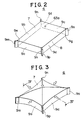
- Fig. 2 is a perspective view of a partition wall defining a fuel storing chamber therein, illustrating a basic shape of the partition wall;
- Fig. 3 is a perspective view of the partition wall, illustrating a state that the fuel storing chamber is filled with fuel;
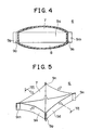
- Fig. 4 is a sectional view taken on line IV-IV in Fig. 3;
- Fig. 5 is a perspective view of the partition wall, illustrating a state that the amount of fuel in the fuel storing chamber has decreased;
- Fig. 6 is a sectional view taken on line VI-VI in Fig. 5;
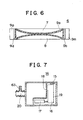
- Fig. 7 is a plan sectional view of an auxiliary fuel tank;
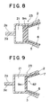
- Fig. 8 is an enlarged sectional view of a peripheral portion of the fuel tank corresponding to a corner portion of the partition wall;
- Fig. 9 is an enlarged sectional view a peripheral portion of the fuel tank corresponding to a portion of the partition wall other than the corner portions thereof;
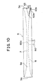
- Fig. 10 is a partially cutaway elevational view of the partition wall, a portion of residual fuel discharging pipe and a portion of the fuel pipe in the fuel tank of the first embodiment, illustrating a state that the amount of fuel in the fuel storing chamber is small;
- Fig. 11 is a partially cutaway elevational view of the partition wall, a portion of residual fuel discharging pipe and a portion of the fuel pipe in the fuel tank of a second embodiment, illustrating a state that the amount of fuel in the fuel storing chamber is small;
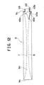
- Fig. 12 is a partially cutaway elevational view of the partition wall, a portion of residual fuel discharging pipe and a portion of the fuel pipe in the fuel tank of a third embodiment, illustrating a state that the amount of fuel in the fuel storing chamber is small;
- Fig. 13 a partially cutaway elevational view of the partition wall and a portion of the fuel pipe in the fuel tank of a fourth embodiment, illustrating a state that the amount of fuel in the fuel storing chamber is small; and
- Fig. 14 is a partially cutaway elevational view of the partition wall, a portion of residual fuel discharging pipe and a portion of the fuel pipe in the fuel tank of a fifth embodiment, illustrating a state that the amount of fuel in the fuel storing chamber is small.
-
- Preferred embodiments of the fuel tank of the present invention will be described in detail hereinafter with reference to the accompanying drawings. Like elements are represented by like numerals in the drawings, and description of like elements will not be repeated.
- The fuel tank of the invention is used as, for example, a tank for storing fuel to be supplied to an internal combustion engine. The fuel tank of the invention may also be used as a tank for simply storing fuel.
- Fig. 1 is a partially sectional view of a fuel tank according to a first embodiment of the invention. A fuel tank 1 has a housing (also termed as tank shell) 4 that forms an exterior of the fuel tank 1. The housing 4 is formed from a material having rigidity, such as a metal, a synthetic resin or the like. The housing 4 is made up of an
upper portion 2 and alower portion 3. Theupper portion 2 has an upwardly curved shape, and thelower portion 3 has a downwardly curved shape. Theupper portion 2 and thelower portion 3 are tightly joined atflanges portions - A partition wall 6 (see Fig. 2) having a generally hexahedral shape is disposed in an internal space defined by the
upper portion 2 and thelower portion 3 of the housing 4. Due to provision of thepartition wall 6, the internal space of the housing 4 is divided into an upper space 61a above thepartition wall 6, alower space 61b below thepartition wall 6, and afuel storing chamber 5 defined inside thepartition wall 6. - The
partition wall 6 defining therein thefuel storing chamber 5 has, as a basic shape, a generally rectangular parallelepipedal shape as shown in Fig. 2. Thepartition wall 6 has anupper wall 7 and alower wall 8 that have a generally rectangular shape and face each other in vertical directions, and four side walls (peripheral walls) 9a-9d interconnecting the corresponding sides of the upper andlower walls side walls 9a-9d is connected at its opposite ends to the adjacent side walls.Joint portions 9e-9h are formed between theside walls 9a-9d. Thejoint portions 9e-9h (corner portions of the rectangular parallelepipedal partition wall 6). A thinplaty jaw portion 9m-9p is protruded outward from eachjoint portion 9e-9h. Thejaw portions 9m-9p are formed integrally with the respectivejoint portions 9e-9h. Thejaw portions 9m-9p are provided for supporting thepartition wall 6 to the housing 4. - The
partition wall 6, having the upper andlower walls side walls 9a-9d and thejaw portions 9m-9p, is formed from a laminate structure sheet that is produced by, for example, coating both surfaces of a flat core portion of a copolymer resin of ethylene and vinyl, or nylon, with skin portions of a high-density polyethylene. Thepartition wall 6 substantially has rigidity, and it is deformable. - The area of the
upper wall 7 or thelower wall 8 is larger than the area of a side wall. The rigidity of theupper wall 7 and thelower wall 8 is less than that of theside walls 9a-9d. Thejaw portions 9m-9p have a greater rigidity than thewalls - As described above, the
partition wall 6 defines therein thefuel storing chamber 5, which assumes a generally rectangular parallelepipedal shape when thepartition wall 6 retains its basic shape. If fuel is supplied into thefuel storing chamber 5 so that the amount of fuel in thefuel storing chamber 5 exceeds an amount of fuel that can be stored into thefuel storing chamber 5 while the generally rectangular parallelepipedal shape of thefuel storing chamber 5 is retained (hereinafter, referred to as "predetermined amount"), theupper wall 7 and thelower wall 8 curve or expand outwards in such a manner as to separate apart from each other, and theside walls 9a-9d curve or sink inwards in such a manner as to come closer to one another, as shown in Figs. 3 and 4. - That is, if the amount of fuel in the
fuel storing chamber 5 exceeds the predetermined amount, theupper wall 7 arches or curves upwards and thelower wall 8 curves downwards, and theside walls 9a-9d curve horizontally inwards. In this manner, the amount of fuel storable in thefuel storing chamber 5, that is, the capacity of thefuel storing chamber 5, gradually increases. - Conversely, if fuel is discharged out of the
fuel storing chamber 5 so that the amount of fuel remaining in thefuel storing chamber 5 becomes less than the predetermined amount, the upper andlower walls side walls 9a-9d curve or dent inwards in such a manner as to come closer to each other, as shown in Figs. 5 and 6. - That is, if the amount of fuel in the
fuel storing chamber 5 becomes less than the predetermined amount, theupper wall 7 curves downwards and thelower wall 8 curves upwards, and theside walls 9a-9d curve horizontally inwards. In this manner, the amount of fuel storable in thefuel storing chamber 5 gradually decreases. - The amount of deformation of each of the
upper wall 7 and thelower wall 8 is greater than the amount of deformation of each of theside walls 9a-9d. The amount of deformation of each of thejaw portions 9m-9p is less than the amount of deformation of each of theside walls 9a-9d. Therefore, theupper wall 7 and thelower wall 8 may be considered as great-deformation faces, and theside walls 9a-9d may be considered as small-deformation faces, and thejaw portions 9m-9p may be considered as very small-deformation faces. - Referring back to Fig. 1, a fuel pipe (fuel passage) 60 for supplying fuel to or discharging fuel from the
fuel storing chamber 5 is connected to a substantially central portion of thelower wall 8 of thepartition wall 6. Thefuel pipe 60 branches into afuel supplying pipe 10 and afuel introducing pipe 20 that is connected to anauxiliary fuel tank 14 described below. - Fuel introduced via a fuel introducing opening (not shown) is supplied into the
fuel storing chamber 5 via thefuel supplying pipe 10 and thefuel pipe 60, and is also supplied into theauxiliary fuel tank 14 via thefuel introducing pipe 20. At the time of fuel discharge, fuel is drawn from thefuel storing chamber 5 into theauxiliary fuel tank 14 via thefuel pipe 60 and thefuel introducing pipe 20. - Junction portions of the
fuel supplying pipe 10 and thefuel introducing pipe 20 connecting to thefuel pipe 60 have bellows pipe walls and are expandable and bendable. The junction portions therefore allow curving deformation of thelower wall 8. In this embodiment, the entire length of thefuel introducing pipe 20 is formed by a bellows pipe. - The diameter of the
fuel pipe 60 is determined by the amount of fuel to be introduced into thefuel storing chamber 5, and it is normally about 25 mm to about 35 mm. It is normally difficult to connect thefuel pipe 60 to any one of theside walls 9a-9d because the height of theside walls 9a-9d is small. In order to facilitate connection of thefuel pipe 60 to one of theside walls 9a-9d, it may be considered that the connecting mouth of thefuel pipe 60 to aside wall 9a-9d is formed into a rectangular shape (elongated horizontally). However, if thefuel pipe 60 is connected to one of theside walls 9a-9d in this manner, the connecting mouth of thefuel pipe 60 will take up a considerably large area in the relatively small area of theside wall 9a-9d, so that thefuel pipe 60 will impede deformation (displacement) of the connected side wall. Thus, there will be a danger of insufficient deformation of theupper wall 7 and thelower wall 8. Therefore, connecting thefuel pipe 60 to theupper wall 7 or thelower wall 8 is considered more favorable. Theupper wall 7 and thelower wall 8 have a relatively large area and, therefore, will not be adversely affected to a great extent by connection of thefuel pipe 60 thereto. However, if thefuel pipe 60 is connected to theupper wall 7, it will be difficult to discharge fuel from thefuel storing chamber 5 via thefuel supplying pipe 10. If thefuel pipe 60 is connected to a portion of thelower wall 8 other than a substantially central portion thereof, deformation of the entirelower wall 8 will become non-uniform. Consequently, in the embodiment, thefuel pipe 60 is connected to a substantially central portion of thelower wall 8 as described above. - A fuel
vapor discharging pipe 11 for discharging gas, particularly, fuel vapor, out of thefuel storing chamber 5 is connected to a substantially central portion of theupper wall 7 of thepartition wall 6, via ashutoff valve 12. The fuelvapor discharging pipe 11 has flexibility and allows curving deformation of theupper wall 7. Theshutoff valve 12 shuts the fuelvapor discharging pipe 11 when the surface of liquid fuel in thefuel storing chamber 5 reaches theshutoff valve 12. Theshutoff valve 12 thus prevents leakage of fuel out of thefuel storing chamber 5. - The fuel
vapor discharging pipe 11 is connected to an intake passage (not shown) of an internal combustion engine, via acheck valve 13, and a charcoal canister (not shown) for temporarily adsorbing fuel vapor. Fuel vapor is released from the charcoal canister into the intake passage in accordance with the operating condition of the internal combustion engine. - The
check valve 13 opens when the pressure in the fuelvapor discharging pipe 11 between thecheck valve 13 and theshutoff valve 12 exceeds a predetermined positive pressure. Thecheck valve 13 closes when the pressure becomes lower than the predetermined positive pressure. This operation of thecheck valve 13 prevents gas from entering thefuel storing chamber 5 after theshutoff valve 12 is shut. - The
auxiliary fuel tank 14 for temporarily storing fuel from thefuel storing chamber 5 is disposed on thelower portion 3 of the housing 4, more specifically, under a portion of thelower wall 8 that extends substantially between the opening of thefuel pipe 60 and theside wall 9c. Theauxiliary fuel tank 14 contains afuel pump 16 for pumping fuel from theauxiliary fuel tank 14 to fuel injection valves (not shown) of the internal combustion engine via afuel conveying pipe 15. Thefuel pump 16 draws in fuel via afilter 17 that filters out dust or the like from fuel, regulates the fuel pressure to a predetermined pressure, and pumps out fuel to the fuel injection valves. - A
divider wall 18 extends substantially vertically upward from alower wall 50 of theauxiliary fuel tank 14. As shown in Fig. 7, thedivider wall 18 partially defines anaccommodation chamber 19 for disposing thefuel pump 16 and thefilter 17. Theaccommodation chamber 19 prevents exhaustion of fuel from the vicinity of thefilter 17 when theauxiliary fuel tank 14 is inclined so that the surface of liquid fuel in theauxiliary fuel tank 14 tilts. - As shown in Fig. 1, a lower surface of the
upper portion 2 of the housing 4 conforms to a shape of theupper wall 7 of thepartition wall 6 assumed when theupper wall 7 curves upwards. Similarly, an upper surface of anupper wall 52 of theauxiliary fuel tank 14 and an upper surface of a portion of thelower portion 3 of the housing 4, the portion being located under a portion of thelower wall 8 extending substantially between thefuel pipe 60 and theside wall 9a (hereinafter, the portion of thelower portion 3 will be referred to simply as "predetermined portion of thelower portion 3") conform to a shape of thelower wall 8 of thepartition wall 6 assumed when thelower wall 8 curves downwards. - Therefore, when the
lower wall 8 of thepartition wall 6 curves downwards and contacts the upper surface of theupper wall 52 of theauxiliary fuel tank 14 and the upper surface of the predetermined portion of thelower portion 3 of the housing 4, theupper wall 52 of theauxiliary fuel tank 14 and the predetermined portion of thelower portion 3 substantially prevent further downward deformation of thelower wall 8 of thepartition wall 6. Similarly, when theupper wall 7 of thepartition wall 6 curves upwards and contacts the lower surface of theupper portion 2 of the housing 4, theupper portion 2 substantially prevents further upward deformation of theupper wall 7 of thepartition wall 6. - That is, the
lower wall 8 and theupper wall 7 of thepartition wall 6 are prevented from excessively curving beyond a predetermined allowance of deformation by theupper wall 52 of theauxiliary fuel tank 14, the predetermined portion of thelower portion 3 of the housing 4, and theupper portion 2 of the housing 4. Theupper wall 7 and thelower wall 8 are thereby protected from damage and breakage. Furthermore, since theupper wall 52 of theauxiliary fuel tank 14 is utilized to prevent excessive deformation of thelower wall 8, a dead space below thepartition wall 6 can be substantially eliminated and the fuel tank 1 can be correspondingly reduced in size. - This embodiment is designed so that fuel supply into the
fuel storing chamber 5 via thefuel supplying pipe 10 is stopped when thelower wall 8 of thepartition wall 6 contacts the upper surface of theupper wall 52 of theauxiliary fuel tank 14 and the upper surface the predetermined portion of thelower portion 3 of the housing 4, and theupper wall 7 of thepartition wall 6 contacts the lower surface of theupper portion 2 of the housing 4. That is, theupper wall 52 of theauxiliary fuel tank 14, the predetermined portion of thelower portion 3 of the housing 4 and theupper portion 2 of the housing 4 determine a maximum fuel storing capacity of thefuel storing chamber 5. - Since fuel supply into the
fuel storing chamber 5 is stopped when the amount of fuel in thefuel storing chamber 5 reaches the maximum capacity of thefuel storing chamber 5, a problem will occur if the embodiment adopts a construction in which thefuel introducing pipe 20 is connected to one of theupper wall 7, thelower wall 8 and theside walls 9a-9d so that fuel is supplied from thefuel supplying pipe 10 into theauxiliary fuel tank 14 via thefuel storing chamber 5 and thefuel introducing pipe 20 and, at the time of fuel discharge, fuel is discharged from thefuel storing chamber 5 into theauxiliary fuel tank 14 via thefuel introducing pipe 20 connected to thefuel storing chamber 5. The problem is that theauxiliary fuel tank 14 will not be filled yet when the maximum capacity of thefuel storing chamber 5 is reached and fuel supply is stopped. - However, the embodiment adopts a construction in which the
fuel introducing pipe 20 branches from thefuel supplying pipe 10, so that fuel is substantially directly supplied from thefuel supplying pipe 10 into theauxiliary fuel tank 14 via thefuel introducing pipe 20, as described above. Therefore, it is ensured that theauxiliary fuel tank 14 will be filled with fuel before the maximum fuel storing capacity of thefuel storing chamber 5 is reached. - As can be seen in Figs. 1, 8 and 9, a
gap 21 having substantially the same height as theside walls 9a-9d of thepartition wall 6 is defined by theside walls 9a-9d and theupper portion 2 and thelower portion 3 of the housing 4. Thegap 21 extends along an inner surface of the entire joint peripheral portions of theupper portion 2 and thelower portion 3 of the housing 4. Thegap 21 houses thejaw portions 9m-9p of the partition wall 6 (see Fig. 8), and also houses theside walls 9a-9d and the connecting portions of the upper andlower walls side walls 9a-9d (see Fig. 9). Hereinafter, the connecting portions of the upper andlower walls side walls 9a-9d will be considered as extended portions of theside walls 9a-9d, and the connecting portions of the upper andlower walls side walls 9a-9d will be collectively referred to as "side wall-equivalent portion 62"). - The
upper portion 2 and thelower portion 3 of the housing 4 thus sandwich thejaw portions 9m-9p and the side wall-equivalent portion 62 of thepartition wall 6, and therefore support thepartition wall 6 so that thepartition wall 6 can slide in horizontal directions relative to the housing 4. That is, the joint peripheral portions of theupper portion 2 and thelower portion 3 of the housing 4 form aclamp portion 23 that clamps thejaw portions 9m-9p and the side wall-equivalent portion 62 of thepartition wall 6 slidably in horizontal directions (see Figs. 8 and 9). - The
jaw portions 9m-9p and the side wall-equivalent portion 62 slide horizontally relative to theclamp portion 23 when theupper wall 7 and thelower wall 8 undergo curving deformation. At the time of curving deformation of the upper andlower walls lower walls side walls 9a-9d is very small, and the displacement of portions of the connecting portions adjacent to thejaw portions 9m-9p is still smaller. Therefore, theclamp portion 23 does not considerably hinder the upper andlower walls - Since the
partition wall 6 is supported at thejaw portions 9m-9p and the side wall-equivalent portion 62 by the housing 4, thepartition wall 6 is allowed to undergo upward and downward deformation in accordance with the amount of fuel stored in thefuel storing chamber 5. Thepartition wall 6 may also be supported only at thejaw portions 9m-9p by the housing 4. - As shown in Fig. 2, an
opening 63a is formed in the side wall 9 of thepartition wall 6, at a position near thejoint portion 9f (a corner portion of the partition wall 6) and near the lower end of theside wall 9c, in this embodiment. As shown in Figs. 1 and 10, a residual fuel discharging pipe (residual fuel discharging passage) 63 is connected to theopening 63a. - The residual
fuel discharging pipe 63 has a smaller diameter than thefuel pipe 60. The residualfuel discharging pipe 63 is welded to theside wall 9c of thepartition wall 6, or formed together with thepartition wall 6. The residualfuel discharging pipe 63 is connected to the bellows fuel introducing pipe 20 (see Figs. 1 and 7). The residualfuel discharging pipe 63 may be connected to any one of theside walls 9a-9d. - As shown in Fig. 10, the residual
fuel discharging pipe 63 is connected to theside wall 9c in such a manner that a lowerside edge portion 63b of theopening 63a of the residualfuel discharging pipe 63 in theside wall 9c is lower than anopening 60a of thefuel pipe 60 formed in thelower wall 8 of thepartition wall 6, when a maximum upward deformation of thelower wall 8 is reached (also before the maximum upward deformation is reached). - In the fuel tank 1 constructed as described above, when fuel is supplied into the
partition wall 6 having a generally rectangular parallelepipedal basic shape as shown in Fig. 2 via thefuel supplying pipe 10 so that the amount of fuel in thefuel storing chamber 5 exceeds the aforementioned predetermined amount, theupper wall 7 and thelower wall 8 curve upwards and downwards, respectively, and theside walls 9a-9d curve inwards, as shown in Fig. 3. The curvature of the walls gradually increases with increases in the amount of fuel stored in thefuel storing chamber 5, until the maximum amount of fuel is stored in thefuel storing chamber 5. At this moment, theauxiliary fuel tank 14 has been filled with fuel. - Therefore, the fuel tank 1 of this embodiment enables storage of more fuel in the
fuel storing chamber 5 of thepartition wall 6 than a fuel tank in which anupper wall 7 and alower wall 8 do not curve upwards and downwards, respectively, with increases in the amount of fuel stored. - At the time of fuel discharge, the
fuel pump 16 is operated to pump out fuel from thefuel storing chamber 5 to the fuel injection valves of the internal combustion engine via thefuel pipe 60, thefuel introducing pipe 20, thefilter 17, and thefuel conveying pipe 15. As the amount of fuel in thefuel storing chamber 5 decreases, the upward curvature of theupper wall 7, the downward curvature of thelower wall 8 and the inward curvatures of theside walls 9a-9d gradually reduce. Thepartition wall 6 resumes the generally rectangular parallelepiped shape as shown in Fig. 2 when the amount of fuel in thefuel storing chamber 5 decreases to the aforementioned predetermined amount. - When fuel is further pumped out of the
fuel storing chamber 5 so that the amount of fuel in thefuel storing chamber 5 becomes less than the predetermined amount, theupper wall 7 and thelower wall 8 curve downwards and upwards, respectively, and theside walls 9a-9d curve inwards, as shown in Fig. 5, due to negative pressure caused by suction or pumping. The curvatures of these walls gradually increase with decreases in the amount of fuel in thefuel storing chamber 5. The progress of curving deformation of the walls is restrained when theupper wall 7 and thelower wall 8 closely contact at their substantially central portions as shown in Fig. 6. At this moment, thefuel storing chamber 5 has a shrunken shape as shown in Fig. 6, and it is filled with fuel without any gaseous space left therein. - Therefore, in comparison with a fuel tank in which neither an
upper wall 7 nor alower wall 8 curves with decreases in the amount of fuel stored, the fuel tank 1 of the embodiment reduces the gaseous space volume in thefuel storing chamber 5 by an amount corresponding to the capacity reduction of thefuel storing chamber 5 caused by the curvatures of the walls of thefuel storing chamber 5. - If fuel is further drawn from the
fuel storing chamber 5 by thefuel pump 16 after theupper wall 7 and thelower wall 8 closely contact at their substantially central portions due to a decrease in the amount of fuel in thefuel storing chamber 5, an amount of fuel present near a peripheral end portion of theupper wall 7 is discharged via theopening 60a of thefuel pipe 60. In this state, however, because theupper wall 7 and thelower wall 8 do not further deform, and because theopening 60a of thefuel pipe 60 is located at the uppermost position due to the upward curvature of thelower wall 8, a certain amount of fuel cannot be discharged via theopening 60a, but remains around theopening 60a, more specifically, near a peripheral end portion of thelower wall 8 of thefuel storing chamber 5. - However, in this embodiment, the residual
fuel discharging pipe 63 is connected to theside wall 9c at such a position that the lowerside edge portion 63b of theopening 63a of thepipe 63 in theside wall 9c becomes lower than theopening 60a of thefuel pipe 60 formed in thelower wall 8, at the time of the maximum upward curvature of thelower wall 8, as described above. Therefore, an amount of fuel remaining in thefuel storing chamber 5 after the maximum upward curvature of thelower wall 8 is discharged into theauxiliary fuel tank 14 via the residualfuel discharging pipe 63, and then pumped out to the fuel injection valves of the internal combustion engine. - In the embodiment, an amount of fuel that cannot be discharged via the
fuel pipe 60 but remains near the peripheral end portion of thelower wall 8 of thefuel storing chamber 5 due to the wall curvature can be discharged via the residualfuel discharging pipe 63. Therefore, the residual fuel amount of thefuel storing chamber 5 is minimized. Hence, a predetermined effective fuel capacity of thefuel storing chamber 5 is secured. Furthermore, since thefuel storing chamber 5 is provided with the plurality of fuel discharging passages, that is, thefuel pipe 60 and the residualfuel discharging pipe 63, fuel discharge from thefuel storing chamber 5 is not easily affected by the posture of the vehicle or the like. - In the preferred embodiment, the residual
fuel discharging pipe 63 is connected to a portion of a side wall of thepartition wall 6, the portion being near a corner portion of thepartition wall 6, because the portion of the side wall undergoes least deformation. However, this connecting position of the residualfuel discharging pipe 63 is not restrictive. For example, the residualfuel discharging pipe 63 may also be connected to a central portion of a side wall in the direction of the length of the side wall. - Fig. 11 is a partially cutaway elevational view of a partition wall of a fuel tank according to a second embodiment, wherein a portion of a residual fuel discharging pipe and a portion of a fuel pipe are also shown.
- The fuel tank of the second embodiment differs from that of the first embodiment in that a residual
fuel discharging pipe 64 is connected to alower wall 8 of thepartition wall 6 in the second embodiment, instead of the residualfuel discharging pipe 63 connected to theside wall 9c in the first embodiment. - The residual
fuel discharging pipe 64 is connected to thelower wall 8, at a position adjacent to a corner portion of thepartition wall 6, so that at the time of the maximum upward curvature of thelower wall 8, a lowerside edge portion 64b of an opening 64a of the residualfuel discharging pipe 64 in thelower wall 8 is lower than theopening 60a of thefuel pipe 60 formed in thelower wall 8. - This pipe connection also ensures that an amount of fuel that cannot be discharged via the
fuel pipe 60 but remains near a peripheral end portion of thelower wall 8 of thefuel storing chamber 5 due to an upward curvature of thelower wall 8 will be discharged via the residualfuel discharging pipe 64, thereby achieving substantially the same advantages as achieved by the first embodiment. - Although in this preferred embodiment, the residual
fuel discharging pipe 64 is connected to a least-deforming portion of thelower wall 8 near a corner portion of thepartition wall 6, this connecting position is not restrictive. - Fig. 12 is a partially cutaway elevational view of a partition wall of a fuel tank of a third embodiment, wherein a portion of a residual fuel discharging pipe and a portion of a fuel pipe are also shown.
- The fuel tank of the third embodiment differs from that of the first embodiment in that a
fuel pipe 65 is connected to a side wall of the partition wall 6 (e.g., aside wall 9c in Fig. 12) in the third embodiment, instead of thefuel pipe 60 connected to thelower wall 8 in the first embodiment. In the third embodiment, a residualfuel discharging pipe 63 is connected to a side wall (e.g., theside wall 9c in Fig. 12) as in the first embodiment. - In the third embodiment, the residual
fuel discharging pipe 63 is connected to theside wall 9c at such a position that alower side edge 63b of anopening 63a of the residualfuel discharging pipe 63 in theside wall 9c is below a lowerside edge portion 65b of anopening 65a of thefuel pipe 65 in theside wall 9c and that, at the time of the maximum upward curvature of thelower wall 8, the lowerside edge portion 63b of theopening 63a of the residualfuel discharging pipe 63 becomes lower than an uppermost portion of thelower wall 8. - This pipe connection also ensures that an amount of fuel that cannot be discharged via the
fuel pipe 65 but remains near a peripheral end portion of thelower wall 8 of thefuel storing chamber 5 due to an upward curvature of thelower wall 8 will be discharged via the residualfuel discharging pipe 63, thereby achieving substantially the same advantages as achieved by the first embodiment. - Fig. 13 is a partially cutaway elevational view of a partition wall of a fuel tank of a fourth embodiment, wherein a portion of a fuel pipe is also shown.
- The fuel tank of the fourth embodiment differs from the fuel tank of the third embodiment in that the residual
fuel discharging pipe 63 connected to a side wall of thepartition wall 6 is eliminated. In the fourth embodiment, afuel pipe 65 is connected to a side wall (e.g., aside wall 9c in Fig. 13) as in the third embodiment. - In the fourth embodiment, the
fuel pipe 65 is connected to theside wall 9c at such a position that a lowerside edge portion 65b of anopening 65a of thefuel pipe 65 becomes lower than an uppermost portion of alower wall 8 at the time of the maximum upward curvature of thelower wall 8. - This construction also ensures that an amount of fuel remaining near a peripheral end portion of the
lower wall 8 of thefuel storing chamber 5 at the time of an upward curvature of thelower wall 8 will be discharged via thefuel pipe 65, thereby achieving substantially the same advantages as achieved by the first embodiment. Furthermore, since a residual fuel discharging pipe is omitted, the construction can be correspondingly simplified and, therefore, the production cost can be reduced. - Fig. 14 is an elevational view of a partition wall of a fuel tank of a fifth embodiment, wherein a portion of a residual fuel discharging pipe and a portion of a fuel pipe are also shown.
- The fuel tank of the fifth embodiment differs from the fuel tank of the first embodiment in that the fuel tank 1 as in the first embodiment is tilted from a horizontal posture in the vehicle. Considering the ease of understanding the illustration, Fig. 14 shows only the
partition wall 6 defining afuel storing chamber 5 therein, and a portion of the residualfuel discharging pipe 63 and a portion of thefuel pipe 60. An arrow UP in the drawing indicates an upward direction relative to the vehicle. - The fuel tank 1 is installed in the vehicle in such a tilted posture that an
opening 63a of the residualfuel discharging pipe 63 connected to a side wall (e.g., aside wall 9c in Fig. 14) is located adjacent to a lowermost portion of thepartition wall 6. - This embodiment also ensures that an amount of fuel remaining in the
fuel storing chamber 5 at the time of an upward curvature of thelower wall 8 will be discharged from the residualfuel discharging pipe 63 connected to a substantially lowermost portion of thepartition wall 6, that is, a portion of thepartition wall 6 that includes or is adjacent to the lowest point in thepartition wall 6, thereby achieving substantially the same advantages as achieved by the first embodiment. Furthermore, due to the tilted posture of the fuel tank, fuel resides in a lower portion of thefuel storing chamber 5, that is, fuel naturally resides near theopening 63a of the residualfuel discharging pipe 63, so that fuel can be efficiently discharged via the residual fuel discharging pipe 63 (a good fuel discharging characteristic is achieved). - The construction of the fifth embodiment may also be applied to the second embodiment, in which the residual
fuel discharging pipe 64 is connected to thelower wall 8. It is also possible to support thepartition wall 6 in a tilted posture to the housing 4 of the fuel tank 1 and install the fuel tank 1 in a vehicle in a horizontal posture relative to the vehicle. That is, a gist of the fifth embodiment is that the partition wall 6 (fuel storing chamber 5) assumes a tilted posture relative to a vehicle and the residualfuel discharging pipe partition wall 6 that includes or is adjacent to the lowest point in thepartition wall 6. - While the present invention has been described with reference to what are presently considered to be preferred embodiments thereof, it is to be understood that the invention is not limited to the disclosed embodiments or constructions. To the contrary, the invention is intended to cover various modifications and equivalent arrangements included within the spirit and scope of the invention. For example, although in the foregoing embodiments, the residual
fuel discharging pipe fuel introducing pipe 20, the residualfuel discharging pipe auxiliary fuel tank 14 via a bellows pipe or a flexible pipe. - Although in the foregoing embodiments, the
partition wall 6 defining thefuel storing chamber 5 therein has a generally rectangular parallelepipedal basic shape, the basic shape of thepartition wall 6 may also be other prismal shapes with the upper andlower walls partition wall 6 may be suitably selected in accordance with the shape of an installation space of thepartition wall 6. - Although in the first, second and fifth embodiments, the
fuel pipe 60 is connected to a substantially central portion of thelower wall 8, thefuel pipe 60 may be connected to any portion of thelower wall 8 as long as the residualfuel discharging pipe opening 60a of thefuel pipe 60 formed in thelower wall 8.
Claims (11)
- A fuel tank (1) comprising a partition (6) defining a fuel storing chamber (5), the partition (6) being deformable in accordance with an amount of fuel stored in a fuel storing chamber (5), and a fuel passage (60, 65) open to the fuel storing chamber (5) for supplying the fuel into or discharging the fuel from the fuel storing chamber (5),
characterized in that
the partition (6) defines in it said fuel storing chamber (5) and includes a deformable lower wall (8) which curves upward when the amount of fuel in the fuel storing chamber (5) is decreased. - A fuel tank according to claim 1,
characterized in that
a discharged portion of the fuel in the fuel storing chamber (5) is discharged from the fuel storing chamber (5) via the fuel passage (60), while a remaining portion of the fuel in the fuel storing chamber (5) is not discharged via the fuel passage (60) due to a curvature of the lower wall (8) but through a residual fuel discharging passage (63, 64) via which the remaining portion of the fuel in the fuel storing chamber (5) is discharged. - A fuel tank according to claim 2,
characterized in that
the residual fuel discharging passage (63) is connected to the fuel storing chamber (5) in such a manner that a lower side edge portion of an opening of the residual fuel discharging passage to the fuel storing chamber is lower than an opening of the fuel passage (60) to the fuel storing chamber when the lower wall (8) is curved. - A fuel tank according to claim 1 or 2,
characterized in that
the fuel storing chamber is defined by an upper wall (7) having a polygonal shape, and the lower wall (8) having a polygonal shape and facing the upper wall, and a peripheral wall (9a-9d) extending between the upper wall and the lower wall. - A fuel tank according to claim 4,
characterized in that
the residual fuel discharging passage (63) is connected to the peripheral wall (9c) in such a manner that a lower side edge portion of an opening of the residual fuel discharging passage in the peripheral wall is lower than an opening of the fuel passage (60) formed in the lower wall at least when the lower wall (8) is curved to a maximum extent. - A fuel tank according to claim 4,
characterized in that
the fuel passage (60) is connected to the lower wall (8), and
the residual fuel discharging passage (64) is connected to the lower wall (8) in such a manner that at least when the lower wall (8) is curved to a maximum extent, a lower side edge portion of an opening of the residual fuel discharging passage in the lower wall (8) is lower than an opening of the fuel passage (60) formed in the lower wall (8). - A fuel tank according to claim 4,
characterized in that
the fuel passage (65) is connected to the peripheral wall (9c), and the residual fuel discharging passage (63) is connected to the peripheral wall (9c) in such a manner that at least when the lower wall (8) is curved to a maximum extent, a lower side edge portion of an opening of the residual fuel discharging passage (63) in the peripheral wall (9c) is lower than an uppermost portion of the lower wall (8) and than a lower side edge portion of an opening of the fuel passage (65) in the peripheral wall (9c). - A fuel tank according to claim 2,
characterized in that
the residual fuel discharging passage (63) discharges into the fuel passage (60) the amount of the fuel that remains without being discharged via the fuel passage (60). - A fuel tank according to claim 2,
characterized by
an auxiliary fuel tank (14) that temporarily stores the fuel, the residual fuel discharging passage (63) discharging into the auxiliary fuel tank (14) the amount of the fuel that remains without being discharged via the fuel passage (60). - A fuel tank according to claim 1,
characterized in that
the fuel storing chamber is defined by an upper wall (7) having a polygonal shape, and the lower wall (8) having a polygonal shape and facing the upper wall, and a peripheral wall (9a-9d) extending between the upper wall and the lower wall, wherein a lower side edge portion of an opening of the fuel passage (65) in the peripheral wall (9c) is lower than an uppermost portion of the lower wall (8). - A vehicle comprising a fuel tank according to any one of claims 2 to 9,
characterized in that
the fuel storing chamber (5) is tilted relative to a horizontal direction, and the residual fuel discharging passage (63) is connected to a substantially lowermost portion of the fuel storing chamber (5).
Applications Claiming Priority (2)
| Application Number | Priority Date | Filing Date | Title |
|---|---|---|---|
| JP23580798 | 1998-08-21 | ||
| JP23580798A JP3361459B2 (en) | 1998-08-21 | 1998-08-21 | Fuel tank and vehicle equipped with this |
Publications (3)
| Publication Number | Publication Date |
|---|---|
| EP0982169A2 EP0982169A2 (en) | 2000-03-01 |
| EP0982169A3 EP0982169A3 (en) | 2000-11-08 |
| EP0982169B1 true EP0982169B1 (en) | 2003-11-26 |
Family
ID=16991551
Family Applications (1)
| Application Number | Title | Priority Date | Filing Date |
|---|---|---|---|
| EP99115225A Expired - Lifetime EP0982169B1 (en) | 1998-08-21 | 1999-08-02 | Fuel tank and vehicle equipped with the same |
Country Status (4)
| Country | Link |
|---|---|
| US (1) | US6439417B1 (en) |
| EP (1) | EP0982169B1 (en) |
| JP (1) | JP3361459B2 (en) |
| DE (1) | DE69913054T2 (en) |
Families Citing this family (5)
| Publication number | Priority date | Publication date | Assignee | Title |
|---|---|---|---|---|
| DE10023066B4 (en) * | 2000-05-11 | 2009-01-22 | Volkswagen Ag | Storage container system for a motor vehicle |
| US20050242109A1 (en) * | 2004-04-30 | 2005-11-03 | Avon Rubber & Plastics, Inc. | Liquid storage and dispensing system and method |
| DE102009007022A1 (en) * | 2009-01-31 | 2010-08-05 | Daimler Ag | Liquid tank i.e. fuel container, for commercial vehicle, has varying unit liquid and/or gas-tight attached to inner contour of container wall in region of empty space and varying variable volume of surge absorption device |
| JP2020016158A (en) * | 2018-07-23 | 2020-01-30 | 京三電機株式会社 | Fuel supply device |
| JP2020026761A (en) * | 2018-08-10 | 2020-02-20 | 株式会社やまびこ | Fuel containers and work machines |
Family Cites Families (11)
| Publication number | Priority date | Publication date | Assignee | Title |
|---|---|---|---|---|
| US2758747A (en) * | 1949-12-10 | 1956-08-14 | Standard Oil Co | Multiple compartment tank |
| US2724418A (en) * | 1953-03-02 | 1955-11-22 | Goodrich Co B F | Fluid-receiving container with volumeresponsive pressure-relief and overflow valve assembly |
| BE542014A (en) * | 1954-10-18 | |||
| US3648886A (en) * | 1970-05-11 | 1972-03-14 | William L Pringle | Fuel tank assembly |
| US3747800A (en) * | 1971-02-16 | 1973-07-24 | C Viland | Preventing air pollution and improving safety of automobile and similar tanks |
| US4008831A (en) * | 1972-11-20 | 1977-02-22 | Jacques Vidilles | Safety reservoir for hydrocarbons and dangerous liquids |
| DE2658720C3 (en) * | 1976-12-24 | 1982-01-28 | Deutsche Forschungs- und Versuchsanstalt für Luft- und Raumfahrt e.V., 5300 Bonn | Latent heat storage for holding a heat-storing medium |
| US5596971A (en) * | 1994-10-21 | 1997-01-28 | Toyota Jidosha Kabushiki Kaisha | Fuel storing device for motor vehicle |
| JP3518087B2 (en) | 1994-10-21 | 2004-04-12 | トヨタ自動車株式会社 | Vehicle fuel storage device |
| JP3178991B2 (en) | 1995-06-23 | 2001-06-25 | 矢崎総業株式会社 | Liquid tank |
| JP3385880B2 (en) * | 1995-11-20 | 2003-03-10 | トヨタ自動車株式会社 | Automotive fuel storage device |
-
1998
- 1998-08-21 JP JP23580798A patent/JP3361459B2/en not_active Expired - Fee Related
-
1999
- 1999-08-02 DE DE69913054T patent/DE69913054T2/en not_active Expired - Lifetime
- 1999-08-02 EP EP99115225A patent/EP0982169B1/en not_active Expired - Lifetime
- 1999-08-04 US US09/369,036 patent/US6439417B1/en not_active Expired - Lifetime
Also Published As
| Publication number | Publication date |
|---|---|
| EP0982169A2 (en) | 2000-03-01 |
| US6439417B1 (en) | 2002-08-27 |
| EP0982169A3 (en) | 2000-11-08 |
| DE69913054D1 (en) | 2004-01-08 |
| JP2000062476A (en) | 2000-02-29 |
| JP3361459B2 (en) | 2003-01-07 |
| DE69913054T2 (en) | 2004-06-03 |
Similar Documents
| Publication | Publication Date | Title |
|---|---|---|
| EP0945298B1 (en) | Fuel tank | |
| US6472635B2 (en) | Fuel tank filler assembly for engine driven welder | |
| US5722374A (en) | Fuel storing device for an automobile | |
| JP6287967B2 (en) | Fuel tank structure | |
| US5979417A (en) | Fuel reserving device | |
| US5975331A (en) | Fuel tank comprising a separator film | |
| US6439417B1 (en) | Fuel tank and vehicle equipped with the same | |
| KR100372627B1 (en) | Fuel Reservoir | |
| JP3362540B2 (en) | Vehicle fuel storage device | |
| KR100310889B1 (en) | A fuel tank | |
| JP3389601B2 (en) | Fuel tank | |
| JP2004060530A (en) | Canister body mounting structure | |
| JP2000062477A (en) | Fuel tank | |
| JP3395553B2 (en) | Vehicle fuel tank | |
| JP6646940B2 (en) | Vehicle fuel tank | |
| US20230249542A1 (en) | Portable Fuel Tank Assembly and Portable Fuel Tank Support | |
| US7509949B2 (en) | Vaporized fuel processing device and vehicle with the same | |
| JP2000118249A (en) | Fuel tank | |
| JP4299831B2 (en) | Fuel tank | |
| JPH11278066A (en) | Fuel tank | |
| JP3334533B2 (en) | Fuel tank | |
| JP6527360B2 (en) | Vehicle fuel tank | |
| US20260028952A1 (en) | Vapor separator tank | |
| JPH11278068A (en) | Fuel tank | |
| JP2010174684A (en) | Ship propeller |
Legal Events
| Date | Code | Title | Description |
|---|---|---|---|
| PUAI | Public reference made under article 153(3) epc to a published international application that has entered the european phase |
Free format text: ORIGINAL CODE: 0009012 |
|
| 17P | Request for examination filed |
Effective date: 19990802 |
|
| AK | Designated contracting states |
Kind code of ref document: A2 Designated state(s): DE FR GB |
|
| AX | Request for extension of the european patent |
Free format text: AL;LT;LV;MK;RO;SI |
|
| RAP1 | Party data changed (applicant data changed or rights of an application transferred) |
Owner name: HORIE KINZOKU KOGYO KABUSHIKI KAISHA Owner name: TOYOTA JIDOSHA KABUSHIKI KAISHA |
|
| RIN1 | Information on inventor provided before grant (corrected) |
Inventor name: ISHIKAWA, TAKUYA Inventor name: GOTO, TEIJIRO Inventor name: ISHIKAWA, TAKASHI Inventor name: ARASE, TOMOYASU |
|
| PUAL | Search report despatched |
Free format text: ORIGINAL CODE: 0009013 |
|
| AK | Designated contracting states |
Kind code of ref document: A3 Designated state(s): AT BE CH CY DE DK ES FI FR GB GR IE IT LI LU MC NL PT SE |
|
| AX | Request for extension of the european patent |
Free format text: AL;LT;LV;MK;RO;SI |
|
| AKX | Designation fees paid |
Free format text: DE FR GB |
|
| 17Q | First examination report despatched |
Effective date: 20020522 |
|
| GRAH | Despatch of communication of intention to grant a patent |
Free format text: ORIGINAL CODE: EPIDOS IGRA |
|
| GRAS | Grant fee paid |
Free format text: ORIGINAL CODE: EPIDOSNIGR3 |
|
| GRAA | (expected) grant |
Free format text: ORIGINAL CODE: 0009210 |
|
| AK | Designated contracting states |
Kind code of ref document: B1 Designated state(s): DE FR GB |
|
| REG | Reference to a national code |
Ref country code: GB Ref legal event code: FG4D |
|
| REF | Corresponds to: |
Ref document number: 69913054 Country of ref document: DE Date of ref document: 20040108 Kind code of ref document: P |
|
| ET | Fr: translation filed | ||
| RIN2 | Information on inventor provided after grant (corrected) |
Inventor name: ISHIKAWA, TAKUYA Inventor name: GOTO, TEIJIRO Inventor name: ISHIKAWA, TAKASHI Inventor name: ARASE, TOMOYASU |
|
| PLBE | No opposition filed within time limit |
Free format text: ORIGINAL CODE: 0009261 |
|
| STAA | Information on the status of an ep patent application or granted ep patent |
Free format text: STATUS: NO OPPOSITION FILED WITHIN TIME LIMIT |
|
| 26N | No opposition filed |
Effective date: 20040827 |
|
| REG | Reference to a national code |
Ref country code: FR Ref legal event code: PLFP Year of fee payment: 18 |
|
| REG | Reference to a national code |
Ref country code: FR Ref legal event code: PLFP Year of fee payment: 19 |
|
| REG | Reference to a national code |
Ref country code: FR Ref legal event code: PLFP Year of fee payment: 20 |
|
| PGFP | Annual fee paid to national office [announced via postgrant information from national office to epo] |
Ref country code: FR Payment date: 20180612 Year of fee payment: 20 |
|
| PGFP | Annual fee paid to national office [announced via postgrant information from national office to epo] |
Ref country code: DE Payment date: 20180717 Year of fee payment: 20 |
|
| PGFP | Annual fee paid to national office [announced via postgrant information from national office to epo] |
Ref country code: GB Payment date: 20180801 Year of fee payment: 20 |
|
| REG | Reference to a national code |
Ref country code: DE Ref legal event code: R071 Ref document number: 69913054 Country of ref document: DE |
|
| REG | Reference to a national code |
Ref country code: GB Ref legal event code: PE20 Expiry date: 20190801 |
|
| PG25 | Lapsed in a contracting state [announced via postgrant information from national office to epo] |
Ref country code: GB Free format text: LAPSE BECAUSE OF EXPIRATION OF PROTECTION Effective date: 20190801 |