EP0982118B1 - Machine for folding a sheet of cardboard - Google Patents
Machine for folding a sheet of cardboard Download PDFInfo
- Publication number
- EP0982118B1 EP0982118B1 EP99306914A EP99306914A EP0982118B1 EP 0982118 B1 EP0982118 B1 EP 0982118B1 EP 99306914 A EP99306914 A EP 99306914A EP 99306914 A EP99306914 A EP 99306914A EP 0982118 B1 EP0982118 B1 EP 0982118B1
- Authority
- EP
- European Patent Office
- Prior art keywords
- machine
- sheet
- folding
- cam
- progressively
- Prior art date
- Legal status (The legal status is an assumption and is not a legal conclusion. Google has not performed a legal analysis and makes no representation as to the accuracy of the status listed.)
- Expired - Lifetime
Links
Images



Classifications
-
- B—PERFORMING OPERATIONS; TRANSPORTING
- B31—MAKING ARTICLES OF PAPER, CARDBOARD OR MATERIAL WORKED IN A MANNER ANALOGOUS TO PAPER; WORKING PAPER, CARDBOARD OR MATERIAL WORKED IN A MANNER ANALOGOUS TO PAPER
- B31B—MAKING CONTAINERS OF PAPER, CARDBOARD OR MATERIAL WORKED IN A MANNER ANALOGOUS TO PAPER
- B31B50/00—Making rigid or semi-rigid containers, e.g. boxes or cartons
-
- B—PERFORMING OPERATIONS; TRANSPORTING
- B31—MAKING ARTICLES OF PAPER, CARDBOARD OR MATERIAL WORKED IN A MANNER ANALOGOUS TO PAPER; WORKING PAPER, CARDBOARD OR MATERIAL WORKED IN A MANNER ANALOGOUS TO PAPER
- B31B—MAKING CONTAINERS OF PAPER, CARDBOARD OR MATERIAL WORKED IN A MANNER ANALOGOUS TO PAPER
- B31B50/00—Making rigid or semi-rigid containers, e.g. boxes or cartons
- B31B50/26—Folding sheets, blanks or webs
- B31B50/36—Folding sheets, blanks or webs by continuously feeding the sheets, blanks or webs to stationary members, e.g. plates, ploughs or cores
-
- B—PERFORMING OPERATIONS; TRANSPORTING
- B31—MAKING ARTICLES OF PAPER, CARDBOARD OR MATERIAL WORKED IN A MANNER ANALOGOUS TO PAPER; WORKING PAPER, CARDBOARD OR MATERIAL WORKED IN A MANNER ANALOGOUS TO PAPER
- B31B—MAKING CONTAINERS OF PAPER, CARDBOARD OR MATERIAL WORKED IN A MANNER ANALOGOUS TO PAPER
- B31B2100/00—Rigid or semi-rigid containers made by folding single-piece sheets, blanks or webs
-
- B—PERFORMING OPERATIONS; TRANSPORTING
- B31—MAKING ARTICLES OF PAPER, CARDBOARD OR MATERIAL WORKED IN A MANNER ANALOGOUS TO PAPER; WORKING PAPER, CARDBOARD OR MATERIAL WORKED IN A MANNER ANALOGOUS TO PAPER
- B31B—MAKING CONTAINERS OF PAPER, CARDBOARD OR MATERIAL WORKED IN A MANNER ANALOGOUS TO PAPER
- B31B2100/00—Rigid or semi-rigid containers made by folding single-piece sheets, blanks or webs
- B31B2100/002—Rigid or semi-rigid containers made by folding single-piece sheets, blanks or webs characterised by the shape of the blank from which they are formed
- B31B2100/0022—Rigid or semi-rigid containers made by folding single-piece sheets, blanks or webs characterised by the shape of the blank from which they are formed made from tubular webs or blanks, including by tube or bottom forming operations
-
- B—PERFORMING OPERATIONS; TRANSPORTING
- B31—MAKING ARTICLES OF PAPER, CARDBOARD OR MATERIAL WORKED IN A MANNER ANALOGOUS TO PAPER; WORKING PAPER, CARDBOARD OR MATERIAL WORKED IN A MANNER ANALOGOUS TO PAPER
- B31B—MAKING CONTAINERS OF PAPER, CARDBOARD OR MATERIAL WORKED IN A MANNER ANALOGOUS TO PAPER
- B31B2120/00—Construction of rigid or semi-rigid containers
- B31B2120/30—Construction of rigid or semi-rigid containers collapsible; temporarily collapsed during manufacturing
-
- B—PERFORMING OPERATIONS; TRANSPORTING
- B31—MAKING ARTICLES OF PAPER, CARDBOARD OR MATERIAL WORKED IN A MANNER ANALOGOUS TO PAPER; WORKING PAPER, CARDBOARD OR MATERIAL WORKED IN A MANNER ANALOGOUS TO PAPER
- B31B—MAKING CONTAINERS OF PAPER, CARDBOARD OR MATERIAL WORKED IN A MANNER ANALOGOUS TO PAPER
- B31B50/00—Making rigid or semi-rigid containers, e.g. boxes or cartons
- B31B50/26—Folding sheets, blanks or webs
- B31B50/56—Folding sheets, blanks or webs by rotary members co-operating with blades
Definitions
- This invention relates to a machine for folding a sheet of cardboard according to the preamble of claim 1 and relates to a method executed by the machine according to claim 1.
- US-A-5 827 162 discloses a machine for folding paperboard blanks that has a number of helix folding assemblies.
- Each helix folding assembly comprises a shaft and a plurality of spokes extending therefrom.
- a rod is supported on the spokes and the arrangement is such that the rod forms a cylindrical helix of constant radius around the shaft.
- paperboard blanks are folded by the helix folding assembly.
- the disadvantage of such rod arrangements is mentioned above.
- the present invention provides a machine for folding a sheet of cardboard, which machine comprises:
- a method of folding sheet of cardboard which method comprises the steps of:
- a machine 10 comprises a pair of spaced-apart conveyors 12 having conveyor belts 14 which convey individual container blanks 16 to be folded in the direction of arrow A.
- Conveyor belts 14 are driven by motors M' and, as previously discussed, the container blanks 16 may be composed of any difficult to fold material.
- container blanks will be described comprising sheets of corrugated cardboard since these are particularly difficult to fold precisely and accurately along a predetermined fold line as previously described.
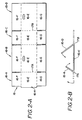
- FIGs. 2-A and 2-B illustrate a container blank 16 which includes four panels 16A-D.
- Each of panels 16A-D comprises a body portion 16E and a leading flap 16F and a trailing flap 16G.
- the container blank also includes a pre-glued tab 16H which will engage panel 16D and permanently connect panels 16A and 16D when panels 16A and 16D are folded along fold lines 17A, 17B and 17C.
- the folds along lines 17A and 17B must be extremely precise or the four panels will not be square and the eventually completed container may not accept the intended articles.
- a series of creasing rollers 20 These are shown in Figs. 1 and 3. These creasing rollers are aligned along the lines of the proposed fold; i.e., along fold lines 17A and B.
- the panels 16 A and 16 D are progressively engaged by a series of rotating folding cams 22.
- cams 22 Four of cams 22 are illustrated on the left side of the machine 10 in Fig. 1, and it will be understood that an additional four folding cams are located on the right side. It will also be understood that the folding cams 22 are driven through suitable gearing by motors M".
- each folding stage folds the respective panel by about 20 to 40 degrees, and preferably 25 to 35 degrees, and most preferably 30 degrees, then the panels are folded in the order of 80 to 160 degrees, and more preferably in the order of 100 to 140 degrees, and most preferably by about 120 degrees. It has been discovered that it is the very initial contact and very initial folding action which is most critical in successfully obtaining a precise and squared fold.
- the rotary folding cams 22 may be used to fold the panels by the complete 180 degrees required for the finished product, it is preferable to complete the fold in several stages so as to fold each panel in the order of only 80 to 140 degrees, and then utilize conventional rods or other means to complete the folding of each panel to be 180 degrees from its starting position such as to become parallel to the panel over which it is being folded.
- each of panels 16A and 16D is progressively folded upwardly and toward the center of the container blank 16 as shown in Fig. 2-B, or completely such that panels 16A and 16D are substantially parallel to panels 16 B and 16 C , respectively.
- creasing rollers 20 are schematically illustrated in Fig. 3 wherein numeral 12' represents the left one of the spaced-apart conveyor supports carrying conveyor belt 14.
- a low-friction guide 15 is positioned between the support and the conveyor belt 14.
- Conveyor belt 14 conveys the left hand side of the container blank 16 which includes side panel 16A.
- each of the creasing rollers 20 has a cylindrical body portion 20 a which engages the container blank 16 and holds the container blank 16 securely against the conveyor belt 14.
- each of the creasing rollers 20 also includes an annular rim portion 20 b which has a diameter larger than that of the body portion.
- the cross-sectional shape of the annular rim portion 20 b is generally an annular V-shape with the bottom of the "V" being blunt and smooth so as not to tear or otherwise damage the container blank 16.
- annular rim portion 20 b presses down into the blank and creases, or further creases the pre-creased blank precisely along the intended fold line before the container blank 16 reaches the first stage of folding, and also during the initial stage or stages of the folding action.
- roller body portion 20 a and rim portion 20 b may be mounted on separate shafts, and that these portions may be supported and positioned against the upper surfaces of the container blanks 16 by separate support mechanisms.
- rim portion 20 b with its annular V-shaped cross-section engaging the container blanks 16 which performs the creasing function, and that other means such as solid rollers, belts, rods, etc. may be utilized to perform the hold-down function of body portion 20 a .
- Fig. 4 is a top plan view of one spiral cam folder 22, and Figs. 5A to 5E show the cross-sections of the spiral cam folder 22 at five locations along the axial length thereof.
- the spiral cam folder 22 has an outer, solid surface of revolution 22 a which extends the full axial length of the folding cam, and it is this solid surface of revolution 22a which contacts the panels to be folded.
- the spiral cam folder 22 has a leading edge 22 b and a trailing edge 22 c neither of which contact leading flap 16 F or panel 16 A to be folded. Also, it will be noted from Figs. 5A-5E that all of the cross-sections of the spiral cam folder 22 are of spiral shapes of different radii.
- Figs. 6-14 illustrate the rotary positions of the spiral cam folder 22 in the first folding stage (Stage I) as the panel of one container blank 16 passes over the spiral cam folder 22.
- Figs. 6-9 illustrate four rotary positions of the spiral cam folder 22 as a container blank 16 approaches the elongated spiral cam folder 22 and passes over the small end portion thereof. In these approach positions, the panel is above that portion of the spiral cam folder 22 which is of constant radius and it will be noted that the spiral cam folder 22 is rotating in counter-clockwise direction shown by arrow B. As a result, the panel of the container blank 16 remains horizontal as shown since the folding action has not yet begun.
- the spiral cam folder 22 is shown as it is about to begin the folding action. In this position it will be noted that trailing edge 22 c has rotated below the level of the container blank 16; i.e., below the board line, so that the container blank 16 may continue to pass over the smaller diameter portions of the spiral cam folder 22. Also, it will be noted that the panel is being engaged by the last portion of the spiral surface having a constant radius, and the panel is about to be engaged by portions of the folding cam having a progressively greater radius. Thus, as shown in Figs. 11-13, outer solid surface 22 a of the spiral cam folder 22 continues to increase the folding action on the panel as the panel is engaged by the progressively larger diameter portions of the spiral cam folder 22.
- the angular portion of the spiral surface which is of progressively increasing diameter is preferably in the order of 130° to 145°.
- the panel is engaged by the solid surface portion 22 a which is of the maximum and constant diameter.
- This constant diameter portion of the spiral cam folder 22 holds the panel in its partially folded position, and sets the fold as illustrated in Figs. 13 and 14 as the container blank 16 continues to be moved forward by the conveyor belt 14 into the second stage (Stage II) of the machine 10.
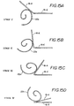
- spiral cam folder 22 in stages II, III and IV is the same as that previously described, except that, each succeeding stage increases the angle of the fold until the last stage completes the fold with the panels 16A and 16D lying in the order of 100 or more degrees from the initial horizontal position as illustrated in Figs. 15A-15D.
- the preferred embodiment includes motor controls which coordinate the position of each blank by timing the conveyor motor M' with the timing of motors M" which control the angular position of each spiral cam folder 22.
- each of the successive spiral cam folders 22 in Stages II-IV is positioned higher than the preceding stage, and each succeeding stage is also positioned closer to the center of the container blank 16.
- the panels of the container blanks 16 may be folded precisely and over an angle of 120 or more degrees from the horizontal position illustrated in Fig. 1.
- none of the spiral cam folders 22 ever contact the leading edge of the blank or any portion of leading flaps 16F of the blank. Rather, all contact with the panels of the blanks is made by the solid and continuous outer surface of revolution 22 a of the spiral cam folder 22.
- the direction of the force applied to the panels by surface 22 a is entirely perpendicular to the fold line and direction of travel of the container blank 16.
- the container blanks 16 are not skewed or bent by contact of their leading edges or leading flaps, and moreover, the force of the folding action is substantially uniformly distributed along the surface of the entire panel by the solid surface of revolution of the spiral cam folders 22.
- the container blanks 16 are folded acceptably even at the very high production speeds of the production machines which may precede the folding section.
Landscapes
- Making Paper Articles (AREA)
- Folding Of Thin Sheet-Like Materials, Special Discharging Devices, And Others (AREA)
Description
- This invention relates to a machine for folding a sheet of cardboard according to the preamble of claim 1 and relates to a method executed by the machine according to claim 1.
- It is well known that some sheet materials are extremely difficult to fold in a precise and uniform manner along a predetermined fold line because the nature of the material deforms irregularly as the material is being folded. This problem is particularly severe in the case of cardboard sheets, particularly corrugated cardboard sheets which tend to buckle at the fold line irregularly and cause the folded portion to become misaligned relative to the body portion of the sheet. In the case of container blanks which have panels to be folded in order to form a container, the accuracy of the fold and the precise alignment of the folded panels is absolutely critical to the formation of a successful product. That is, any deformation or misalignment of the panels changes the shape of the container and may make it unacceptable. When folded in precise alignment, a container blank is said to be "square" or "squared".
- This problem and the need to square each folded container blank is discussed, for example in U.S. Patent 2,986,078 which includes illustrations of squared and skewed containers.
- Many attempts have been made to solve this problem, but none have totally eliminated the problem, and current line speeds of up to 5m/s (1, 000 board feet per minute) of container blanks have made it even more difficult. All known prior attempts have utilized rods or belts to perform the folding action. These only make point or line contact with the flap of the panel, and the force is applied at an acute angle with respect to the fold line which is also the direction of travel of the blank. In addition, the initial contact of the rod or belt is with the leading edge of the flap. Both of these factors tend to bend the flap and/or twist it as the panel is being folded. Thus, there remains a critical need for a highspeed machine which can produce acceptably squared container blanks with a substantially lower product rejection rate.
- For example US-A-5 827 162 discloses a machine for folding paperboard blanks that has a number of helix folding assemblies. Each helix folding assembly comprises a shaft and a plurality of spokes extending therefrom. A rod is supported on the spokes and the arrangement is such that the rod forms a cylindrical helix of constant radius around the shaft. In use, paperboard blanks are folded by the helix folding assembly. The disadvantage of such rod arrangements is mentioned above.
- The present invention provides a machine for folding a sheet of cardboard, which machine comprises:
- (a) a conveyor for conveying said sheet through said machine in a first direction, and
- (b) folding means for engaging a first portion of said sheet and folding it relative to a second portion thereof, said folding means comprising a cam arranged to rotate about an axis substantially parallel to said first direction, characterised in that said cam has spiral cross-sections of progressively increasing radii in said first direction to, in use, progressively fold said sheet as it passes through said machine.
-
- Further features of the invention are set out in Claims 2 et seq.
- According to another aspect of the present invention there is provided a method of folding sheet of cardboard, which method comprises the steps of:
- (a) conveying said sheet in a first direction through a machine;
- (b) engaging a first portion of said sheet and
folding it relative to a second portion thereof with a
cam rotating about an axis substantially parallel to said
first direction,
characterised by the step of - (c) progressively folding said sheet as it moves in said first direction with a cam having spiral cross-sections of progressively increasing radii in said first direction.
-
- For a better understanding of the present invention reference will now be made, by way of example, to the accompanying drawings, in which:-
- Fig. 1 is a simplified perspective view of a machine in accordance with the present invention;
- Fig. 2-A is a top plan view of a typical container blank to be folded;
- Fig. 2-B is a schematic elevational view of the container blank showing the panels being folded;
- Fig. 3 is a simplified and schematic sectional view showing the cooperation of the spiral folding cam below the panel and one creasing roller above the container blank;
- Fig. 4 is a schematic top plan view of one spiral folding cam;
- Figs. 5A to 5E are sectional views taken along view lines A-E of Fig. 4;
- Figs. 6 to 14 are schematic sectional illustrations showing the rotary positions of the first stage of the spiral folding cam as it folds one panel of the container blank; and
- Figs. 15A to 15D are schematic illustrations showing the folding of one panel as the container blank passes through four stages of spiral folding cams.
-
- Referring to Fig. 1, a machine 10 comprises a pair of spaced-
apart conveyors 12 havingconveyor belts 14 which conveyindividual container blanks 16 to be folded in the direction of arrowA. Conveyor belts 14 are driven by motors M' and, as previously discussed, thecontainer blanks 16 may be composed of any difficult to fold material. However, for purposes of illustration of the structure and mode of operation of the present embodiment container blanks will be described comprising sheets of corrugated cardboard since these are particularly difficult to fold precisely and accurately along a predetermined fold line as previously described. - For purposes of clarifying the terminology used in the corrugated container industry, Figs. 2-A and 2-B illustrate a container blank 16 which includes four
panels 16A-D. Each ofpanels 16A-D comprises a body portion 16E and a leading flap 16F and a trailing flap 16G. Typically, the container blank also includes a pre-glued tab 16H which will engage panel 16D and permanently connectpanels 16A and 16D whenpanels 16A and 16D are folded alongfold lines lines - As the
container blanks 16 enter the machine 10, the upper surfaces of thecontainer blanks 16 are engaged by a series ofcreasing rollers 20. These are shown in Figs. 1 and 3. These creasing rollers are aligned along the lines of the proposed fold; i.e., alongfold lines 17A and B. As each of the blanks progresses into the folding machine, thepanels 16A and 16D are progressively engaged by a series of rotatingfolding cams 22. Four ofcams 22 are illustrated on the left side of the machine 10 in Fig. 1, and it will be understood that an additional four folding cams are located on the right side. It will also be understood that thefolding cams 22 are driven through suitable gearing by motors M". While more or less than four stages of folding may be employed, it has been discovered that four stages of folding may be preferred. For example, it has been discovered that if each folding stage folds the respective panel by about 20 to 40 degrees, and preferably 25 to 35 degrees, and most preferably 30 degrees, then the panels are folded in the order of 80 to 160 degrees, and more preferably in the order of 100 to 140 degrees, and most preferably by about 120 degrees. It has been discovered that it is the very initial contact and very initial folding action which is most critical in successfully obtaining a precise and squared fold. Therefore, while therotary folding cams 22 may be used to fold the panels by the complete 180 degrees required for the finished product, it is preferable to complete the fold in several stages so as to fold each panel in the order of only 80 to 140 degrees, and then utilize conventional rods or other means to complete the folding of each panel to be 180 degrees from its starting position such as to become parallel to the panel over which it is being folded. - From the foregoing brief description of the schematic views shown in Figs. 1, 2A and 2B, it will be understood that, as each of the
container blanks 16 passes through the multiple stages of machine 10, each ofpanels 16A and 16D is progressively folded upwardly and toward the center of the container blank 16 as shown in Fig. 2-B, or completely such thatpanels 16A and 16D are substantially parallel to panels 16B and 16C, respectively. - One embodiment of
creasing rollers 20 are schematically illustrated in Fig. 3 wherein numeral 12' represents the left one of the spaced-apart conveyor supports carryingconveyor belt 14. Preferably, a low-friction guide 15 is positioned between the support and theconveyor belt 14.Conveyor belt 14 conveys the left hand side of the container blank 16 which includesside panel 16A. As container blank 16 is conveyed into the machine 10, its upper surfaces becomes engaged by the series ofcreasing rollers 20 as previously stated. It will be noted that each of thecreasing rollers 20 has acylindrical body portion 20a which engages the container blank 16 and holds the container blank 16 securely against theconveyor belt 14. Preferably, each of thecreasing rollers 20 also includes anannular rim portion 20b which has a diameter larger than that of the body portion. The cross-sectional shape of theannular rim portion 20b is generally an annular V-shape with the bottom of the "V" being blunt and smooth so as not to tear or otherwise damage the container blank 16. As a result,annular rim portion 20b presses down into the blank and creases, or further creases the pre-creased blank precisely along the intended fold line before the container blank 16 reaches the first stage of folding, and also during the initial stage or stages of the folding action. In this regard, it has been discovered that the severe problems in folding corrugated cardboard precisely along a predetermined fold line are significantly reduced when the container blank 16 is creased by thecreasing rollers 20 before the folding action begins, and thecreasing rollers 20 continue their creasing action during the folding action, whether or not the fold line may have been pre-creased in the preceding stage. Of course, it will be understood thatroller body portion 20a andrim portion 20b may be mounted on separate shafts, and that these portions may be supported and positioned against the upper surfaces of thecontainer blanks 16 by separate support mechanisms. Also, it is understood that, for purposes of creasing the blanks, it isrim portion 20b with its annular V-shaped cross-section engaging thecontainer blanks 16 which performs the creasing function, and that other means such as solid rollers, belts, rods, etc. may be utilized to perform the hold-down function ofbody portion 20a. - The details of the shape and operation of rotating
spiral cam folders 22 will now be described with reference to Figs. 4-14. - Fig. 4 is a top plan view of one
spiral cam folder 22, and Figs. 5A to 5E show the cross-sections of thespiral cam folder 22 at five locations along the axial length thereof. Thespiral cam folder 22 has an outer, solid surface ofrevolution 22a which extends the full axial length of the folding cam, and it is this solid surface ofrevolution 22a which contacts the panels to be folded. - As shown in Figs. 4 and 5A, the
spiral cam folder 22 has aleading edge 22b and a trailingedge 22c neither of which contact leading flap 16F orpanel 16A to be folded. Also, it will be noted from Figs. 5A-5E that all of the cross-sections of thespiral cam folder 22 are of spiral shapes of different radii. - Figs. 6-14 illustrate the rotary positions of the
spiral cam folder 22 in the first folding stage (Stage I) as the panel of one container blank 16 passes over thespiral cam folder 22. Figs. 6-9 illustrate four rotary positions of thespiral cam folder 22 as a container blank 16 approaches the elongatedspiral cam folder 22 and passes over the small end portion thereof. In these approach positions, the panel is above that portion of thespiral cam folder 22 which is of constant radius and it will be noted that thespiral cam folder 22 is rotating in counter-clockwise direction shown by arrow B. As a result, the panel of the container blank 16 remains horizontal as shown since the folding action has not yet begun. - Referring to Fig. 10, the
spiral cam folder 22 is shown as it is about to begin the folding action. In this position it will be noted that trailingedge 22c has rotated below the level of the container blank 16; i.e., below the board line, so that the container blank 16 may continue to pass over the smaller diameter portions of thespiral cam folder 22. Also, it will be noted that the panel is being engaged by the last portion of the spiral surface having a constant radius, and the panel is about to be engaged by portions of the folding cam having a progressively greater radius. Thus, as shown in Figs. 11-13, outersolid surface 22a of thespiral cam folder 22 continues to increase the folding action on the panel as the panel is engaged by the progressively larger diameter portions of thespiral cam folder 22. By way of example of one preferred embodiment, the angular portion of the spiral surface which is of progressively increasing diameter is preferably in the order of 130° to 145°. Thereafter, as shown in Figs. 13 and 14, the panel is engaged by thesolid surface portion 22a which is of the maximum and constant diameter. This constant diameter portion of thespiral cam folder 22 holds the panel in its partially folded position, and sets the fold as illustrated in Figs. 13 and 14 as the container blank 16 continues to be moved forward by theconveyor belt 14 into the second stage (Stage II) of the machine 10. - The folding action of
spiral cam folder 22 in stages II, III and IV is the same as that previously described, except that, each succeeding stage increases the angle of the fold until the last stage completes the fold with thepanels 16A and 16D lying in the order of 100 or more degrees from the initial horizontal position as illustrated in Figs. 15A-15D. Also, it will be understood that the preferred embodiment includes motor controls which coordinate the position of each blank by timing the conveyor motor M' with the timing of motors M" which control the angular position of eachspiral cam folder 22. - As shown in Figs. 1 and 15A-15D, each of the successive
spiral cam folders 22 in Stages II-IV is positioned higher than the preceding stage, and each succeeding stage is also positioned closer to the center of thecontainer blank 16. As a result, while each of thespiral cam folders 22 is of the same shape and dimensions, the panels of thecontainer blanks 16 may be folded precisely and over an angle of 120 or more degrees from the horizontal position illustrated in Fig. 1. Throughout the folding process, it will be noted that none of thespiral cam folders 22 ever contact the leading edge of the blank or any portion of leading flaps 16F of the blank. Rather, all contact with the panels of the blanks is made by the solid and continuous outer surface ofrevolution 22a of thespiral cam folder 22. Also, the direction of the force applied to the panels bysurface 22a is entirely perpendicular to the fold line and direction of travel of thecontainer blank 16. As a result, thecontainer blanks 16 are not skewed or bent by contact of their leading edges or leading flaps, and moreover, the force of the folding action is substantially uniformly distributed along the surface of the entire panel by the solid surface of revolution of thespiral cam folders 22. Thus, thecontainer blanks 16 are folded acceptably even at the very high production speeds of the production machines which may precede the folding section.
Claims (11)
- A machine (10) for folding a sheet (16) of cardboard, which machine comprises:characterised in that said cam has spiral cross-sections of progressively increasing radii in said first direction to, in use, progressively fold said sheet as it passes through said machine.(a) a conveyor (14) for conveying said sheet (16) through said machine (10) in a first direction (A), and(b) folding means for engaging a first portion (16A) of said sheet (16) and folding it relative to a second portion (16E) thereof, said folding means comprising a cam arranged to rotate about an axis substantially parallel to said first direction,
- A machine as claimed in Claim 1, further comprising a plurality of cams each disposed substantially parallel to said axis and each arranged to progressively fold said sheet as it passes through said machine.
- A machine as claimed in Claim 2, wherein each successive cam is positioned progressively closer to the centre of travel of the sheet.
- A machine as claimed in Claim 2 or 3, wherein each successive cam is positioned progressively further from the plane of said second portion.
- A machine as claimed in any preceding claim, including a plurality of rollers for urging said sheet towards said conveyor.
- A machine as claimed in Claim 5, wherein at least one of said rollers has an annular rim portion for, in use, engaging and creasing said sheet for facilitating folding thereof.
- A machine as claimed in Claim 6, wherein said at least one of said rollers has a central portion which comprises compressible material.
- A machine as claimed in Claim 6 or 7, wherein said annular rim portion comprises a non-resilient material.
- A machine as claimed in any of Claims 5 to 8, wherein said rollers are disposed to urge said sheet downwardly towards said conveyor and said folding means is disposed to urge said first portion upwardly with respect to the second portion thereof.
- A machine as claimed in Claim 1, including folding means disposed to fold a third portion of said sheet relative to said second portion while said first portion is being folded relative to said second portion, said folding means comprising a cam having the features set out in Claims 2 to 4 hereof.
- A method for folding sheet (16) of cardboard, which method comprises the steps of:(a) conveying said sheet (16) in a first direction through a machine;(b) engaging a first portion (16A) of said sheet (16) and folding it relative to a second portion (16E) thereof with a cam rotating about an axis substantially parallel to said first direction,
characterised by the step of(c) progressively folding said sheet (16) as it moves in said first direction with a cam having spiral cross-sections of progressively increasing radii in said first direction.
Applications Claiming Priority (2)
| Application Number | Priority Date | Filing Date | Title |
|---|---|---|---|
| US09/141,912 US6017298A (en) | 1998-08-28 | 1998-08-28 | Spiral folder |
| US141912 | 1998-08-28 |
Publications (3)
| Publication Number | Publication Date |
|---|---|
| EP0982118A2 EP0982118A2 (en) | 2000-03-01 |
| EP0982118A3 EP0982118A3 (en) | 2000-05-03 |
| EP0982118B1 true EP0982118B1 (en) | 2003-11-26 |
Family
ID=22497778
Family Applications (1)
| Application Number | Title | Priority Date | Filing Date |
|---|---|---|---|
| EP99306914A Expired - Lifetime EP0982118B1 (en) | 1998-08-28 | 1999-08-31 | Machine for folding a sheet of cardboard |
Country Status (3)
| Country | Link |
|---|---|
| US (1) | US6017298A (en) |
| EP (1) | EP0982118B1 (en) |
| DE (1) | DE69913053D1 (en) |
Families Citing this family (2)
| Publication number | Priority date | Publication date | Assignee | Title |
|---|---|---|---|---|
| TWI350792B (en) * | 2007-01-17 | 2011-10-21 | Bobst Sa | Folding device for a folding and gluing machine |
| EP3838768B1 (en) * | 2019-12-19 | 2022-11-30 | Tetra Laval Holdings & Finance S.A. | A carboard packer, and a folding unit for a cardboard packer |
Family Cites Families (9)
| Publication number | Priority date | Publication date | Assignee | Title |
|---|---|---|---|---|
| DE514312C (en) * | 1928-07-11 | 1930-12-11 | Walter Everett Molins | Cigarette pack making machine |
| US2896517A (en) * | 1956-01-12 | 1959-07-28 | Raymond A Labombarde | Multi-faced folding guide |
| US2986078A (en) * | 1957-03-25 | 1961-05-30 | H & C Engineering Corp | Folding machine for glued flap boxes |
| US2931277A (en) * | 1958-11-25 | 1960-04-05 | Int Paper Box Machine Co | Folder belt apparatus |
| US4254692A (en) * | 1980-04-04 | 1981-03-10 | Wm. C. Staley Machinery Corporation | Helical folder for paperboard blanks |
| US4624653A (en) * | 1985-09-09 | 1986-11-25 | R. A. Pearson Co. | Corner laminating apparatus and method for cartons |
| US5114392A (en) * | 1989-09-28 | 1992-05-19 | The International Paper Box Machine Co., Inc. | Apparatus for folding paper boxes |
| US5230686A (en) * | 1992-08-19 | 1993-07-27 | International Paper Box Machine Co., Inc. | Apparatus for folding paper boxes |
| US5827162A (en) * | 1997-01-02 | 1998-10-27 | The Langston Corporation | Folder/gluer machine for paperboard blanks |
-
1998
- 1998-08-28 US US09/141,912 patent/US6017298A/en not_active Expired - Fee Related
-
1999
- 1999-08-31 DE DE69913053T patent/DE69913053D1/en not_active Expired - Lifetime
- 1999-08-31 EP EP99306914A patent/EP0982118B1/en not_active Expired - Lifetime
Also Published As
| Publication number | Publication date |
|---|---|
| DE69913053D1 (en) | 2004-01-08 |
| US6017298A (en) | 2000-01-25 |
| EP0982118A2 (en) | 2000-03-01 |
| EP0982118A3 (en) | 2000-05-03 |
Similar Documents
| Publication | Publication Date | Title |
|---|---|---|
| US4614512A (en) | Sheet folding machine | |
| US5827162A (en) | Folder/gluer machine for paperboard blanks | |
| US5690601A (en) | Method and apparatus for slitting and scoring corrugated paperboard sheets for folding | |
| US4369961A (en) | Apparatus for withdrawing flat carton blanks from a stack thereof | |
| EP0805749B1 (en) | Apparatus for folding sheet blanks by means of endless conveyor belts | |
| US7001320B1 (en) | Process for producing hinge-lid boxes | |
| JPH1179143A (en) | Apparatus for manufacturing hinged-lid-equipped pack | |
| US20040138037A1 (en) | Machine for the production of ready-glued folding boxes arranged in a planar manner | |
| US5037365A (en) | Folder with belt speed control | |
| AU607851B2 (en) | Folding of paperboard sheets and the like | |
| US6146084A (en) | Automated bundling and stacking of folded corrugated boxes | |
| US4254692A (en) | Helical folder for paperboard blanks | |
| CN1047568C (en) | Apparatus for changing position of cap | |
| US6017298A (en) | Spiral folder | |
| EP2380729B1 (en) | Carton opening device capable of opening cartons of differing geometries | |
| WO1996033067A1 (en) | Carton hold-down element for rotary feeders | |
| US6231041B1 (en) | Method and apparatus for separating 2-up sheets | |
| JPH06510956A (en) | Corrugated cardboard box cutting method | |
| EP0030097B1 (en) | Sheet folding apparatus | |
| EP3164262B1 (en) | Folding arrangement, folding machine comprising said folding arrangement and method for folding using said folding arrangement | |
| US5447262A (en) | Apparatus for transporting and bending web-shaped packing material | |
| US20030017043A1 (en) | Method and device for stacking flat articles | |
| USRE29442E (en) | Apparatus for producing cartons | |
| EP0004749A2 (en) | Bag folding apparatus | |
| JP4496032B2 (en) | Cardboard sheet folding device |
Legal Events
| Date | Code | Title | Description |
|---|---|---|---|
| PUAI | Public reference made under article 153(3) epc to a published international application that has entered the european phase |
Free format text: ORIGINAL CODE: 0009012 |
|
| AK | Designated contracting states |
Kind code of ref document: A2 Designated state(s): CH DE FR GB IT LI |
|
| AX | Request for extension of the european patent |
Free format text: AL;LT;LV;MK;RO;SI |
|
| PUAL | Search report despatched |
Free format text: ORIGINAL CODE: 0009013 |
|
| AK | Designated contracting states |
Kind code of ref document: A3 Designated state(s): AT BE CH CY DE DK ES FI FR GB GR IE IT LI LU MC NL PT SE |
|
| AX | Request for extension of the european patent |
Free format text: AL;LT;LV;MK;RO;SI |
|
| 17P | Request for examination filed |
Effective date: 20000609 |
|
| AKX | Designation fees paid |
Free format text: CH DE FR GB IT LI |
|
| 17Q | First examination report despatched |
Effective date: 20020418 |
|
| RAP1 | Party data changed (applicant data changed or rights of an application transferred) |
Owner name: WARD, INC. |
|
| GRAH | Despatch of communication of intention to grant a patent |
Free format text: ORIGINAL CODE: EPIDOS IGRA |
|
| GRAS | Grant fee paid |
Free format text: ORIGINAL CODE: EPIDOSNIGR3 |
|
| GRAA | (expected) grant |
Free format text: ORIGINAL CODE: 0009210 |
|
| AK | Designated contracting states |
Kind code of ref document: B1 Designated state(s): CH DE FR GB IT LI |
|
| PG25 | Lapsed in a contracting state [announced via postgrant information from national office to epo] |
Ref country code: IT Free format text: LAPSE BECAUSE OF FAILURE TO SUBMIT A TRANSLATION OF THE DESCRIPTION OR TO PAY THE FEE WITHIN THE PRE;WARNING: LAPSES OF ITALIAN PATENTS WITH EFFECTIVE DATE BEFORE 2007 MAY HAVE OCCURRED AT ANY TIME BEFORE 2007. THE CORRECT EFFECTIVE DATE MAY BE DIFFERENT FROM THE ONE RECORDED.SCRIBED TIME-LIMIT Effective date: 20031126 |
|
| REG | Reference to a national code |
Ref country code: GB Ref legal event code: FG4D |
|
| REG | Reference to a national code |
Ref country code: CH Ref legal event code: EP |
|
| REF | Corresponds to: |
Ref document number: 69913053 Country of ref document: DE Date of ref document: 20040108 Kind code of ref document: P |
|
| REG | Reference to a national code |
Ref country code: CH Ref legal event code: NV Representative=s name: BRAUN & PARTNER PATENT-, MARKEN-, RECHTSANWAELTE |
|
| PG25 | Lapsed in a contracting state [announced via postgrant information from national office to epo] |
Ref country code: DE Free format text: LAPSE BECAUSE OF FAILURE TO SUBMIT A TRANSLATION OF THE DESCRIPTION OR TO PAY THE FEE WITHIN THE PRESCRIBED TIME-LIMIT Effective date: 20040227 |
|
| ET | Fr: translation filed | ||
| PG25 | Lapsed in a contracting state [announced via postgrant information from national office to epo] |
Ref country code: LI Free format text: LAPSE BECAUSE OF NON-PAYMENT OF DUE FEES Effective date: 20040831 Ref country code: GB Free format text: LAPSE BECAUSE OF NON-PAYMENT OF DUE FEES Effective date: 20040831 Ref country code: CH Free format text: LAPSE BECAUSE OF NON-PAYMENT OF DUE FEES Effective date: 20040831 |
|
| PLBE | No opposition filed within time limit |
Free format text: ORIGINAL CODE: 0009261 |
|
| STAA | Information on the status of an ep patent application or granted ep patent |
Free format text: STATUS: NO OPPOSITION FILED WITHIN TIME LIMIT |
|
| 26N | No opposition filed |
Effective date: 20040827 |
|
| REG | Reference to a national code |
Ref country code: CH Ref legal event code: PL |
|
| GBPC | Gb: european patent ceased through non-payment of renewal fee |
Effective date: 20040831 |
|
| PG25 | Lapsed in a contracting state [announced via postgrant information from national office to epo] |
Ref country code: FR Free format text: LAPSE BECAUSE OF NON-PAYMENT OF DUE FEES Effective date: 20050429 |
|
| REG | Reference to a national code |
Ref country code: FR Ref legal event code: ST |