EP0981457B1 - Drive device for a movable part that can be displaced between end positions in a vehicle and method for the production thereof - Google Patents
Drive device for a movable part that can be displaced between end positions in a vehicle and method for the production thereof Download PDFInfo
- Publication number
- EP0981457B1 EP0981457B1 EP98959778A EP98959778A EP0981457B1 EP 0981457 B1 EP0981457 B1 EP 0981457B1 EP 98959778 A EP98959778 A EP 98959778A EP 98959778 A EP98959778 A EP 98959778A EP 0981457 B1 EP0981457 B1 EP 0981457B1
- Authority
- EP
- European Patent Office
- Prior art keywords
- drive device
- indexing wheel
- magnetized
- wheel
- vehicle
- Prior art date
- Legal status (The legal status is an assumption and is not a legal conclusion. Google has not performed a legal analysis and makes no representation as to the accuracy of the status listed.)
- Expired - Lifetime
Links
Images


Classifications
-
- B—PERFORMING OPERATIONS; TRANSPORTING
- B60—VEHICLES IN GENERAL
- B60J—WINDOWS, WINDSCREENS, NON-FIXED ROOFS, DOORS, OR SIMILAR DEVICES FOR VEHICLES; REMOVABLE EXTERNAL PROTECTIVE COVERINGS SPECIALLY ADAPTED FOR VEHICLES
- B60J7/00—Non-fixed roofs; Roofs with movable panels, e.g. rotary sunroofs
- B60J7/02—Non-fixed roofs; Roofs with movable panels, e.g. rotary sunroofs of sliding type, e.g. comprising guide shoes
- B60J7/04—Non-fixed roofs; Roofs with movable panels, e.g. rotary sunroofs of sliding type, e.g. comprising guide shoes with rigid plate-like element or elements, e.g. open roofs with harmonica-type folding rigid panels
- B60J7/057—Driving or actuating arrangements e.g. manually operated levers or knobs
- B60J7/0573—Driving or actuating arrangements e.g. manually operated levers or knobs power driven arrangements, e.g. electrical
-
- H—ELECTRICITY
- H02—GENERATION; CONVERSION OR DISTRIBUTION OF ELECTRIC POWER
- H02K—DYNAMO-ELECTRIC MACHINES
- H02K29/00—Motors or generators having non-mechanical commutating devices, e.g. discharge tubes or semiconductor devices
- H02K29/06—Motors or generators having non-mechanical commutating devices, e.g. discharge tubes or semiconductor devices with position sensing devices
- H02K29/08—Motors or generators having non-mechanical commutating devices, e.g. discharge tubes or semiconductor devices with position sensing devices using magnetic effect devices, e.g. Hall-plates, magneto-resistors
-
- H—ELECTRICITY
- H02—GENERATION; CONVERSION OR DISTRIBUTION OF ELECTRIC POWER
- H02K—DYNAMO-ELECTRIC MACHINES
- H02K7/00—Arrangements for handling mechanical energy structurally associated with dynamo-electric machines, e.g. structural association with mechanical driving motors or auxiliary dynamo-electric machines
- H02K7/10—Structural association with clutches, brakes, gears, pulleys or mechanical starters
- H02K7/116—Structural association with clutches, brakes, gears, pulleys or mechanical starters with gears
- H02K7/1163—Structural association with clutches, brakes, gears, pulleys or mechanical starters with gears where at least two gears have non-parallel axes without having orbital motion
- H02K7/1166—Structural association with clutches, brakes, gears, pulleys or mechanical starters with gears where at least two gears have non-parallel axes without having orbital motion comprising worm and worm-wheel
-
- E—FIXED CONSTRUCTIONS
- E05—LOCKS; KEYS; WINDOW OR DOOR FITTINGS; SAFES
- E05Y—INDEXING SCHEME RELATING TO HINGES OR OTHER SUSPENSION DEVICES FOR DOORS, WINDOWS OR WINGS AND DEVICES FOR MOVING WINGS INTO OPEN OR CLOSED POSITION, CHECKS FOR WINGS AND WING FITTINGS NOT OTHERWISE PROVIDED FOR, CONCERNED WITH THE FUNCTIONING OF THE WING
- E05Y2400/00—Electronic control; Power supply; Power or signal transmission; User interfaces
- E05Y2400/10—Electronic control
- E05Y2400/30—Electronic control of motors
- E05Y2400/32—Position control, detection or monitoring
- E05Y2400/322—Position control, detection or monitoring by using absolute position sensors
- E05Y2400/326—Position control, detection or monitoring by using absolute position sensors of the angular type
Landscapes
- Engineering & Computer Science (AREA)
- Power Engineering (AREA)
- Mechanical Engineering (AREA)
- Connection Of Motors, Electrical Generators, Mechanical Devices, And The Like (AREA)
- Automobile Manufacture Line, Endless Track Vehicle, Trailer (AREA)
- Gear Transmission (AREA)
- Power-Operated Mechanisms For Wings (AREA)
- Transmission And Conversion Of Sensor Element Output (AREA)
Description
Die Erfindung geht aus von einer Antriebsvorrichtung nach
der Gattung des Anspruches 1 bzw. einem Verfahren nach der
Gattung des Anspruches 4 oder 5.The invention is based on a drive device
the genus of claim 1 or a method according to
Genus of
Durch die Druckschrift DE 10 24 373 C3 ist bereits eine
Antriebsvorrichtung für ein zwischen Endstellungen
bewegbares Teil wie Schiebedach eines Fahrzeugs bekannt.
Diese Antriebsvorrichtung besitzt einen Elektromotor, ein
dem Elektromotor nachgeordnetes Untersetzungsgetriebe, eine
an das Untersetzungsgetriebe angekoppelte Seilrolle zum
Bewegen eines zu dem Schiebedach führenden Seiles und eine
Schalteinrichtung, die mittels eines Zahnradpaares in
Antriebsverbindung mit der Seiltrommel steht und eine
Schneckenwelle, ein mit dieser kämmendes Schneckenrad, das
einen Schaltfinger trägt und dieserart ein Schaltrad bildet,
und einen ersten Kontakt und einen zweiten Kontakt aufweist,
die von dem Schaltfinger betätigbar sind. Die vom
Schaltfinger betätigbaren Schaltkontakte dienen zum
Stillsitzen des Elektromotors dann, wenn das Schiebedach in
seine konstruktiv festgelegten Endpositionen gelangt. Dabei
sind die beiden Zahnräder, die Schnecke und das Schneckenrad
so ausgebildet, daß eine Verschiebung des Schiebedaches
zwischen den konstruktiv festgelegten Endlagen im
wesentlichen ein Drittel einer Umdrehung des Schneckenrades
zur Folge hat. Einer der Endschalter ist in der
Schalteinrichtung fest montiert angeordnet, wogegen der
andere Endlagenschalter passend zum Verschiebeweg des
Schiebedaches justierbar ist. Dieserart kann die
Antriebsvorrichtung nach ihrer Herstellung justiert und in
justiertem Zustand in ein Fahrzeug eingebaut werden.The
Durch die Druckschrift US 44,68,063 A ist eine weitere Antriebsvorrichtung für ein Schiebedach bekannt. Diese enthält einen Elektromotor, ein Schneckengetriebe, eine Sicherheitskupplung am Schneckengetriebe, eine Getriebewelle und von der Getriebewelle antreibbar eine erste Getriebeanordnung zum Antreiben eines Ritzels, in das Antriebsdrähte des Schiebedaches eingreifen, und eine zweite Getriebeanordnung zum Antreiben einer Schalteinrichtung. Die zweite Getriebeanordnung ist hier als ein sogenanntes Exzenterzahnrädergetriebe ausgebildet und trägt ein Schaltrad mit Nocken. Dabei sind die erste Getriebeanordnung und die zweite Getriebeanordnung derart gestaltet, daß bei einer Verschiebung des Schiebedaches zwischen seinen beiden Endlagen das Schaltrad weniger als eine Umdrehung ausführt. Das Schaltrad weist in axialen Abständen zwei Nocken auf, denen je ein Mikroschalter zugeordnet ist. In der Druckschrift ist angegeben, daß die Antriebsvorrichtung vormontiert und exakt justiert werden kann vor dem Einsetzen in ein Fahrzeug.US 44,68,063 A is another Drive device for a sunroof known. This contains an electric motor, a worm gear, a Safety clutch on the worm gear, a gear shaft and a first driven by the gear shaft Gear arrangement for driving a pinion into which Engage sunroof drive wires, and a second Gear arrangement for driving a switching device. The second gear arrangement is here as a so-called Eccentric gear transmission designed and registered Ratchet wheel with cams. Here are the first gear arrangement and the second gear arrangement designed such that at a sliding roof between his two End positions the ratchet wheel makes less than one turn. The ratchet wheel has two cams at axial intervals, which are each assigned a microswitch. In the Documentation states that the drive device can be pre-assembled and precisely adjusted before insertion in a vehicle.
Durch die Druckschrift EP 0 469 286 B1 ist eine weitere Antriebsvorrichtung bekannt, deren Schaltrad beispielsweise zwei Nocken und diesen zugeordnet zwei Schalter aufweisen kann. Alternativ gibt die Druckschrift auch an, daß anstelle von Nocken Permanentmagnete an dem Schaltrad befestigt sein können und daß diesen Permanentmagneten dann magnetfeldempfindliche Sensoren wie Hall-Sensoren zugeordnet werden.Another is the publication EP 0 469 286 B1 Drive device known, the ratchet wheel for example have two cams and assigned two switches can. Alternatively, the publication also states that instead of be attached to the ratchet by permanent magnet cams can and that this permanent magnet Magnetic field sensitive sensors such as Hall sensors become.
Es gibt noch Antriebsvorrichtungen mit Elektromotoren, Schneckengetrieben und Steuereinrichtungen zum Bewegen von Scheibenwischern zwischen zwei Endstellungen. Dabei sind dann Schalträder zum Betätigen von Kontakten und auch Kurbeln, die über Gelenkstangen an Wischerarmen angreifen, starr mit den Wellen von Schneckenrädern verbunden. Durch die Druckschrift US 48 66 357 A ist es bei einer Antriebsvorrichtung für einen Scheibenwischer bekannt, anstelle von mechanisch betätigten Kontakten berührungslos arbeitende optische Sensoren zu verwenden zu dem Zweck, in Abhängigkeit von der ausgewählten Größe eines Wischfeldes einen Elektromotor abwechselnd in zwei Drehrichtungen umzuschalten und zwischen den Umschaltungen die Wischgeschwindigkeit nach einem vorgewählten Zeitplan zu variieren. In Abhängigkeit von einem jeweiligen Schwenkwinkel eines Wischerarmes erhalten die optischen Sensoren Hellsignale, die von einer Codescheibe gesteuert werden. Eine solche Codescheibe ist hier mit einem Gray-Code ausgestattet, benötigt also mehrere Codespuren und setzt eine relativ komplizierte Auswerteschaltung, die an die optischen Sensoren angeschlossen ist, voraus sowie eine Regelschaltung, die Auswertungsergebnisse mit aus einem Programmspeicher auslesbaren Sollwerten vergleicht und in Abhängigkeit vom Vergleichsergebnis die Drehzahl des Elektromotors steuert. Eine durch die Druckschrift EP 0 531 793 A1 bekannte weitere Antriebsvorrichtung mit einem in zwei Drehrichtungen betreibbaren sogenannten Ultraschallmotor besitzt ebenfalls eine synchron mit einem Wischerarm verdrehbare Codescheibe, die Hell-Dunkel-Markierungen aufweist. Hierbei sind die Hell-Dunkel-Markierungen so angeordnet, dass sie direkt in Verbindung mit einem optischen Sensor Schwenkpositionen des Scheibenwischerarmes angeben.There are still drive devices with electric motors, Worm gears and control devices for moving Wipers between two end positions. Are then switching wheels for actuating contacts and also Cranks that engage on wiper arms via articulated rods, rigidly connected to the shafts of worm gears. By the document US 48 66 357 A is one Drive device for a windshield wiper known instead of mechanically operated contacts without contact working optical sensors for the purpose of using in Depends on the selected size of a wiping area an electric motor alternately in two directions of rotation switch and between the switches the Wipe speed according to a pre-selected schedule vary. Depending on a particular The swivel angle of a wiper arm maintains the optical Sensors bright signals controlled by a code disk become. Such a code disk is here with a Gray code equipped, therefore requires several code tracks and sets a relatively complicated evaluation circuit, which to the optical sensors is connected in advance as well Control circuit, the evaluation results with from one Compare program memory readable setpoints and in Depending on the comparison result, the speed of the Electric motor controls. One by the pamphlet EP 0 531 793 A1 known further drive device with a so-called operable in two directions Ultrasonic motor also has one in sync with one Wiper arm rotatable code disc, the light-dark markings having. Here are the light-dark markings arranged so that it is directly connected to an optical sensor Specify swivel positions of the wiper arm.
Die Druckschrift US 5,528,139 beschreibt einen Elektromotor, zu dessen Positionserfassung ein röhrenförmiger Magnet auf einer Ankerwelle angeordnet ist. Bei einer Ausführung gemäß Fig. 4 wechselwirkt ein Sensor mit einer Fläche des Magneten, die senkrecht zu dessen Drehrichtung ausgerichtet ist. Die magnetische Wirkung des röhrenförmigen Magneten ist im Wesentlichen konstruktiv durch dessen bauliche Form bestimmt.The document US 5,528,139 describes an electric motor Position detection is arranged a tubular magnet on an armature shaft. at 4, a sensor interacts with a surface of the magnet, which is aligned perpendicular to its direction of rotation. The magnetic effect of the tubular magnet is essentially constructive due to its structural shape certainly.
Mit der EP 0 692 400 A1 ist ein elektrischer Positionierantrieb bekannt geworden, bei dem radial aufeinanderfolgend verschiedene Spuren für eine Winkelerkennung angeordnet sind. Hierbei sind Dauermagneten derart in mechanischen Nuten des Schaltrads angeordnet, dass diese in den radialen Innenflächen mit Sensorelementen wechselwirken. Die Bahnen und Winkeleinstellungen sind dabei baulich fest vorgegeben.An electrical positioning drive is known from EP 0 692 400 A1, at the radially successive different tracks for angle detection are arranged. Here, permanent magnets are such in mechanical grooves Switching wheels arranged that these in the radial inner surfaces with sensor elements interact. The paths and angle settings are structurally fixed.
Die WO 97/43602 A zeigt eine Vorrichtung zum Erfassen rotatorischer Bewegungen, bei der die radialen Außenflächen eines Magnetrings über Polschuhe mit einem Detektor wechselwirken. Dabei sind die magnetischen Bereiche ebenfalls baulich fest vorgegeben. WO 97/43602 A shows a device for detecting rotary movements, at which the radial outer surfaces of a magnetic ring via pole shoes with a detector interact. The magnetic areas are also structurally fixed.
Erkennbar ist, daß solche Steuereinrichtungen, gleichgültig ob ihre Schalträder synchron mit Ausgangswellen von Antriebsvorrichtungen gedreht werden oder aber mittelbar über Untersetzungsgetriebe mit festgelegten Übersetzungsverhältnissen von diesen Ausgangswellen mechanisch angetrieben werden, fallweise mechanisch anzupassen sind für jeweils durch einen Fahrzeugtyp vorgegebene Wege oder Winkel zwischen Endstellungen der bewegbaren Teile und gegebenenfalls noch wenigstens einer Zwischenstellung. Demzufolge kann es nötig sein, für unterschiedliche Fahrzeugtypen unterschiedliche Steuernocken bzw. unterschiedliche Code-Scheiben auf Vorrat zu halten oder die Ausrichtung von Sensoren per teures Justieren anzupassen.It can be seen that such control devices, indifferent whether their ratchet wheels synchronized with output shafts from Drive devices are rotated or indirectly via reduction gears with fixed Gear ratios from these output shafts mechanically driven, sometimes mechanically are to be adapted for each vehicle type predefined paths or angles between the end positions of the movable parts and optionally at least one Intermediate position. As a result, it may be necessary for different vehicle types different control cams or to keep different code discs in stock or the alignment of sensors via expensive adjustment adapt.
Die erfindungsgemäße Antriebsvorrichtung mit den
kennzeichnenden Merkmalen des Anspruchs 1 bzw. das Verfahren
mit den kennzeichnenden Merkmalen des Anspruches 4 oder 5
hat den Vorteil, daß das Schaltrad als ein neutrales Bauteil
aus magnetisierbarem Werkstoff auf Vorrat legbar ist und
erst kurz vor dem Einbau in die jeweilige individuelle
Antriebsvorrichtung oder aber nach dem Einbau in diese
Antriebsvorrichtung fertigstellbar ist durch Magnetisieren
mit einem Magnetisierungsmuster, das dem betreffenden
Anwendungsfall entspricht. Dabei werden die Schalträder je
nach Anwendungsfall auf einer oder mehreren konzentrischen
Ringzonen wenigstens eine Nord-Süd-Polfolge haben. Da sich
zugeordnete magnetfeldempfindliche Sensoren wie Hall-Sensoren
ohne weiteres nach einem vorbestimmten Muster und
dabei mit großer Wiederholgenauigkeit an einer
Halteeinrichtung wie Leiterplatte befestigen lassen, ist ein
zeitraubendes Justieren der Steuereinrichtungen vermieden.
Es genügt beispielsweise, wenn vor dem Aufsetzen eines
Deckels das jeweilige Schaltrad auf exakte Magnetisierung
von Nordpolen und Südpolen geprüft wird. Erkennbar
verringert die Erfindung Lagerhaltungskosten und
beschleunigt die Fertigstellung von Antriebsvorrichtungen.The drive device according to the invention with the
characterizing features of claim 1 and the method
with the characterizing features of
Die kennzeichnenden Merkmale des Verfahrensanspruchs 4
ergeben den Vorteil, daß das Magnetisieren beispielsweise an
einer Montagestraße für solche Antriebsvorrichtungen
durchführbar ist, so daß vor Inbetriebnahme einer dafür
notwendigen Magnetisiervorrichtung lediglich auf das
Einsetzen der richtigen Magnetisierungsspule bzw.
Magnetisierungswerkzeugs zu achten ist. Die Magnetisierung
an der Montagestraße vermeidet also Verwechselungen und
vereinfacht die Lagerhaltung.The characteristic features of
Das Verfahren mit den kennzeichnenden Merkmalen des
Anspruchs 5 hat den Vorteil, daß die Ringscheibe an einem
Schneckenrad befestigt sein kann, bevor dieses Schneckenrad
in die Antriebsvorrichtung eingebaut wird.The procedure with the characteristic features of the
Durch die in den abhängigen Ansprüchen angegebenen Merkmale sind vorteilhafte Ausgestaltungen und Verbesserungen des Anmeldungsgegenstandes möglich.By the features specified in the dependent claims are advantageous refinements and improvements of Subject of registration possible.
Die kennzeichnenden Merkmale des Anspruchs 2 ergeben den
Vorteil, daß die Steuereinrichtung der Antriebsvorrichtung
geeignet ist zum Stillsetzen des Elektromotors
beispielsweise in zwei Endstellungen oder/und zusätzlich
noch wenigstens einer Zwischenstellung. The characterizing features of
Die Antriebsvorrichtung mit den kennzeichnenden Merkmalen
des Anspruchs 3 hat den Vorteil, daß einerseits das
Schaltrad verdrehsicher mit der Antriebsvorrichtung
verkuppelt ist und andererseits beispielsweise anläßlich
einer Demontage eine Wiederherstellung der ursprünglichen
Ausrichtung möglich ist. Dabei schließen die kennzeichnenden
Merkmale ein seitenrichtiges Einlegen des Schaltrades in die
Antriebsvorrichtung mit ein.The drive device with the characteristic features
of
Das Verfahren mit den kennzeichnenden Merkmalen des
Anspruchs 6 hat den Vorteil, daß eine einmalige exakte
Drehausrichtung des Magnetisierungswerkzeugs bzw. der
Magnetisierungsspule eine nachträgliche Ausrichtung der
Schaltscheibe vor dem endgültigen Fertigstellen der
Antriebsvorrichtung überflüssig macht. Insoweit könnte man
eine unmagnetisierte Schaltscheibe in an sich beliebiger
Weise in die Antriebsvorrichtung einfügen und drehfest
fixieren, beispielsweise durch Verklebung.The procedure with the characteristic features of the
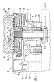
Die Erfindung zeigt in Figur 1 einen Schnitt durch eine teilweise fertiggestellte Antriebsvorrichtung, Figur 2 ein Einzelteil der erfindungsgemäßen Antriebsvorrichtung und Figur 3 die erfindungsgemäße Antriebsvorrichtung in zusammengebautem Zustand.The invention shows in Figure 1 a section through a partially completed drive device, Figure 2 a Item of the drive device according to the invention and Figure 3 shows the drive device according to the invention in assembled condition.
Im Ausführungsbeispiel ist die erfindungsgemäße
Antriebsvorrichtung 2 ausgebildet als eine
Antriebsvorrichtung für einen Scheibenwischer, zu dessen
Antrieb die Antriebsvorrichtung 2 eine teilweise
dargestellte Kurbel 3 eines nicht dargestellten
Kurbelgetriebes, das zu einem Wischerarm führt, in Drehung
versetzt.In the exemplary embodiment is the
Die Antriebsvorrichtung 2 hat ein Gehäuse 4 und gemäß der
Figur 3 einen Gehäusedeckel 5, einen nicht gezeichneten
Elektromotor zum Antreiben einer Schneckenwelle 6, ein mit
der Schneckenwelle 6 kämmendes Schneckenrad 7, eine mit dem
Schneckenrad 7 verdrehfest verbundene Schneckenradwelle 8,
im Gehäuse 4 befindliche Lagerbuchsen 9 und 10 für die
Schneckenradwelle 8 und eine Steuereinrichtung 11, die im
Beispiel ein mit dem Schneckenrad 7 verdrehfest verbundenes
Schaltrad 12 und stirnseitig des Schaltrades 12 und dabei
abgekehrt vom Schneckenrad 7 entfernt hier drei
magnetflußempfindliche Sensoren 13, 14, 15 auf einer
Sensorbrücke 16 aufweist.The
Die Sensorbrücke 16 ist beispielsweise gestaltet als eine
Leiterbahnplatte, die am Gehäusedeckel 5 befestigt sein
kann. Die Sensoren 13, 14 und 15 weisen hier nicht
dargestellte Lötfahnen auf, mittels denen die Sensoren 13
bis 15 an der Sensorbrücke 16 angelötet sein können. Die
Sensoren 13 bis 15 sind beispielsweise als Hall-Sensoren
ausgebildet und haben von der Schaltscheibe 12 einen
Mindestabstand. Damit dieser Mindestabstand erhalten bleibt,
ist außerhalb des Gehäuses 4 ein federnder
Axialsicherungsring 17 um die Schneckenradwelle 8 herum
angeordnet. Der Axialsicherungsring 17 weist federnde
Krallen 18 auf, die ein Herauswandern der Schneckenradwelle
8 aus dem Axialsicherungsring 17 und dabei eine Annäherung
des Schneckenrades 7 an die Sensoren 13 bis 15 vermeiden.
Zwischen den Axialsicherungsring 17 und das Gehäuse 4 ist
hier eine Anlaufscheibe 19 eingebaut, die beispielsweise aus
Federstahlblech besteht und verschleißmindernd wirkt, so daß
ein konstruktiv gewollter Abstand zwischen dem Schneckenrad
7 bzw. der Schaltscheibe 12 und den Sensoren 13 bis 15
ausreichend sicher erhalten bleibt. Eine solche
verschleißmindernde Maßnahme ist auch vorgenommen durch
Einsetzen einer zweiten Anlaufscheibe 20 zwischen einer Nabe
21 des Schneckenrades 7 und dem Gehäuse 4. Das Schneckenrad
7 und seine Nabe 21 sind hier aus thermoplastischem
Kunststoff gespritzt, wodurch eine verdrehfeste Verbindung
mit der Schneckenwelle 8 herstellbar ist durch Anordnung
einer Rändelung 22 oder einer alternativen Kordelung, in die
zur Bildung einer formschlüssigen Verbindung der
thermoplastische Kunststoff eindringt. Insoweit sind für den
zuständigen Fachmann die mechanischen Bauteile der
Antriebsvorrichtung 2 ausreichend beschrieben.The
In den Figuren 1 und 3 ist das Schaltrad 12 längsgeschnitten
dargestellt, wobei ersichtlich ist, daß ein Teil 21' der
Nabe 21 als ein Zentrierzapfen dient, der in eine Öffnung 23
des Schaltrades 12 hineinragt. Eine Draufsicht auf das
Schaltrad 12 mit seiner Öffnung 23 ist in der Figur 2
dargestellt. Beispielsweise ist der Umfang der Öffnung 23
unterbrochen von drei ungleich ausgebildeten Nuten 24, 25
und 26. In nicht dargestellter Weise kann das Teil 21' den
Querschnitten der Nuten 24, 25 und 26 angepaßte Vorsprünge
aufweisen, so daß diese Vorsprünge zusammen mit den Nuten
24, 25 und 26 eine Vielkeilverbindung bilden, die beim
Überschieben der Schaltscheibe 12 über das Teil 21' eine
drehwinkelkorrekte und auch seitenkorrekte Ausrichtung der
Schaltscheibe 12 zum Schneckenrad 7 und damit später zur
Kurbel 3 erzwingt insofern, als bei einer anderen
Ausrichtung das Schaltrad 12 nicht über das Teil 21'
steckbar ist. Die drei Nuten 24, 25 und 26 bewirken also
eine Codierung, wie sie beispielsweise prinzipiell bei
elektrischen Steckverbindern bekannt ist zur Vermeidung von
Fehlverschaltungen und Kurzschlüssen. In Figures 1 and 3, the
Wie aus den Figuren 1 und 3, die einen radialen Schnitt
durch das Schaltrad 12 zeigen, erkennbar ist, ist das
Schaltrad nach Art einer Ringscheibe, also im wesentlichen
dünn ausgebildet. Diese Ringscheibe ist beispielsweise
hergestellt aus Permanentmagnetpulver und einer
thermoplastischen Bindung. Damit diese Ringscheibe 12 die
ihr zugedachte Aufgabe der Signalerzeugung in wenigstens
einem der Sensoren 13 bis 15 erfüllen kann, ist sie zu
magnetisieren, wobei das Magnetisieren in Abhängigkeit der
durch einen Fahrzeugtyp vorgegebenen Verstellwegmaße
erfolgt. Je Fahrzeugtyp oder gar je Karosserietyp wird
deshalb die Magnetisierung nach einem angepaßten Muster
erfolgen. Ein Beispiel für ein solches Muster ist
dargestellt in der Figur 2 durch Anordnen einer
Magnetisierungsspule 30, also eines
Magnetisierungswerkzeugs, über dem Grundriß der Ringscheibe
12. Ausgehend von einem Plus-Anschluß hat die
Magnetisierungsspule 30 aufeinanderfolgend radiale
Drahtabschnitte 31 bis 39 und dazwischen konzentrische, also
bogenförmige Drahtabschnitte 40 bis 47. Wenn
Magnetisierungsstrom durch die Magnetisierungsspule 30
geleitet wird, so fließt dieser Magnetisierungsstrom in dem
radialen Drahtabschnitt 31 radial einwärts, also in Richtung
der Mittenachse der Ringscheibe 12. Dadurch ergibt sich nach
der "Rechtsschraube-Regel" bei 31 die dort mit N und S
bezeichnete Polanordnung und bei 32, 33, 34, 35, 36, 37 und
38 ergeben sich die jeweils dort angegebenen Polanordnungen.
Die Spule 30 kann in einem Spulenhalter 50 fixiert sein. Ein
solcher Spulenhalter 50 ist schematisiert in der Figur 1
dargestellt.As from Figures 1 and 3, a radial section
show by the
Ausgehend von der Figur 2 ist die Möglichkeit erkennbar, das
Schaltrad 12 nach einem vorgegebenen Muster zu
magnetisieren, ohne daß dabei das Schaltrad 12 mit der
Antriebsvorrichtung 2 vereinigt ist. Von dieser Möglichkeit
wird beispielsweise Gebrauch gemacht, wenn ein
unmagnetisierter Rohling eines solchen Schaltrades von einem
Vorratsspeicher bei der Montagestraße entnommen und auf dem
Weg zu einer Montagestation dieser Montagestraße
magnetisiert wird. Für diesen Fall bildet die durch die
Anordnung der Nuten 24, 25 und 26 erstellte Codierung die
Gewähr dafür, daß das Schaltrad 12 nur in der vorgeplanten
Ausrichtung entlang dem Teil 21' auf das Schneckenrad 7
absenkbar ist. Dort wird es dann beispielsweise mittels
Klebstoff festgehalten.Starting from FIG. 2, the possibility can be seen that
Die Alternative dazu ist in der Figur 1 dargestellt anhand
der mittels eines Spulenhalters 50 oberhalb der
Schaltscheibe 12 ausgerichteten Magnetisierungsspule 30.
Damit hierbei eine vorgebbare Drehausrichtung des
Magnetisierungsmusters relativ zu dem Schaltrad 12 und dabei
auch der Antriebsvorrichtung 2 zustandekommt, ist das
Gehäuse 4 der Antriebsvorrichtung 2 in eine
Aufnahmevorrichtung 51 eingesetzt. Die Aufnahmevorrichtung
51 weist zur Aufnahme eines aus der Antriebsvorrichtung 2
herausragenden Abschnittes der Schneckenwelle 8 eine
Aufnahmebohrung 52 auf und für die richtige Drehausrichtung
um die Aufnahmebohrung 52 besitzt das Gehäuse 4 einen
Ausrichtzapfen 53, der in eine Ausrichtnut 54 eintaucht, die
sich oben und dabei stirnseitig in einer zur
Aufnahmevorrichtung 51 gehörenden Säule 55 befindet.The alternative to this is shown in FIG. 1 using
which by means of a
Unter Verwendung dieser Aufnahmevorrichtung 51 und des dazu
geeignet ausgerichteten Spulenhalters 50 und dabei auch der
Spule 30 erfolgt die Magnetisierung unter gleichzeitiger
richtiger Ausrichtung des Magnetisierungsmusters, so daß
beim Beenden des Magnetisierens die Antriebsvorrichtung 2
fertig justiert ist bezüglich des Schaltrades 12. Wenn dann
der in der Figur 3 dargestellte Gehäusedeckel 5 mit der
daran befestigten Sensorbrücke 16 auf das Gehäuse 4
aufgesetzt ist, ist die Antriebsvorrichtung 2 komplett
montiert. Weil es technisch keine Schwierigkeit macht, die
Sensorbrücke 16 in vorbestimmter Weise an dem Gehäusedeckel
5 zu befestigen, ist also nach dem Befestigen des
Gehäusedeckels 5 die Antriebsvorrichtung 2 fertig und kann
danach zu einem Fahrzeug zwecks eines Einbauens verbracht
werden.Using this
Wie bereits erwähnt, ist die Erfindung beschrieben im
Zusammenhang mit einer Antriebsvorrichtung 2, die für einen
Scheibenwischer bestimmt ist und deshalb relativ einfach im
Aufbau ist. Die Erfindung ist aber auch anwendbar bei einer
solchen Antriebsvorrichtung, die zur Gattung der
Schiebedachantriebsvorrichtungen gehört. Diese Gattung ist
in der Beschreibungseinleitung ausgiebig erwähnt, so daß es
hier keiner weiteren Erläuterung anhand einer Zeichnung
bedarf. Im Fall der Anwendung der Erfindung bei einer
Schiebedachantriebsvorrichtung kommt es nicht darauf an, in
welcher Weise Antriebsmomente übertragende Getriebeelemente
ausgebildet sind. Auch kommt es nicht darauf an, welcher Typ
von Getriebe zum Drehen des Schaltrades 12 in Abhängigkeit
der Länge eines von einem Schiebedach zurückgelegten Weges
verwendet wird.As already mentioned, the invention is described in
Connection with a
Die Anwendung der Erfindung ist aber nicht auf das Antreiben von Scheibenwischern oder Schiebedächern beschränkt. Vielmehr kann die Erfindung auch Verwendung finden bei Fensterhebern, Lüftungsklappen, Schiebetüren, Fahrzeugsitzen und Lenkradanordnungen.However, the application of the invention is not to driving limited by windshield wipers or sunroofs. Rather, the invention can also be used with Window regulators, ventilation flaps, sliding doors, vehicle seats and steering wheel assemblies.
Claims (6)
- Drive device (2) for a part, movable between end positions, of a vehicle, having an electric motor with a shaft (8) extracting a torque from the drive device (2), and having a switching device, which serves to control and shut down the electric motor for at least one predetermined position of the movable part and has an indexing wheel (12) with at least one permanent magnet and at least one sensor (13, 14, 15) sensitive to magnetic fields, the indexing wheel (12) being coupled at least indirectly to the shaft (8) such that it can be rotated by at most 360° during movement of the part of the vehicle between two end positions, characterized in that the indexing wheel (12) is of disc-shaped construction and consists at least partially of magnetizable material, in that at least one sensor (13, 14, 15) sensitive to magnetic flux interacts with a surface of the indexing wheel (12) which is aligned perpendicular to an axis of rotation of the indexing wheel (12), at least one annular zone of the surface being magnetized in at least one region in the circumferential direction, and in that the indexing wheel (12) has magnetic poles (N and S or S and N) consecutively corresponding in the circumferential sense in this region of the annular zone.
- Drive device according to Claim 1, characterized in that the indexing wheel (12) has in a radially offset fashion at least one further magnetized annular zone and, assigned thereto, at least one further sensor (13, 14, 15) sensitive to magnetic flux.
- Drive device according to Claim 1 or 2, characterized in that emanating from a central opening (23) the indexing wheel (12) has a plurality of different grooves (24, 25, 26) which are a constituent of a coding which serves to install the indexing wheel (12) in the drive device (2) in the correct position.
- Method for producing a drive device (2) having an indexing wheel (12) made from a magnetizable material according to one of Claims 1 to 3, characterized in that the indexing wheel (12) is substantially magnetized according to a prescribed pattern directly before installation in the drive device (2).
- Method for producing a drive device (2) having an indexing wheel (12) made from a magnetizable material according to one of Claims 1 to 3, characterized in that the indexing wheel (12) is installed in an unmagnetized state in the drive device (2) and fastened therein, and in that thereafter the indexing wheel (12) is magnetized according to a prescribed pattern by means of a magnetizing device (30, 50).
- Method according to one of Claims 4 or 5, characterized in that the prescribed pattern is magnetized onto the indexing wheel (12) in a prescribed way with the aid of a magnetizing device running in the direction of rotation.
Applications Claiming Priority (3)
| Application Number | Priority Date | Filing Date | Title |
|---|---|---|---|
| DE19754843 | 1997-12-10 | ||
| DE19754843A DE19754843A1 (en) | 1997-12-10 | 1997-12-10 | Drive device for a part of a vehicle that can be moved between end positions and method for its production |
| PCT/DE1998/003175 WO1999029528A1 (en) | 1997-12-10 | 1998-10-30 | Drive device for a movable part that can be displaced between end positions in a vehicle and method for the production thereof |
Publications (3)
| Publication Number | Publication Date |
|---|---|
| EP0981457A1 EP0981457A1 (en) | 2000-03-01 |
| EP0981457B1 true EP0981457B1 (en) | 2003-05-02 |
| EP0981457B2 EP0981457B2 (en) | 2006-05-03 |
Family
ID=7851421
Family Applications (1)
| Application Number | Title | Priority Date | Filing Date |
|---|---|---|---|
| EP98959778A Expired - Lifetime EP0981457B2 (en) | 1997-12-10 | 1998-10-30 | Drive device for a movable part that can be displaced between end positions in a vehicle and method for the production thereof |
Country Status (7)
| Country | Link |
|---|---|
| US (1) | US6163125A (en) |
| EP (1) | EP0981457B2 (en) |
| JP (1) | JP2001515626A (en) |
| KR (1) | KR100570454B1 (en) |
| BR (1) | BR9807205A (en) |
| DE (2) | DE19754843A1 (en) |
| WO (1) | WO1999029528A1 (en) |
Cited By (1)
| Publication number | Priority date | Publication date | Assignee | Title |
|---|---|---|---|---|
| EP2378646A1 (en) | 2010-04-15 | 2011-10-19 | Brusa Elektronik AG | Method and device for magnetising permanently excited synchronous machines and rotor for such synchronous machines |
Families Citing this family (24)
| Publication number | Priority date | Publication date | Assignee | Title |
|---|---|---|---|---|
| DE19858630A1 (en) * | 1998-12-18 | 2000-06-21 | Bosch Gmbh Robert | Drive for adjustable vehicle part especially sliding roof, has circuit board at radial distance from driven element path greater than size of sensor, and magnetic flux guiding body between sensor and switching body |
| DE19937222C2 (en) * | 1999-08-06 | 2001-11-29 | Webasto Vehicle Sys Int Gmbh | Control device for an electric motor for an adjustable vehicle part |
| FR2802032B1 (en) * | 1999-11-18 | 2002-02-22 | Valeo Equip Electr Moteur | ELECTRIC MACHINES SUITABLE FOR USE IN A MOTOR VEHICLE ON THE ONE HAND AS A GENERATOR AND ON THE OTHER HAND AS AN ELECTRIC MOTOR FOR STARTING THE VEHICLE'S INTERNAL COMBUSTION ENGINE |
| FR2807231B1 (en) * | 1999-11-18 | 2002-06-07 | Valeo Equip Electr Moteur | ELECTRIC MACHINES SUITABLE FOR USE IN A MOTOR VEHICLE ON THE ONE HAND AS A GENERATOR AND ON THE OTHER HAND AS AN ELECTRIC MOTOR FOR STARTING THE VEHICLE'S INTERNAL COMBUSTION ENGINE |
| DE10014735A1 (en) * | 2000-03-24 | 2001-10-11 | Bosch Gmbh Robert | Electromotor for motor vehicle rear window wiper includes one-sided arrangement of gear elements, gear position sensor device, signal transmitter and PCB, to eliminate need to turn electric motor during manufacturing sequence |
| DE10134937A1 (en) * | 2001-07-18 | 2003-02-06 | Bosch Gmbh Robert | Gear drive unit with speed detection |
| US7009386B2 (en) * | 2002-01-02 | 2006-03-07 | Stoneridge Control Devices, Inc. | Non-contact position sensor utilizing multiple sensor elements |
| JP2003344100A (en) * | 2002-05-28 | 2003-12-03 | Niles Co Ltd | Rotation detector and method for manufacturing the same |
| DE10258036A1 (en) * | 2002-12-12 | 2004-06-24 | Robert Bosch Gmbh | Electric motor, in particular for a windshield wiper device and windshield wiper device, in particular for a motor vehicle |
| WO2004068679A1 (en) * | 2003-01-27 | 2004-08-12 | Hitachi, Ltd. | Electric motor unit with controller |
| DE10313226A1 (en) * | 2003-03-25 | 2004-10-07 | Robert Bosch Gmbh | Electric drive unit |
| DE102005005802B3 (en) * | 2005-02-09 | 2006-06-14 | Hübner GmbH | Sliding door system for vehicles has chain drive that exhibits transmission such that outgoing motion of carriage slows down with high torque and lateral motion of door leaf increases faster with low torque |
| SE528392C2 (en) | 2005-03-11 | 2006-10-31 | Atlas Copco Rock Drills Ab | Sensor installation in a gearbox for positioning |
| DE102005038050B4 (en) * | 2005-08-10 | 2009-09-24 | Küster Automotive Door Systems GmbH | Electric motor driven drive unit for motor vehicles |
| DE102005040647A1 (en) * | 2005-08-27 | 2007-03-08 | Valeo Systèmes d`Essuyage | Electromotive auxiliary drive e.g. windshield wiper drive, for e.g. road vehicle, has permanent magnet provided at shaft extension or at gearing unit, and magnetic sensors provided within bearing arrangement toward shaft axis |
| US8256161B2 (en) * | 2006-06-09 | 2012-09-04 | Mitsuba Corporation | Automatic opening/closing apparatus for vehicle |
| US7725231B2 (en) | 2006-09-11 | 2010-05-25 | Robert Bosch Gmbh | Method for displacing a movable part and sliding roof system for carrying out such a method |
| DE102008043214A1 (en) * | 2008-10-28 | 2010-04-29 | Zf Lenksysteme Gmbh | steering |
| EP2325426B1 (en) * | 2009-11-20 | 2015-06-17 | Aisin Seiki Kabushiki Kaisha | Driving device |
| US9073575B2 (en) * | 2010-05-12 | 2015-07-07 | GM Global Technology Operations LLC | Memory features for a manually adjustable apparatus |
| JP5600528B2 (en) * | 2010-09-03 | 2014-10-01 | 株式会社東海理化電機製作所 | Rotation angle detector |
| KR101490952B1 (en) * | 2013-12-23 | 2015-02-09 | 현대자동차 주식회사 | Apparatus of detecting position of rotating member and system of operating wiper |
| DE102018002158A1 (en) * | 2018-03-16 | 2019-09-19 | Paragon Ag | Sensor device for detecting a rotational position of a propeller shaft of body kinematics devices, e.g. from spoilers |
| US11722036B2 (en) * | 2021-06-14 | 2023-08-08 | Commercial Vehicle Group, Inc. | Wiper motors and methods of manufacture and use thereof |
Family Cites Families (15)
| Publication number | Priority date | Publication date | Assignee | Title |
|---|---|---|---|---|
| US4508998A (en) † | 1981-02-09 | 1985-04-02 | David H. Rush | Brushless disc-type DC motor or generator |
| JPS5830830A (en) * | 1981-08-13 | 1983-02-23 | Aisin Seiki Co Ltd | Driver for sun roof |
| DE3829405A1 (en) † | 1988-08-30 | 1990-03-08 | Webasto Ag Fahrzeugtechnik | Actuating device for parts of motor vehicles movable by electric motors |
| US4866357A (en) * | 1988-12-19 | 1989-09-12 | Ford Motor Company | Windshield wiper and control system |
| US5200729A (en) † | 1989-08-29 | 1993-04-06 | Yamamoto Electric Corporation | Permanent magnet and magnetization apparatus for producing the permanent magnet |
| DE4021973C1 (en) * | 1990-07-10 | 1992-01-02 | Webasto Ag Fahrzeugtechnik, 8035 Stockdorf, De | |
| FR2670286B1 (en) * | 1990-12-05 | 1993-03-26 | Moving Magnet Tech | MAGNETIC POSITION AND SPEED SENSOR WITH HALL PROBE. |
| DE4130065C2 (en) * | 1991-09-11 | 1993-12-02 | Licentia Gmbh | Electric wiper drive |
| DE4424633A1 (en) * | 1994-07-13 | 1996-01-25 | Bosch Gmbh Robert | Electric position drive, in particular for motor vehicle sunroofs |
| JPH0861976A (en) * | 1994-08-18 | 1996-03-08 | Asmo Co Ltd | Detecting device for position and load of moving body |
| JP3336141B2 (en) * | 1995-01-27 | 2002-10-21 | アスモ株式会社 | Moving object position detection device |
| JP3007838B2 (en) * | 1996-03-01 | 2000-02-07 | アスモ株式会社 | Moving body position detecting device and vehicle door |
| EP1009972B1 (en) * | 1996-05-11 | 2004-05-06 | Valeo Schalter und Sensoren GmbH | Device for detecting rotary movements |
| US6051899A (en) * | 1996-06-15 | 2000-04-18 | Itt Manufacturing Enterprises, Inc. | Drive mechanism |
| US5924324A (en) * | 1997-10-09 | 1999-07-20 | Ut Automotive Dearborn, Inc. | Movable gear drive windshield wiper |
-
1997
- 1997-12-10 DE DE19754843A patent/DE19754843A1/en not_active Withdrawn
-
1998
- 1998-10-30 KR KR1019997007178A patent/KR100570454B1/en not_active IP Right Cessation
- 1998-10-30 EP EP98959778A patent/EP0981457B2/en not_active Expired - Lifetime
- 1998-10-30 JP JP52961999A patent/JP2001515626A/en active Pending
- 1998-10-30 DE DE59808170T patent/DE59808170D1/en not_active Expired - Lifetime
- 1998-10-30 WO PCT/DE1998/003175 patent/WO1999029528A1/en active IP Right Grant
- 1998-10-30 US US09/341,761 patent/US6163125A/en not_active Expired - Fee Related
- 1998-10-30 BR BR9807205-6A patent/BR9807205A/en not_active IP Right Cessation
Cited By (2)
| Publication number | Priority date | Publication date | Assignee | Title |
|---|---|---|---|---|
| EP2378646A1 (en) | 2010-04-15 | 2011-10-19 | Brusa Elektronik AG | Method and device for magnetising permanently excited synchronous machines and rotor for such synchronous machines |
| WO2011128842A2 (en) | 2010-04-15 | 2011-10-20 | Brusa Elektronik Ag | Method and device for the magnetization of magnetic material pieces of a rotor in a permanently excited synchronous machine, and rotor for such a synchronous machine |
Also Published As
| Publication number | Publication date |
|---|---|
| KR100570454B1 (en) | 2006-04-13 |
| JP2001515626A (en) | 2001-09-18 |
| US6163125A (en) | 2000-12-19 |
| DE19754843A1 (en) | 1999-06-24 |
| EP0981457A1 (en) | 2000-03-01 |
| EP0981457B2 (en) | 2006-05-03 |
| WO1999029528A1 (en) | 1999-06-17 |
| KR20000070913A (en) | 2000-11-25 |
| DE59808170D1 (en) | 2003-06-05 |
| BR9807205A (en) | 2000-05-23 |
Similar Documents
| Publication | Publication Date | Title |
|---|---|---|
| EP0981457B1 (en) | Drive device for a movable part that can be displaced between end positions in a vehicle and method for the production thereof | |
| EP1660359B1 (en) | Drive device for window wipers with a parking position switch | |
| DE3730448C2 (en) | ||
| EP1070259B1 (en) | Rotation sensor | |
| WO1998040751A1 (en) | Motor with speed of rotation detected by a hall sensor | |
| DE112006002530T5 (en) | Windscreen wiper arrangement with direct drive | |
| DE102005040647A1 (en) | Electromotive auxiliary drive e.g. windshield wiper drive, for e.g. road vehicle, has permanent magnet provided at shaft extension or at gearing unit, and magnetic sensors provided within bearing arrangement toward shaft axis | |
| DE19518330A1 (en) | Electric window operating mechanism for motor vehicle | |
| DE102005019853A1 (en) | Tandem windshield wiper system for vehicle, has gear set that is coaxially disposed at longitudinal axis of motor and having output shaft that reduces rotational output speed of motor | |
| DE102012100829A1 (en) | Device for detecting the angular position of a shaft of an electric motor and windscreen wiper motor with a device for detecting the angular position | |
| EP1042146B1 (en) | Windshield wiper drive device | |
| DE102005019854A1 (en) | Tandem windshield wiper system for automotive vehicle, has bellcrank with central attachment point mounted to motor, and connecting arms disposed between lever arms of windshield assemblies and ends of bellcrank, respectively | |
| DE102005040646A1 (en) | Electric motor accessory drive system e.g. windscreen wiper drive system, for e.g. road vehicle, has magnetic sensors acting together with ring magnet for determining angle position of rotary motion of shaft of drive | |
| EP3254363A1 (en) | Drive unit for a wiper system | |
| DE19749009A1 (en) | Drive device with electric motor for automobile applications | |
| DE19746595A1 (en) | Drive unit with electric motor | |
| EP1114503B1 (en) | Commutator motor | |
| DE102019202115A1 (en) | Method for setting a sensor system of an electric motor and electric motor | |
| EP1312534A2 (en) | Steering wheel steering angle determination apparatus | |
| EP1057241B1 (en) | Drive device for an adjustable component of a vehicle | |
| DE10111400B4 (en) | Actuator for heating, ventilation or air conditioning flaps in a motor vehicle | |
| DE19653208B4 (en) | Process for the production of a permanently excited low-pole electric motor with a high-pole angular momentum encoder | |
| WO2006122523A1 (en) | Planar motor for driving an adjuster device on a motor vehicle | |
| WO2005085025A1 (en) | Wiper arm drive device | |
| EP1037776B1 (en) | Windshield wiper device |
Legal Events
| Date | Code | Title | Description |
|---|---|---|---|
| PUAI | Public reference made under article 153(3) epc to a published international application that has entered the european phase |
Free format text: ORIGINAL CODE: 0009012 |
|
| 17P | Request for examination filed |
Effective date: 19991217 |
|
| AK | Designated contracting states |
Kind code of ref document: A1 Designated state(s): DE ES FR GB IT |
|
| 17Q | First examination report despatched |
Effective date: 20020118 |
|
| GRAH | Despatch of communication of intention to grant a patent |
Free format text: ORIGINAL CODE: EPIDOS IGRA |
|
| GRAH | Despatch of communication of intention to grant a patent |
Free format text: ORIGINAL CODE: EPIDOS IGRA |
|
| GRAA | (expected) grant |
Free format text: ORIGINAL CODE: 0009210 |
|
| AK | Designated contracting states |
Designated state(s): DE ES FR GB IT |
|
| PG25 | Lapsed in a contracting state [announced via postgrant information from national office to epo] |
Ref country code: IT Free format text: LAPSE BECAUSE OF FAILURE TO SUBMIT A TRANSLATION OF THE DESCRIPTION OR TO PAY THE FEE WITHIN THE PRESCRIBED TIME-LIMIT;WARNING: LAPSES OF ITALIAN PATENTS WITH EFFECTIVE DATE BEFORE 2007 MAY HAVE OCCURRED AT ANY TIME BEFORE 2007. THE CORRECT EFFECTIVE DATE MAY BE DIFFERENT FROM THE ONE RECORDED. Effective date: 20030502 Ref country code: GB Free format text: LAPSE BECAUSE OF FAILURE TO SUBMIT A TRANSLATION OF THE DESCRIPTION OR TO PAY THE FEE WITHIN THE PRESCRIBED TIME-LIMIT Effective date: 20030502 |
|
| REG | Reference to a national code |
Ref country code: GB Ref legal event code: FG4D Free format text: NOT ENGLISH |
|
| REF | Corresponds to: |
Ref document number: 59808170 Country of ref document: DE Date of ref document: 20030605 Kind code of ref document: P |
|
| PG25 | Lapsed in a contracting state [announced via postgrant information from national office to epo] |
Ref country code: ES Free format text: LAPSE BECAUSE OF FAILURE TO SUBMIT A TRANSLATION OF THE DESCRIPTION OR TO PAY THE FEE WITHIN THE PRESCRIBED TIME-LIMIT Effective date: 20030813 |
|
| GBV | Gb: ep patent (uk) treated as always having been void in accordance with gb section 77(7)/1977 [no translation filed] |
Effective date: 20030502 |
|
| ET | Fr: translation filed | ||
| PLBQ | Unpublished change to opponent data |
Free format text: ORIGINAL CODE: EPIDOS OPPO |
|
| PLBI | Opposition filed |
Free format text: ORIGINAL CODE: 0009260 |
|
| PLAX | Notice of opposition and request to file observation + time limit sent |
Free format text: ORIGINAL CODE: EPIDOSNOBS2 |
|
| 26 | Opposition filed |
Opponent name: WEBASTO AG Effective date: 20040202 |
|
| PLBB | Reply of patent proprietor to notice(s) of opposition received |
Free format text: ORIGINAL CODE: EPIDOSNOBS3 |
|
| PUAH | Patent maintained in amended form |
Free format text: ORIGINAL CODE: 0009272 |
|
| STAA | Information on the status of an ep patent application or granted ep patent |
Free format text: STATUS: PATENT MAINTAINED AS AMENDED |
|
| 27A | Patent maintained in amended form |
Effective date: 20060503 |
|
| AK | Designated contracting states |
Kind code of ref document: B2 Designated state(s): DE ES FR GB IT |
|
| REG | Reference to a national code |
Ref country code: ES Ref legal event code: FD2A Effective date: 20031031 |
|
| ET3 | Fr: translation filed ** decision concerning opposition | ||
| PGFP | Annual fee paid to national office [announced via postgrant information from national office to epo] |
Ref country code: FR Payment date: 20131018 Year of fee payment: 16 |
|
| PGFP | Annual fee paid to national office [announced via postgrant information from national office to epo] |
Ref country code: DE Payment date: 20131217 Year of fee payment: 16 |
|
| REG | Reference to a national code |
Ref country code: DE Ref legal event code: R119 Ref document number: 59808170 Country of ref document: DE |
|
| PG25 | Lapsed in a contracting state [announced via postgrant information from national office to epo] |
Ref country code: DE Free format text: LAPSE BECAUSE OF NON-PAYMENT OF DUE FEES Effective date: 20150501 |
|
| REG | Reference to a national code |
Ref country code: FR Ref legal event code: ST Effective date: 20150630 |
|
| PG25 | Lapsed in a contracting state [announced via postgrant information from national office to epo] |
Ref country code: FR Free format text: LAPSE BECAUSE OF NON-PAYMENT OF DUE FEES Effective date: 20141031 |