EP0981173B1 - Schutzvorrichtung für eine mehrfach nachladbare elektrochemische Batterie - Google Patents
Schutzvorrichtung für eine mehrfach nachladbare elektrochemische Batterie Download PDFInfo
- Publication number
- EP0981173B1 EP0981173B1 EP98121497A EP98121497A EP0981173B1 EP 0981173 B1 EP0981173 B1 EP 0981173B1 EP 98121497 A EP98121497 A EP 98121497A EP 98121497 A EP98121497 A EP 98121497A EP 0981173 B1 EP0981173 B1 EP 0981173B1
- Authority
- EP
- European Patent Office
- Prior art keywords
- battery
- protective device
- contact
- housing
- membrane
- Prior art date
- Legal status (The legal status is an assumption and is not a legal conclusion. Google has not performed a legal analysis and makes no representation as to the accuracy of the status listed.)
- Expired - Lifetime
Links
- 230000001681 protective effect Effects 0.000 claims abstract description 162
- 239000012528 membrane Substances 0.000 claims description 101
- 239000000758 substrate Substances 0.000 claims description 32
- 239000000919 ceramic Substances 0.000 claims description 20
- 230000008859 change Effects 0.000 claims description 19
- 239000000463 material Substances 0.000 claims description 18
- 238000011156 evaluation Methods 0.000 claims description 8
- 238000007599 discharging Methods 0.000 claims description 2
- 238000005192 partition Methods 0.000 claims description 2
- 210000000056 organ Anatomy 0.000 abstract description 7
- 230000004075 alteration Effects 0.000 abstract 1
- 239000010410 layer Substances 0.000 description 25
- 230000009172 bursting Effects 0.000 description 21
- 229910000679 solder Inorganic materials 0.000 description 20
- 239000000126 substance Substances 0.000 description 10
- 239000000853 adhesive Substances 0.000 description 8
- 230000001070 adhesive effect Effects 0.000 description 8
- 238000009413 insulation Methods 0.000 description 8
- RTAQQCXQSZGOHL-UHFFFAOYSA-N Titanium Chemical compound [Ti] RTAQQCXQSZGOHL-UHFFFAOYSA-N 0.000 description 7
- 238000013461 design Methods 0.000 description 7
- 229910052719 titanium Inorganic materials 0.000 description 7
- 239000010936 titanium Substances 0.000 description 7
- 239000004020 conductor Substances 0.000 description 6
- 239000007789 gas Substances 0.000 description 6
- 238000001465 metallisation Methods 0.000 description 5
- 230000002441 reversible effect Effects 0.000 description 5
- PCHJSUWPFVWCPO-UHFFFAOYSA-N gold Chemical compound [Au] PCHJSUWPFVWCPO-UHFFFAOYSA-N 0.000 description 4
- 239000010931 gold Substances 0.000 description 4
- 229910052737 gold Inorganic materials 0.000 description 4
- 230000002427 irreversible effect Effects 0.000 description 4
- 229910052574 oxide ceramic Inorganic materials 0.000 description 4
- 239000011224 oxide ceramic Substances 0.000 description 4
- 229920001343 polytetrafluoroethylene Polymers 0.000 description 4
- 239000004810 polytetrafluoroethylene Substances 0.000 description 4
- 239000012790 adhesive layer Substances 0.000 description 3
- 229910010293 ceramic material Inorganic materials 0.000 description 3
- 239000012634 fragment Substances 0.000 description 3
- 230000006870 function Effects 0.000 description 3
- 239000011521 glass Substances 0.000 description 3
- 239000007943 implant Substances 0.000 description 3
- -1 polytetrafluoroethylene Polymers 0.000 description 3
- 230000008901 benefit Effects 0.000 description 2
- 239000003990 capacitor Substances 0.000 description 2
- 239000002131 composite material Substances 0.000 description 2
- 238000011109 contamination Methods 0.000 description 2
- 230000008878 coupling Effects 0.000 description 2
- 238000010168 coupling process Methods 0.000 description 2
- 238000005859 coupling reaction Methods 0.000 description 2
- 230000003247 decreasing effect Effects 0.000 description 2
- 230000001419 dependent effect Effects 0.000 description 2
- 239000012212 insulator Substances 0.000 description 2
- 230000007257 malfunction Effects 0.000 description 2
- 238000004519 manufacturing process Methods 0.000 description 2
- 229910052751 metal Inorganic materials 0.000 description 2
- 239000002184 metal Substances 0.000 description 2
- 231100000614 poison Toxicity 0.000 description 2
- 230000002829 reductive effect Effects 0.000 description 2
- 230000029058 respiratory gaseous exchange Effects 0.000 description 2
- 239000003440 toxic substance Substances 0.000 description 2
- 230000007704 transition Effects 0.000 description 2
- 229910018072 Al 2 O 3 Inorganic materials 0.000 description 1
- 239000004642 Polyimide Substances 0.000 description 1
- 229910000831 Steel Inorganic materials 0.000 description 1
- 229910001069 Ti alloy Inorganic materials 0.000 description 1
- 230000004913 activation Effects 0.000 description 1
- 238000013459 approach Methods 0.000 description 1
- 229920000249 biocompatible polymer Polymers 0.000 description 1
- 238000004891 communication Methods 0.000 description 1
- 230000006835 compression Effects 0.000 description 1
- 238000007906 compression Methods 0.000 description 1
- 238000010276 construction Methods 0.000 description 1
- 238000005520 cutting process Methods 0.000 description 1
- 238000011161 development Methods 0.000 description 1
- 230000018109 developmental process Effects 0.000 description 1
- 238000010586 diagram Methods 0.000 description 1
- 239000003814 drug Substances 0.000 description 1
- 229940079593 drug Drugs 0.000 description 1
- 239000012530 fluid Substances 0.000 description 1
- 230000005283 ground state Effects 0.000 description 1
- 239000011810 insulating material Substances 0.000 description 1
- 230000010354 integration Effects 0.000 description 1
- 230000003993 interaction Effects 0.000 description 1
- 239000007788 liquid Substances 0.000 description 1
- 230000009347 mechanical transmission Effects 0.000 description 1
- 230000003446 memory effect Effects 0.000 description 1
- 229910052758 niobium Inorganic materials 0.000 description 1
- 239000010955 niobium Substances 0.000 description 1
- GUCVJGMIXFAOAE-UHFFFAOYSA-N niobium atom Chemical compound [Nb] GUCVJGMIXFAOAE-UHFFFAOYSA-N 0.000 description 1
- 238000005457 optimization Methods 0.000 description 1
- TWNQGVIAIRXVLR-UHFFFAOYSA-N oxo(oxoalumanyloxy)alumane Chemical compound O=[Al]O[Al]=O TWNQGVIAIRXVLR-UHFFFAOYSA-N 0.000 description 1
- 230000036961 partial effect Effects 0.000 description 1
- 230000000149 penetrating effect Effects 0.000 description 1
- 239000004033 plastic Substances 0.000 description 1
- BASFCYQUMIYNBI-UHFFFAOYSA-N platinum Chemical compound [Pt] BASFCYQUMIYNBI-UHFFFAOYSA-N 0.000 description 1
- HWLDNSXPUQTBOD-UHFFFAOYSA-N platinum-iridium alloy Chemical compound [Ir].[Pt] HWLDNSXPUQTBOD-UHFFFAOYSA-N 0.000 description 1
- 229920000052 poly(p-xylylene) Polymers 0.000 description 1
- 229920001721 polyimide Polymers 0.000 description 1
- 229920001296 polysiloxane Polymers 0.000 description 1
- 230000036316 preload Effects 0.000 description 1
- 230000009467 reduction Effects 0.000 description 1
- 238000010079 rubber tapping Methods 0.000 description 1
- 238000007789 sealing Methods 0.000 description 1
- 238000000926 separation method Methods 0.000 description 1
- 230000008054 signal transmission Effects 0.000 description 1
- 230000011664 signaling Effects 0.000 description 1
- 125000006850 spacer group Chemical group 0.000 description 1
- 239000010959 steel Substances 0.000 description 1
- 229910052715 tantalum Inorganic materials 0.000 description 1
- GUVRBAGPIYLISA-UHFFFAOYSA-N tantalum atom Chemical compound [Ta] GUVRBAGPIYLISA-UHFFFAOYSA-N 0.000 description 1
- 238000003466 welding Methods 0.000 description 1
Images






Classifications
-
- H—ELECTRICITY
- H01—ELECTRIC ELEMENTS
- H01M—PROCESSES OR MEANS, e.g. BATTERIES, FOR THE DIRECT CONVERSION OF CHEMICAL ENERGY INTO ELECTRICAL ENERGY
- H01M50/00—Constructional details or processes of manufacture of the non-active parts of electrochemical cells other than fuel cells, e.g. hybrid cells
- H01M50/50—Current conducting connections for cells or batteries
- H01M50/572—Means for preventing undesired use or discharge
- H01M50/574—Devices or arrangements for the interruption of current
- H01M50/578—Devices or arrangements for the interruption of current in response to pressure
-
- H—ELECTRICITY
- H01—ELECTRIC ELEMENTS
- H01M—PROCESSES OR MEANS, e.g. BATTERIES, FOR THE DIRECT CONVERSION OF CHEMICAL ENERGY INTO ELECTRICAL ENERGY
- H01M50/00—Constructional details or processes of manufacture of the non-active parts of electrochemical cells other than fuel cells, e.g. hybrid cells
- H01M50/20—Mountings; Secondary casings or frames; Racks, modules or packs; Suspension devices; Shock absorbers; Transport or carrying devices; Holders
- H01M50/204—Racks, modules or packs for multiple batteries or multiple cells
- H01M50/207—Racks, modules or packs for multiple batteries or multiple cells characterised by their shape
- H01M50/216—Racks, modules or packs for multiple batteries or multiple cells characterised by their shape adapted for button or coin cells
-
- H—ELECTRICITY
- H01—ELECTRIC ELEMENTS
- H01M—PROCESSES OR MEANS, e.g. BATTERIES, FOR THE DIRECT CONVERSION OF CHEMICAL ENERGY INTO ELECTRICAL ENERGY
- H01M50/00—Constructional details or processes of manufacture of the non-active parts of electrochemical cells other than fuel cells, e.g. hybrid cells
- H01M50/50—Current conducting connections for cells or batteries
- H01M50/572—Means for preventing undesired use or discharge
- H01M50/574—Devices or arrangements for the interruption of current
-
- H—ELECTRICITY
- H01—ELECTRIC ELEMENTS
- H01M—PROCESSES OR MEANS, e.g. BATTERIES, FOR THE DIRECT CONVERSION OF CHEMICAL ENERGY INTO ELECTRICAL ENERGY
- H01M50/00—Constructional details or processes of manufacture of the non-active parts of electrochemical cells other than fuel cells, e.g. hybrid cells
- H01M50/50—Current conducting connections for cells or batteries
- H01M50/572—Means for preventing undesired use or discharge
- H01M50/574—Devices or arrangements for the interruption of current
- H01M50/583—Devices or arrangements for the interruption of current in response to current, e.g. fuses
-
- H—ELECTRICITY
- H01—ELECTRIC ELEMENTS
- H01M—PROCESSES OR MEANS, e.g. BATTERIES, FOR THE DIRECT CONVERSION OF CHEMICAL ENERGY INTO ELECTRICAL ENERGY
- H01M2200/00—Safety devices for primary or secondary batteries
- H01M2200/20—Pressure-sensitive devices
-
- Y—GENERAL TAGGING OF NEW TECHNOLOGICAL DEVELOPMENTS; GENERAL TAGGING OF CROSS-SECTIONAL TECHNOLOGIES SPANNING OVER SEVERAL SECTIONS OF THE IPC; TECHNICAL SUBJECTS COVERED BY FORMER USPC CROSS-REFERENCE ART COLLECTIONS [XRACs] AND DIGESTS
- Y02—TECHNOLOGIES OR APPLICATIONS FOR MITIGATION OR ADAPTATION AGAINST CLIMATE CHANGE
- Y02E—REDUCTION OF GREENHOUSE GAS [GHG] EMISSIONS, RELATED TO ENERGY GENERATION, TRANSMISSION OR DISTRIBUTION
- Y02E60/00—Enabling technologies; Technologies with a potential or indirect contribution to GHG emissions mitigation
- Y02E60/10—Energy storage using batteries
Definitions
- the invention relates to a protective device for a multi-rechargeable electrochemical Battery with a battery case, the protection device at least has a switching element which can be actuated by a detector element and which is designed or is adjustable, in the event of an impermissible operating state of the battery, recharging and / or prevent the same from being discharged.
- EP-A-0 360 395 and EP-A-0 370 634 it is known to provide electrochemical batteries with a switching element that when exceeded a certain still tolerated limit deformation of the battery housing an electrical Connection contact from an associated electrochemically active electrode preferably irreversibly separates in order to further deform the battery housing prevent.
- the battery housing includes an electrically conductive face closed cylindrical housing section which is in contact with an electrode, wherein the plate-shaped switching element is centered on the front by means of an electrical insulating adhesive is attached from the outside.
- the electrically conductive too Switching element forms an electrical one in its basic position over its outer edge Connection between the housing section and that in the center of the switching element arranged outwardly projecting electrical connection contact.
- the one that acts as a detector element bulges End face of the housing section to the outside, whereby the contact between the Housing section and the outer edge of the switching element and thus between one Electrode and the connection contact is interrupted.
- switching devices are called standard batteries of the type "D".
- the Curvature of the face from which the switching element interrupts the electrical contact, in this case is 0.76 mm to 1.8 mm. With a curvature of more than 1.8 mm usually with the leakage of chemicals from inside the battery case to calculate.
- EP-A-0 470 726 discloses an electrochemical battery with a cylindrical one Battery housing and a pressure membrane as a detector element, which is in the front of the battery housing is integrated and changes in pressure inside the battery housing bulges, whereby a plate-shaped, centrally connected to the pressure membrane Switching element an electrical contact between an electrode and a connection contact the battery reversibly or irreversibly interrupts.
- the battery housing comprises a cutting device actuatable by a pressure membrane, which at An electrical pressure exceeds a limit pressure inside the battery housing Irreversibly cuts the conductor, which connects the battery with a contact electrochemically active electrode connects.
- the invention specified in claim 1 is based on the object of a protective device for a multi-rechargeable electrochemical battery, which meets the specific requirements for parts of implantable devices.
- hermetic tightness is preferably hermetic gas tightness understood according to Mil-Std 883 D.
- This design ensures that at Use of rechargeable battery or accumulator in an electronic one Implant, which in turn is in a hermetically sealed and further biocompatible Housing is housed, in addition to liquid toxic substances also no gases can escape the protective housing. Such gases generally occur in small amounts Amounts even when the battery is used normally.
- Hermetic gas tightness of the protective housing will endanger the surrounding Electronics safely prevented; this means that the electronic circuits, in particular integrated circuits, can remain unprotected due to contamination even with the smallest quantities of escaping battery gases.
- the functional separation of the battery and battery case on the one hand and Protective housing and detector element with shape change impressed by the protective housing on the other hand allows an independent selection and optimization of the respective components.
- the requirements for dimensional tolerances of the battery case should not be very large as deviations are measured and can be compensated for on the protective housing during its manufacture.
- the implantable device can be, among other things, an active, electronic one Hearing implant, a pacemaker, a drug donor, one Act neurostimulator or the like.
- a recharge of the battery is preferably prevented by at least one Switching element is designed as a break contact, which is designed or adjustable, in the case of an impermissible one Operating state of the battery to electrically interrupt a recharging circuit, which can be fed by means of a charging device.
- At least one switching element can be designed as an opener, which is designed or adjustable, in the event of an impermissible operating state of the battery, the consumer circuit to interrupt electrically. So it is possible, for example in the event of a short circuit in the consumer circuit to prevent excessive electrical Power is withdrawn from the battery, which is also an impermissible operating state the battery, i.e. for example a volume expansion of the battery or one to a pressure rise inside the hermetically sealed protective housing Gas leakage from the battery housing. It is also conceivable that the Opener is arranged so that it simultaneously with the consumer circuit Reload circuit interrupts.
- At least one switching element is as Closer trained, which is designed or adjustable, in the case of an impermissible Operating state of the battery, the recharge circuit that can be fed by means of a charging device to short-circuit electrically, causing a further energy supply to the battery is interrupted.
- At least one switching element which is designed as a make contact which is designed or adjustable, in an impermissible operating state to short-circuit the battery electrically.
- Such a closer is particularly in serial coupling with an overcurrent fuse that makes a current in one Interrupt recharging and / or a consumer circuit of the battery irreversibly can.
- the overcurrent fuse can be designed as a fuse, which at Short circuit is blown by the residual energy stored in the battery. If the energy is not sufficient for this, the battery can be completely discharged.
- at least one overcurrent protection device switches the current in Reloading and / or a consumer circuit is only limited, advantageously the overcurrent protection is designed as a PTC resistor, the resistance of which increasing temperature rises.
- the switching elements can basically a circuit in which they are integrated interrupt reversible or irreversible. Reversible switching elements offer the Advantage that you can function non-destructively, for example, in the assembled Check condition in interaction with other components of the protective device can.
- the shape change impressed on the battery usefully actuates at least one switching element mechanically.
- a direct mechanical actuation of the switching element by the Changing the shape of the detector organ is particularly reliable because it is forced works without being dependent on non-mechanical transmission elements.
- At least one switching element by means of a change in shape of the detector electronics detecting electronics can be actuated.
- One will be advantageous electrical strain gauge used which changes the shape of the detector organ detected and with a change in an electrical quantity by the evaluation electronics is monitored, answers. Is it the electrical strain gauge a passive system, it can change the shape of the detector organ into a change its electrical resistance (strain gauge), its inductance or its Convert capacity.
- an active electrical strain gauge can be used which, e.g. a piezo element, with a charge change on a reacts on the strain gauge applied by the detector element.
- the detector element is part of the protective housing and in particular designed as an archable membrane, which in particular a Forms outer or partition wall of the hermetically sealed protective housing. This allows one space-saving construction and a predictable change in shape of the Detector organ when the pressure in the protective housing rises.
- the particularly critical thickness of an implantable device Protective housing can be reduced to a minimum if at least one membrane is integrated into a side wall of the hermetically sealed protective housing, the Direction of curvature of the membrane substantially perpendicular to the smallest extension of the Battery runs.
- the cover or bottom of the protective housing provided below the same then remain usefully free of detector and switching elements, so that the thickness of the Protective housing only slightly exceeds that of the battery.
- a redundant one Protection against an impermissible operating state of the battery arises if
- two membranes are provided, one of which is part of one Closer trained and by means of this membrane in an impermissible operating state the battery has a pair of contacts of the closer that can be electrically short-circuited.
- the second membrane can be formed as part of an opener, by means of this a second pair of contacts when the battery is in an impermissible operating state the opener can be disengaged electrically.
- the hermetically sealed design of the protective housing and a simple one Building the same is when the battery with both on the battery case located contacts with electrically insulated areas of the Protective housing is contacted, the electrically insulated areas of the protective housing electrically conductive and with a recharging and / or consumer circuit are electrically connected.
- the dimensions of the one provided in the protective housing, preferably one insulating material formed ceramic material can be minimized if at least one connection contact of the battery housing has a hermetic sealed, electrically insulated bushing with a reference to the protective housing Reloading and / or consumer circuit is electrically connected.
- the contact pins are expedient in the ceramic substrate and this in one Outer wall of the protective housing hermetically sealed by means of a material connection, preferably a solder joint, in particular a gold solder joint, added.
- the metallic receptacle with an outer wall the protective housing is also cohesively connected.
- Welded connection can be used.
- the protective housing as a whole is designed to be biocompatible, this can be done directly be implanted and with permanently connected or detachable electrical cables connected to the consumer, regardless of where they are implanted is, as is also the same in the German patent application filed in parallel the applicant under the title "Power supply module for an implantable Device ".
- materials for the biocompatible protective housing come preferably titanium, titanium alloys, niobium, tantalum, implantable steels or a composite of these or other implantable metallic with ceramic materials such as aluminum oxide ceramics are considered, with a casing the entire protective housing with a biocompatible polymer, such as Silicone, polytetrafluoroethylene (PTFE), polymethane, parylene or the like, can be useful.
- the position of the switching elements 44, 46, 48 and 50 shown in FIG. 1 corresponds to one Home position in normal operation. In the event of an impermissible operating state of the Battery 10 is actuated at least one of these switching elements.
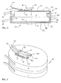
- FIGS. 2 to 4 A first embodiment of a protective device is shown in FIGS. 2 to 4 shown and includes a hermetically sealed protective housing 54 with a cup-shaped cover 56 and a likewise cup-shaped bottom 58.
- a hollow cylindrical side wall 60 the cover 56 is welded to a cover plate 62, which as the archable membrane Detector organ of the protective device forms.
- the floor 58 is one hollow cylindrical side wall 64 and a base plate 66 welded to it educated.
- the battery 10, which is a conventional rechargeable button cell acts, is received inside the protective housing 54, the positive Connection contact is tapped from the battery housing 12 via a contact tab 68, which is in contact with the inside of the side wall 60.
- the negative connection contact the battery 10 is from an end face 71 of the battery housing 12 by means of a Tapped tab 70 and guided from the inside to the side wall 64, one Recess 74 in the edge area of the base plate 66 enables the end face 71 of the battery case despite laying the contact tab 70 on the large area Base plate 66 rests.
- An insulation tube pushed over the contact tab 70 73 prevents electrical contact between the contact tab 70 and the positive connection contact of the battery 10.
- Both the cover 56 and the bottom 58 are made of an electrically conductive, against emerging from the battery housing Chemical-resistant material (such as titanium), and exhibit electrical connections 76 and 78, which correspond to connections 16 and 18 according to FIG. 1 correspond.
- the Closer 86 a flexible contact carrier 92, for example made of polyimide, the Has the shape of an approximately rectangular thin-walled plate, the short side of which is U-shaped Has incision, so that two spring arms 102, 104 arise.
- a flexible contact carrier 92 for example made of polyimide
- the Has the shape of an approximately rectangular thin-walled plate, the short side of which is U-shaped Has incision, so that two spring arms 102, 104 arise.
- 92 metallizations 94 on the upper side of the contact carrier attached, which extend into the spring arms 102 and 104, where on the Metallizations 94 each over a section of a platinum wire as contact 106 or 108 a solder joint 109 is soldered.
- a contact plate 96 and 98 Near the second short side of the Contact carrier 94 is a contact plate 96 and 98, respectively, by means of a solder layer 100 connected to one of the two metallizations 94.
- the contact plates 96 and 98 each have a terminal 112 or 114, so that the terminal 112 is electrically connected to the Contact 106 and terminal 114 is electrically connected to contact 108.
- a contact bridge 110 In A short distance above the contacts 106 and 108 is a contact bridge 110 arranged with which the contacts 106, 108 can be brought into contact with them to short-circuit electrically.
- the flexible contact carrier 92 is over a multi-layer Structure connected to the cover plate 62 such that the contacts 106, 108 in the middle are arranged above the cover plate 62 and in plan view along a The axis of symmetry of the round cover plate 62 runs. As shown in Fig.
- the contact tab 68 can be designed as a fuse, which the electrical Connection between the positive connection contact of the battery housing 12 and interrupts terminal 76 when the current flowing across them reaches a limit exceeds.
- one of the cover plates 62 must face End face 72 of the battery housing 12 and the cover plate 62 insulation is provided his.
- Both membranes 134 and 138 are made made of electrically conductive material, the contact membrane 134 with their Top side opposite the cover 120 arranged adjacent by means of an insulating layer 148 is electrically insulated and via a metallization 132, a via 130 and a solder layer 128 to the electrical potential of the ground 118 brought.
- the battery 10 is from the bottom 118, the bottom of the insulating ring 122 and the membrane 138 hermetically sealed, and their positive connection contact is connected to the inner base of the bottom 118 via the end face 72.
- a Spring 124 is between a shoulder of the battery case 12 and the Transition area between the insulating ring 122 and the side wall of the bottom 118 arranged and used for centering and backlash-free abutment surface 72 of Battery housing 12 on the base of the bottom 118.
- the spring 124 is at the same time in electrical contact with the side wall of the bottom 118, the solder layer 128 and the positive connection contact of the battery 10, which extends into the range of Extends shoulder against which the spring 124 abuts.
- the negative connection contact of the Battery 10 is on the end face 71 of the battery housing 12 and an optional one Spring 140 contacts the underside of diaphragm 138.
- a metallization 142 on the bottom of the insulating ring 122, a via 144 through the insulating ring 122 and a solder layer 146 close the electrical connection between the Membrane 138 and the cover 120, of which the negative potential via a Terminal 152 is tapped.
- a connector 150 on the outer side wall of the Bottom 118 serves to tap the positive potential of the battery 10.
- the membrane 138 with the negative terminal contact of the battery 10 in Connection is, that of the membrane 138 in one of the thickness of the insulating ring 122nd appropriate distance located contact membrane 134 with the positive Contact of the battery 10 contacted.
- This distance is such that at an impermissible operating state of the battery 10 of the membrane 138 a curvature is impressed, which is sufficient with the contact membrane 134 in electrically conductive To come into contact so that the battery 10 is electrically short-circuited.
- a portion of the solder joint 146 may be sized as a fuse, which irreversibly burns out if a recharge or discharge current exceeds a predetermined one Limit exceeded. Another supply and delivery of energy via the connections 150, 152 is thus prevented.
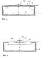
- FIGS. 6 and 7 has a third embodiment of a protection device a protective housing 154, the electrically conductive bottom of which is a side wall 156 in the form of a tube section, the end face of a base plate 158th is closed.
- a circumferentially closed weld 160 connects the Base plate 158 with the side wall 156.
- a ceramic insulating ring 162 is fixed over a solder layer 164, which has a round one Breakthrough with an inner diameter that is smaller than the inner diameter the side wall 156, with one towards the bottom plate 158 facing underside of the insulating ring 162 a spanning the breakthrough Membrane 166 made of electrically conductive material is attached and a hermetic dense interior is created.
- the battery 10 is accommodated in this interior such that their positive connection contact by means of the end face 72 in electrical Contact is made with the base plate 158.
- Weld spot 165 between the end face 72 and the base plate 158 guarantees one Contact with the lowest contact resistance and a defined position of the battery 10 with reference to the base plate 158.
- a Solder connection or an electrically conductive adhesive connection can be provided.
- the negative potential of the battery 10 is from the bottom 71 to the bottom Membrane 166 brought up, wherein a conductive adhesive can be provided to the To minimize contact resistance.
- the battery is advantageously located with its end faces 71, 72 slightly prestressed between the membrane 166 and the base plate 158.
- An electrically conductive contact membrane 168 with a central, downward facing Contact point 170 is connected to the top of the insulating ring 162 and spanned its breakthrough.
- the contact membrane 168 is inward resiliently bulged onto the membrane 166 and is in contact with the contact point 170 in electrical contact with the membrane 166. In this position the contact membrane 168 can be used to supply and deliver energy to and from the battery 10 the contact membrane 168 electrically connected terminal 174 and one with the Outside of the side wall 156 contacted connection 172 take place. It comes to an inadmissible operating state of the battery 10, the membrane 166 and with this bulges the contact membrane 168 so far outwards that the contact membrane 168 jumps outwards beyond an unstable equilibrium position and the electrical contact between the two membranes 166, 168 also interrupted remains when the membrane 166 returns to its starting position according to FIG. 6 should come back.
- a fourth embodiment of one in FIGS. 8 and 9 illustrate protection device has a protective housing, which differs from the protective housing 154 in the essentially only by the design of the membranes 166, 168 and their electrical Contacting differs.
- a membrane 176 corresponding to membrane 166 carries a contact spring labeled 180 in the center on its upper side a pin 182 and a spring plate 184.
- the cylindrical pin 182 is with a End face on the membrane 182, on which it is approximately perpendicular with its longitudinal axis stands, fixed and connected with its second end face to the spring plate 184.
- the pin 182 penetrates a breakthrough in a contact membrane 178, which the Corresponds to the contact membrane 168 of the protective housing 154, the spring plate 184 in 8 with a near its outer edge located contact surface 185 facing the upper side of the contact membrane 178 is in electrically conductive contact with the contact membrane 178.
- the membranes 176, 178 run approximately parallel, and the contact surface 185 rests resiliently biased against the contact membrane 178.
- the membrane 176 is curved outwards Direction imposed on the contact membrane 178, which is essentially not deformed and maintains its position.
- the curvature of the membrane 176 is sufficient Lift contact surface 185 from the contact membrane 178 and the electrical Reversible contact break is not so large that the top of the Membrane 176 comes into contact with the underside of the contact membrane 178.
- Around to ensure the latter even with an even greater curvature of the membrane 176 is the Provide the underside of the contact membrane 178 with an insulating layer 186.
- a fifth embodiment of a protective device comprises a Protective housing 190 with a one-piece cup-shaped bottom 192, also one cup-shaped cover 194 and a membrane 196, which is by means of a welded connection 198 on the mutually facing end faces of the bottom 192 and the lid 194 is connected to these, the bottom 192, the lid 194 and the membrane 196 preferably consist of the same electrically conductive material.
- the Membrane 196 divides the protective housing 190 horizontally into an upper one Cover area and a lower, hermetically sealed space that the battery 10 so records that your positive connection contact with a conductive adhesive 200 low contact resistance tapped over the end face 72 and with one of the Membrane 196 facing inside of the bottom 192 is contacted.
- an insulator 218 is applied, which prevents the negative terminal contact or pole of the battery 10 in contact with the membrane 196 comes.
- the negative potential of the battery is at an adjacent face 71 Side wall of the battery housing 12 from the negative connection contact via a Contact spring 212 tapped and by a hermetically sealed against a side wall of the bottom 192 electrically insulated bushing 214 through the side wall connected to a terminal 216 therethrough.
- On top of the membrane is 196 In the center, a plunger 222 is attached, which projects into an opening in the cover 194. Is located a short distance above an upper edge of the plunger 222 a bursting element spanning the breakthrough, identified overall by 204.
- This comprises a substrate on its side facing the top of the cover 194 206 with a conductive layer 208.
- the substrate 206 can be a ceramic, act, for example, oxide ceramics, a glass or the like.
- the conductive layer 208 is on one side of the opening in the cover 194 with this via a contact tab 202 contacted and on an opposite side of the opening with one Provide connection 210, from which the positive potential of the battery 10 is tapped becomes.
- a gap 220 between the insulator 218 on the end face 71 of the battery 10 and the membrane 196 prevents the membrane 196 from bulging at a small extent the battery 10, e.g. due to temperature increase.
- the membrane 196 With an impermissible Operating state of the battery 10, however, is the membrane 196, be it through Volume increase of the battery 10 and / or leakage of chemicals from the inside the battery 10 with the result of an increase in pressure in the hermetically sealed Battery housing of the protective housing 190, a curvature that is embossed is sufficient that the plunger 222 destroys the bursting element 204 so that the conductive layer 208 between the contact tab 202 and the terminal 210 is irreversibly interrupted.
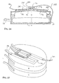
- a sixth embodiment has a protective device a protective housing 224 with a flat electrically conductive bowl-shaped Floor 226 on, with its upward-facing end face with interposition a ceramic insulating ring 229 is connected to a side wall 228, which has the shape of a pipe section. Sidewall 228 is at its top End face hermetically sealed with an electrically conductive membrane 230. On the upward facing outer side of membrane 230 is an insulating layer 232 and an electrically conductive, brittle bursting bursting layer 234 is applied thereon.
- the bursting layer 234 is in the area of the side wall 228 at a first point above a Contact 236 electrically conductive with the membrane 230 and on a second, diametrically opposite point connected to a terminal 238, the Bursting layer 234 extends in strips between these two locations.
- the Terminal 238 is used to tap the positive potential of the battery 10, which from Protective housing 224 is added.
- the positive contact of the Battery 10 from a side wall of battery housing 12 by means of a contact tab 242 tapped, the electrical via spot welds 244 and 246 Forms contact with the inside of the side wall 228.
- the negative connection contact the battery 10 is positioned centrally on the end face 71
- Spot weld connection 248 communicates with the inside of bottom 226 and is accessible from outside the protective housing 224 by means of a connection 240.
- spot weld connections 244, 246 and 248 for example solder connections or electrically conductive adhesive connections are provided could be.
- a seventh embodiment of a protective device is shown in FIG. 12 and includes a protective housing 252 which is substantially different from the protective housing 224 only by designing the bottom 226 and tapping the positive Terminal of the battery 10 differs.
- the protective housing 252 has one Bottom 254, the side walls of which extend up to and with the membrane 230 are hermetically sealed, so that the insulating ring 229 of the protective housing 224 eliminated.
- the positive connection contact of the battery 10 is via a contact tab 258 tapped from a side wall of the battery housing 12, by means of a hermetic sealed passage insulated from the side wall of the bottom 254 260 out through the side wall and from a contact tab 262 in Connected to the electrically conductive burst layer 234, which by a Insulating layer 255 completely insulated from membrane 230 and bottom 254 is.
- An insulating layer 256 clad the interior of the protective housing 252 in the area of the Membrane 230 and the side walls of the bottom 254 and prevents one electrical contact between the positive connection contact of the battery 10 and the Membrane 230 or the side walls of the bottom 254.
- FIGS. 13 and 14 uses an eighth embodiment of one Protection device a modified protective housing 264, which largely the Protective housing 54 of FIGS. 2 to 4 corresponds, but not its switching element 86 used and in which the tap of the positive terminal of the battery 10 in modified form takes place.
- a rectangular burst strip 266 is over adhesive bonds 268 and 270 each in the outer third of its longer side on the Cover plate 62 of protective housing 264 coupled at a predetermined distance from the outside, so that a bridging zone between the adhesive bonds 268 and 270 272 arises.
- a line of symmetry toward the longer side of the burst strip 266 runs essentially parallel to a center line of the round Cover plate 62, and a center of the bridging zone 272 is above of the center of the cover plate 62.
- On an upper side of the bursting strip 266 is one Conductor layer 276 applied, which extends over almost the entire top of the The bursting strip 266 extends in the region of the one short side of the bursting strip by means of a contact tab 284 with the cover plate 62 and in the area of the others short side is contacted with a connector 286. So there is an electrical connection between terminal 286 and the positive terminal contact of the battery 10 manufactured.
- a predetermined breaking point is provided in the form of a perforation 274.
- the predetermined breaking point can naturally also in another suitable way, for example by notches, scratches or tapering the bursting strip 266.
- Adjacent to perforation 274 is a wire section as a short-circuit contact 278 by means of a solder connection 280 fixed, over which a counter contact 282 is at a predetermined distance.
- the counter contact 282 stands over a contact tab 288 with the side wall 64, i.e. with the negative connection contact of the battery 10, in electrical contact.
- the cover plate 62 As an archable membrane a curvature is embossed, which on the adhesive connections 268, 270 on the Transmits bursting strip 266, which breaks along perforation 274 according to FIG. 14.
- the Short circuit contact 278 is pressed against counter contact 282, and the short circuit current between the positive and negative connection contacts of the battery 10 is sufficient, a possibly remaining conductive layer fragment 290, which is the breaking point at least partially overstretched to blow. This is the tap of the positive Potential of the battery 10 irreversibly interrupted via the connection 286.
- the predetermined geometry of the bursting strip 266 must be adhered to very precisely become.
- Glass for example, is used as the material for the bursting strip 266 or ceramic, it may be advantageous to give the bursting strip 266 a mechanical preload, which the distance of the fracture bank after the The breaking point increases.
- the bursting strip 266 can be used as a composite element of at least one glass or ceramic material and at least one Metal that are glued or soldered together.
- a Biasing strip 266 can also be preloaded using a metal can be induced with shape memory (memory effect).
- the bursting strip 266 from a piezoelectric material or at least to provide such a layer. With deformations of the bursting strip 266, which do not lead to its breakage, that is to say not yet inadmissible Signaling the operating state of the battery 10 can from the piezoelectric Electrical information supplied in the form of charge changes from the converter
- Optional evaluation electronics 52 can be tapped, for example, to a Opener 48 or 50 of Fig. 1 corresponding switching element to operate and a Interrupt recharging or discharging of the battery 10 before the battery one impermissible operating state reached.
- Multi-redundant protection is not required, it is also conceivable on the short-circuit contact 278 and the counter contact 282 to be completely dispensed with, only the irreversible opening function of the burst strip 266 and to interpret it in such a way that it is ensured in any case that when the strip 266 breaks, no conductive layer fragment 290 remains.
- FIG. 15 A ninth embodiment of a protective device is shown in FIG. 15 and differentiates it differs from the embodiment of FIGS. 2 to 4 essentially only that to increase redundancy, a strain gauge 292 meandering on the Top of the cover plate 62 is applied.
- the strain gauge 292 experiences at Curvature of the cover plate 62 a change in shape, resulting in a change in its electrical resistance leads, which leads via connections 294 and 296 of the Evaluation electronics 52 detected and for example for actuating further switching elements is used, for example for an electrically operated closer, which from Protective housing can be placed away and the function of the closer 46 or corresponds to the opener 50 of FIG. 1.
- the evaluation electronics 52 can also not activate the warning device shown, which notifies a user of the malfunction of the Battery 10 notifies.
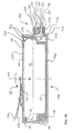
- a protective housing 298 shown in FIG. 16 already includes this in connection with the protective housing 54 of FIGS. 2 to 4 described switching element 86 and differs from the protective housing 54 essentially only in the following design features:
- a metallic floor, preferably made of titanium designed cup-shaped, with a hollow cylindrical side wall 300 on its lower End face is closed in one piece by means of a base plate 302.
- On an upper one The end face of the side wall 300 is a cover plate designed as an archable membrane 304 hermetically welded, which is also preferably made of titanium.
- a cup-shaped receptacle 306 is in the interior of the protective housing 298 added that its cylindrical side wall one the inner diameter of the Side wall 300 has the corresponding outer diameter and its base plate on the Base plate 302 rests.
- the inside diameter of the receptacle 306 is that Adapted battery housing 12, the battery 10 with its end face 72 from the inside abuts the bottom plate of the receptacle 306 and in the radial direction within the Protective housing is centered.
- the receptacle 306 consists of an electrical insulating plastic material, for example polytetrafluoroethylene (PTFE), and isolates the positive connection contact of the battery 10 from the metallic protective housing.
- PTFE polytetrafluoroethylene
- the receptacle 306 is on the outside of its side wall with a recess 308 provided and so inserted in the protective housing 298, the one in the radial
- the opening 310 introduced in the side wall 300 faces.
- the O-ring 82 is in the corner area between the side wall 300 and the cover plate 304 places and supports against a shoulder of the battery case 12, which he biased down towards the bottom plate 302 to prevent it from between the end face 72, the base plate of the receptacle 306 and the base plate 302 form unwanted column. So that there are no two separate volumes build up inside the protective housing 298, the O-ring 82 is circumferential not closed, but has a radial gap.
- the cylindrical opening 310 in the side wall 300 is surrounded on the outside of the side wall 300 by a cylindrical flat surface 312, into which an outwardly facing shoulder 314 of a socket-shaped, metallic receptacle 316, preferably made of titanium, is fitted and hermetically sealed.
- the receptacle 316 is part of a bushing designated overall by 315, which further comprises a ceramic substrate 318, for example made of Al 2 O 3 , and metallic contact pins 322, 324, the latter preferably consisting of a platinum-iridium compound.
- the outer diameter of the cylindrical substrate 318 is adapted to the inner diameter of the receptacle 316 and inserted into the receptacle 316 up to a collar on the inner wall thereof, which is located in the axial direction on the side of the receptacle 316 facing the shoulder.
- the substrate 318 projects above the receptacle 316 and is hermetically sealed to it via a gold solder connection 320.
- the contact pins 322 and 324 which are shown in FIG. 16 in a position rotated by 90 ° about the axis of the receptacle 316, penetrate the substrate 318 in the axial direction and are hermetically sealed in the same way by means of a gold solder connection 326.
- the pin 322 is contacted via a contact tab 332 with the positive connection contact of the battery 10 in the region of the shoulder of the battery housing 12 on which the O-ring 82 is supported. This is oriented such that the contact tab 332, like a contact tab 330, which forms a current path between the negative connection contact of the battery 10 and the contact pin 324, are guided through the radial gap of the O-ring 82. Both contact tabs 330, 332 are surrounded by an insulation tube 334.
- a gap between the end face 71 of the battery 10 and the underside of the cover plate 304 which gap compensates for natural breathing of the battery housing 12.
- the negative connection contact of the battery 10 touches the cover plate 304 from below, as a result of which the metallic components 300, 302, 304 and 316 of the protective housing 298 are connected to the negative potential of the battery 10.
- a solder bridge 328 is provided on the leadthrough 315, which extends between the contact pin 324 and the receptacle 316. Outside the protective housing 298, the positive and negative connection contacts of the battery 10 are tapped via connections 338 and 336, respectively.
- the protective housing 298 can be smaller compared to the protective housing 54 Manufacture effort, since the bottom of the protective housing 298 is made in one piece and no ceramic insulation ring 80 is used.
- the particularly critical metal-ceramic transition is reduced to a minimum and to a separately manufactured and restricted part 315 to be tested. This contributes significantly to a higher compressive strength of the protective housing 298.
- a protective case 340 may be toward the smallest Expansion of the battery 10 seen instead of a cylindrical one, for example have an approximately teardrop-shaped cross-sectional shape.
- the side wall of a segment 342 in Form a three-quarter circle and two tangent to both sides of the three-quarter circle subsequent linear segments 344 and 346, the latter close with a rounding between them.
- the sidewall is metallic, preferably made of titanium and forms together with one one-piece base plate has a cup-shaped base for receiving the battery 10.
- a not shown, also preferably made of titanium cover plate is with the upper end face of the side wall hermetically sealed. The clarity half of the wall thickness of the segments 342, 344 and 346 is shown enlarged.
- the battery 10 is inside the protective case 340 by not shown Centering means fixed, with at least the positive connection contact of the battery 10 is electrically insulated with respect to the cup-shaped bottom and the cover plate.
- An implementation designated 348 in total differs from the implementation 315 of FIG. 16 essentially by dispensing with the receptacle 316, so that a ceramic substrate 350 is not in the receptacle but directly in the side wall of the protective housing 340 is hermetically sealed, which is preferable Gold solder is used. Ceramic substrate 350 is in linear segment 344 soldered in, but it is also possible for the former in the circular segment 342 accommodate.
- Metallic contact pins 354 and 356 are used for separate implementation of the negative and the positive contact of the battery 10 and are in ceramic substrate 352 hermetically sealed. Regarding the preferred The choice of materials for the contact pins 354, 356 and the substrate 350 is based on the explanations referenced for implementation 315.
- One of the Solder bridge 328 (see Fig. 16) similar electrical connection between the Contact pin 354 and segment 344 may be provided to define the housing to put negative potential.
- a cylindrical opening in segment 346 takes place by means of a solder connection ceramic substrate 358, which is penetrated by two contact pins 360 and 362 is, which are received in the substrate via a solder connection and this axially protrude on both sides.
- the breakthrough in segment 346 is on the outside by a metallic membrane 364 hermetically sealed, the membrane 364 in Ground state, i.e. if the pressure inside the protective housing is not excessively high 340, with its inside facing the inside of the protective housing 340 on the Contact pins 360 and 362 are applied with a defined bias and these are electrical combines.
- An opening 366 in the substrate 358 ensures that in the axial direction both sides of the substrate, i.e. on the side of the substrate facing the battery 10 358 as well as on the side facing the inside of the membrane 364, in the pressure is essentially the same.
- the volume 36 of the battery 10 cannot be expanded by means of the membrane 364 detect if chemicals leak from inside the battery case 12 resulting in exceeding a predetermined pressure limit within of the hermetically sealed protective housing 340, the membrane 364, the through the breakthrough 366 in fluid communication with the rest of the interior of the Protective housing 340 stands, a bulge stamped, which is sufficient, the membrane 364 from the contact pins 360 and 362.
- the electrical connection between the two contact pins 360, 362, and thus between the negative connection contact the battery 10 and the contact pin 354 of the bushing 348, is then reversibly interrupted.
- the protective housing 340 has a further switching element, which is in the circle segment 342 integrated and designed as a reversible closer.
- This switching element can be in addition to or instead of the opener (s) described above.
- a membrane 380 is both a detector element and part of the closer. She is the one Battery 10 facing the inside of the segment 342 is provided and closes one Breakthrough in segment 342. There is a ceramic substrate in the cylindrical breakthrough 374 soldered in such a way, the two contact pins axially penetrating the substrate 374 376 and 378 in the basic position of the membrane 380 at a predetermined distance stand on the outside.
- the membrane 380 is at least in the area of it
- the outside is electrically conductive, which is adjacent to the contact pins 376, 378 is.
- the entire membrane 380 is preferably electrically conductive, in particular in one with the material of the metallic base and the cover plate of the Protective housing 340 of matching material, executed and in segment 342 shrink wrapped. In this case it lies as a whole on the electrical potential of the mentioned metallic housing parts.
- the membrane 380 closes the opening in the Segment 342 hermetically sealed, which is preferred is hermetically sealed.
- Design of the substrate 374 and the corresponding solder connections between the Substrate 374 and the contact pins 376, 378 and the segment 342 are not mandatory necessary, but possibly useful.
- the protective housing 340 can be designed so that a Volume expansion of the battery 10 in the direction of curvature of the membrane 380, i.e. in the the membrane 380 is essentially perpendicular to the smallest dimension of the battery 10 actuated.
- the membrane 380 and a contact pair formed by the contact pins 376, 378 Comprehensive closers of the protective housing 340 can, for example, according to the Normally open contact 44 (see FIG. 1) can be used to charge the recharging circuit 22 directly short-circuit. It is also possible to open the closer using the evaluation electronics 52 to monitor, which in turn other switching elements or the one already mentioned Warning device actuated.
Landscapes
- Chemical & Material Sciences (AREA)
- Chemical Kinetics & Catalysis (AREA)
- Electrochemistry (AREA)
- General Chemical & Material Sciences (AREA)
- Connection Of Batteries Or Terminals (AREA)
- Secondary Cells (AREA)
- Battery Mounting, Suspending (AREA)
- Protection Of Static Devices (AREA)
Description
- das Batteriegehäuse aufnimmt,
- dem Detektororgan bei unzulässigem Betriebszustand der Batterie eine Formänderung aufgeprägt, und
- Teil einer implantierbaren Vorrichtung ist.
- Fig. 1
- einen schematischen Schaltplan mit einer in einen Verbraucher- und einen Nachladestromkreis eingebundenen Schutzvorrichtung;
- Fig. 2
- einen schematischen Schnitt durch eine erste Ausführungsform einer Schutzvorrichtung mit reversibel arbeitendem Schaltorgan;
- Fig. 3
- eine schematische perspektivische Sicht auf die Ausführungsform nach Fig. 2;
- Fig. 4
- in größerem Maßstab einen Teilausschnitt der Ausführungsform nach Fig. 2;
- Fig. 5
- einen schematischen Schnitt durch eine zweite Ausführungsform einer Schutzvorrichtung;
- Fig. 6
- einen schematischen Schnitt durch eine dritte Ausführungsform einer Schutzvorrichtung mit einem Schaltorgan in geschlossenem Zustand;
- Fig. 7
- einen schematischen Schnitt durch die Ausführungsform nach Fig. 6 mit dem Schaltorgan in geöffnetem Zustand;
- Fig. 8
- einen schematischen Schnitt durch eine weitere Ausführungsform einer Schutzvorrichtung mit einem Schaltorgan in geschlossenem Zustand;
- Fig. 9
- einen schematischen Schnitt durch die Ausführungsform nach Fig. 8 mit dem Schaltorgan in geöffnetem Zustand;
- Fig. 10
- eine schematische Schnittdarstellung noch einer weiteren Ausführungsform einer Schutzvorrichtung mit irreversibel arbeitendem Schaltorgan;
- Fig. 11
- eine schematische Schnittdarstellung einer weiteren abgewandelten Ausführungsform einer Schutzvorrichtung;
- Fig. 12
- eine schematische Darstellung im Schnitt einer Schutzvorrichtung mit hermetisch diochter Durchführung eines Anschlußkontaktes einer Batterie durch ein Schutzgehäuse;
- Fig. 13
- eine schematische perspektivische Sicht auf eine weitere Ausführungsform einer Schutzvorrichtung mit einem Kurzschlußschalter und einem Berststreifen als irreversiblem Öffner;
- Fig. 14
- eine schematische Schnittdarstellung der Ausführungsform nach Fig. 13;
- Fig. 15
- eine schematische perspektivische Sicht auf noch eine weitere Ausführungsform einer Schutzvorrichtung;
- Fig. 16
- einen schematischen Schnitt durch eine Schutzvorrichtung mit hermetisch dichter Durchführung beider Anschlußkontakte der Batterie;
- Fig. 17
- einen schematischen Schnitt durch eine Schutzvorrichtung mit zweipoliger Durchführung, wobei die Durchführung sowie zwei Schalt- und Detektororgane in einer Seitenwand des Schutzgehäuses integriert sind.
Claims (27)
- Schutzvorrichtung für eine mehrfach nachladbare elektrochemische Batterie (10) mit einem Batteriegehäuse (12), wobei die Schutzvorrichtung mindestens ein Schaltorgan (44, 46, 48, 50, 86, 134, 170, 180, 204, 234, 274, 278, 360, 362, 376, 378) aufweist, welches ausgelegt oder einstellbar ist, bei einem vorbestimmten unzulässigen Betriebszustand der Batterie (10) ein Nachladen und/oder Entladen derselben zu verhindern, und das von einem Detektororgan (20, 62, 138, 166, 176, 196, 230, 304, 364, 380) betätigbar ist, das derart angeordnet ist, dass es den vorbestimmten unzulässigen Betriebszustand der Batterie (10) erfasst dadurch gekennzeichnet, dass die Schutzvorrichtung ein hermetisch dichtes Schutzgehäuse (14, 54, 116, 154, 190, 224, 252, 264, 298, 340) umfasst, welchesdas Batteriegehäuse (12) aufnimmt,dem Detektororgan (20, 62, 138, 166, 176, 196, 230, 304, 364, 380) bei unzulässigem Betriebszustand der Batterie (10) eine ein Betätigen des Schaltorgans (44, 46, 48, 50, 86, 134, 170, 180, 204, 234, 274, 278, 360, 362, 376,378) bewirkende Formänderung aufgeprägt, undTeil einer implantierbaren Vorrichtung ist.
- Schutzvorrichtung nach Anspruch 1, dadurch gekennzeichnet, daß mindestens ein Schaltorgan als Öffner (48, 170, 180, 204, 234, 274, 360, 362) ausgebildet ist, der ausgelegt oder einstellbar ist, bei einem unzulässigen Betriebszustand der Batterie (10) einen Nachladestromkreis (22) elektrisch zu unterbrechen, welcher mittels einer Ladevorrichtung speisbar ist.
- Schutzvorrichtung nach Anspruch 1 oder 2, dadurch gekennzeichnet, daß mindestens ein Schaltorgan als Öffner (50, 170, 180, 204, 234, 274, 360, 362) ausgebildet ist, der ausgelegt oder einstellbar ist, bei einem unzulässigen Betriebszustand der Batterie (10) einen mit der Batterie (10) elektrisch verbundenen Verbraucherstromkreis (24) elektrisch zu unterbrechen.
- Schutzvorrichtung nach einem der Ansprüche 1 bis 3, dadurch gekennzeichnet, daß mindestens ein Schaltorgan als Schließer (44, 86, 376, 378) ausgebildet ist, der ausgelegt oder einstellbar ist, bei einem unzulässigen Betriebszustand der Batterie (10) einen Nachladestromkreis (22) elektrisch kurzzuschließen, welcher mittels einer Ladevorrichtung speisbar ist.
- Schutzvorrichtung nach einem der vorhergehenden Ansprüche, dadurch gekennzeichnet, daß mindestens ein Schaltorgan als Schließer (46, 134, 278) ausgebildet ist, der ausgelegt oder einstellbar ist, bei einem unzulässigen Betriebszustand der Batterie (10) diese elektrisch kurzzuschließen.
- Schutzvorrichtung nach einem der vorhergehenden Ansprüche, dadurch gekennzeichnet, daß mindestens ein Schaltorgan (170, 204, 234, 274) ausgelegt oder einstellbar ist, einen Stromkreis (22, 24) irreversibel zu unterbrechen.
- Schutzvorrichtung nach einem der vorhergehenden Ansprüche, dadurch gekennzeichnet, daß mindestens ein Schaltorgan (86, 180, 360, 362, 376, 378) ausgelegt oder einstellbar ist, einen Stromkreis (22, 24) reversibel zu unterbrechen.
- Schutzvorrichtung nach einem der vorhergehenden Ansprüche, dadurch gekennzeichnet, daß mindestens eine Überstromsicherung (42) vorgesehen ist, die ausgelegt oder einstellbar ist, einen Strom in einem Nachlade- (22) und/oder einem Verbraucherstromkreis (24) der Batterie (10) zu begrenzen.
- Schutzvorrichtung nach einem der vorhergehenden Ansprüche, dadurch gekennzeichnet, daß mindestens eine Überstromsicherung (42, 68, 146) vorgesehen ist, die ausgelegt oder einstellbar ist, einen Strom in einem Nachlade- (22) und/oder einem Verbraucherstromkreis (24) der Batterie (10) reversibel oder irreversibel zu unterbrechen.
- Schutzvorrichtung nach einem der vorhergehenden Ansprüche, dadurch gekennzeichnet, daß mindestens ein Schaltorgan (44, 46, 48, 50, 86, 134, 170, 180, 204, 234, 274, 278, 360, 362, 376, 378) mittels der Formänderung des Detektororgans (20, 62, 138, 166, 176, 196, 230, 304, 364, 380) mechanisch betätigbar ist.
- Schutzvorrichtung nach einem der vorhergehenden Ansprüche, dadurch gekennzeichnet, daß mindestens ein Schaltorgan (44, 46, 48, 50) mittels einer die Formänderung des Detektororgans (20, 62, 138, 166, 176, 196, 230) erfassenden Auswerteelektronik (52) betätigbar ist.
- Schutzvorrichtung nach Anspruch 11, gekennzeichnet durch einen elektrischen Dehnungsmesser (292), der die Formänderung des Detektororgans (62) erfaßt.
- Schutzvorrichtung nach Anspruch 12, dadurch gekennzeichnet, daß der elektrische Dehnungsmesser als Dehnungsmeßstreifen (292) ausgebildet ist.
- Schutzvorrichtung nach Anspruch 12, dadurch gekennzeichnet, daß der elektrische Dehnungsmesser als piezoelektrischer Wandler ausgelegt ist.
- Schutzvorrichtung nach einem der vorhergehenden Ansprüche, dadurch gekennzeichnet, daß das Detektororgan (62, 138, 166, 176, 196, 230, 304, 364, 380) Teil des Schutzgehäuses (54, 116, 154, 190, 224, 252, 264, 298, 340) ist.
- Schutzvorrichtung nach einem der vorhergehenden Ansprüche, dadurch gekennzeichnet, daß das Detektororgan (62, 138, 166, 176, 196, 230, 298, 364, 380) als wölbbare Membran ausgebildet ist.
- Schutzvorrichtung nach Anspruch 15, dadurch gekennzeichnet, daß die Membran eine Außen- oder Trennwand des hermetisch dichten Schutzgehäuses (54, 116, 154, 190, 224, 252, 264, 298, 340) bildet.
- Schutzvorrichtung nach Anspruch 16, gekennzeichnet durch mindestens eine Membran (364, 380), die in eine Seitenwand (342, 346) des hermetisch dichten Schutzgehäuses (340) integriert ist, wobei die Wölbungsrichtung der Membran (364, 380) im wesentlichen lotrecht zur kleinsten Ausdehnung der Batterie (10) verläuft.
- Schutzvorrichtung nach Anspruch 18, dadurch gekennzeichnet, daß mindestens eine Membran (380) als Teil eines Schließers ausgebildet und mittels der Membran (380) bei einem unzulässigen Betriebszustand der Batterie (10) ein Kontaktpaar (376, 378) des Schließers elektrisch kurzschließbar ist.
- Schutzvorrichtung nach Anspruch 18, dadurch gekennzeichnet, daß mindestens eine Membran (364) als Teil eines Öffners ausgebildet und mittels der Membran (364) bei einem unzulässigen Betriebszustand der Batterie (10) ein Kontaktpaar (360, 362) des Öffners elektrisch außer Eingriff bringbar ist.
- Schutzvorrichtung nach einem der vorhergehenden Ansprüche, dadurch gekennzeichnet, daß die Batterie (10) mit beiden Anschlußkontakten des Batteriegehäuses (12) mit elektrisch gegeneinander isolierten Bereichen (56, 58; 118, 120; 226, 228) des Schutzgehäuses (54; 116; 224) kontaktiert ist, wobei die elektrisch gegeneinander isolierten Bereiche des Schutzgehäuses elektrisch leitfähig und mit einem Nachlade- (22) und/oder Verbraucherstromkreis (24) elektrisch verbunden sind.
- Schutzvorrichtung nach einem der Ansprüche 1 bis 20, dadurch gekennzeichnet, daß wenigstens ein Anschlußkontakt des Batteriegehäuses (12) über eine hermetisch dichte mit Bezug zum Schutzgehäuse (190, 252, 298, 340) elektrisch isolierte Durchführung (214, 260, 315, 348) mit einem Nachlade- (22) und/oder Verbraucherstromkreis (24) elektrisch verbunden ist.
- Schutzvorrichtung nach Anspruch 22, dadurch gekennzeichnet, daß die Durchführung (214, 260, 315, 348) mindestens einpolig ausgeführt ist und ein keramisches Substrat (318, 350) umfaßt, wobei für jeden durchzuführenden Pol ein metallischer Kontaktstift (322, 324, 354, 356) das Substrat (318, 350) hermetisch dicht durchsetzt.
- Schutzvorrichtung nach Anspruch 23, dadurch gekennzeichnet, daß die Kontaktstifte (354, 356) in dem keramischen Substrat (350) und dieses in einer Außenwand (344) des Schutzgehäuses (340) hermetisch dicht mittels einer stoffschlüssigen Verbindung aufgenommen sind.
- Schutzvorrichtung nach Anspruch 23, dadurch gekennzeichnet, daß die Kontaktstifte (322, 324) in dem keramischen Substrat (318) und dieses in einer metallischen Aufnahme (316) hermetisch dicht mittels einer stoffschlüssigen Verbindung aufgenommen sind, wobei die metallische Aufnahme (316) mit einer Außenwand (300) des Schutzgehäuses (298) ebenfalls stoffschlüssig verbunden ist.
- Schutzvorrichtung nach einem der vorhergehenden Ansprüche, dadurch gekennzeichnet, daß der unzulässige Betriebszustand der Batterie (10) eine Volumenexpansion der Batterie (10) und/oder einen zu einem Druckanstieg im Inneren des hermetisch dichten Schutzgehäuses (14, 54, 116, 154, 190, 224, 252,264, 298, 340) führenden Gasaustritt aus dem Batteriegehäuse (12) umfaßt.
- Schutzvorrichtung nach einem der vorhergehenden Ansprüche, dadurch gekennzeichnet, daß das Schutzgehäuse biokompatibel ausgestaltet ist.
Applications Claiming Priority (2)
| Application Number | Priority Date | Filing Date | Title |
|---|---|---|---|
| DE19837909A DE19837909C2 (de) | 1998-08-20 | 1998-08-20 | Schutzvorrichtung für eine mehrfach nachladbare elektrochemische Batterie |
| DE19837909 | 1998-08-20 |
Publications (2)
| Publication Number | Publication Date |
|---|---|
| EP0981173A1 EP0981173A1 (de) | 2000-02-23 |
| EP0981173B1 true EP0981173B1 (de) | 2004-05-26 |
Family
ID=7878219
Family Applications (1)
| Application Number | Title | Priority Date | Filing Date |
|---|---|---|---|
| EP98121497A Expired - Lifetime EP0981173B1 (de) | 1998-08-20 | 1998-11-12 | Schutzvorrichtung für eine mehrfach nachladbare elektrochemische Batterie |
Country Status (8)
| Country | Link |
|---|---|
| US (1) | US6143440A (de) |
| EP (1) | EP0981173B1 (de) |
| AT (1) | ATE268057T1 (de) |
| AU (1) | AU764428B2 (de) |
| CA (1) | CA2270635C (de) |
| DE (2) | DE19837909C2 (de) |
| DK (1) | DK0981173T3 (de) |
| ES (1) | ES2217481T3 (de) |
Families Citing this family (63)
| Publication number | Priority date | Publication date | Assignee | Title |
|---|---|---|---|---|
| US7010137B1 (en) * | 1997-03-12 | 2006-03-07 | Sarnoff Corporation | Hearing aid |
| US6218040B1 (en) * | 1999-06-11 | 2001-04-17 | Alcatel | Automatic circuit breaker for a battery |
| DE19936063B4 (de) | 1999-07-30 | 2004-03-04 | Cochlear Ltd., Lane Cove | Elektrochemische Sekundärzelle |
| DE10041728A1 (de) | 2000-08-25 | 2002-03-21 | Implex Hear Tech Ag | Implantierbare medizinische Vorrichtung mit einem hermetisch dichten Gehäuse |
| DE10041727C2 (de) * | 2000-08-25 | 2003-04-10 | Cochlear Ltd | Implantierbares hermetisch dichtes Gehäuse für eine implantierbare medizinische Vorrichtung |
| USD446767S1 (en) | 2001-01-17 | 2001-08-21 | William L. Black, Jr. | Battery pack |
| JP2002313438A (ja) * | 2001-04-18 | 2002-10-25 | Matsushita Electric Ind Co Ltd | 電池およびその電池の劣化判定法 |
| US6838209B2 (en) * | 2001-09-21 | 2005-01-04 | Eveready Battery Company, Inc. | Flexible thin battery and method of manufacturing same |
| USD475965S1 (en) | 2002-05-23 | 2003-06-17 | Quallion Llc | Battery |
| AU2003901730A0 (en) * | 2003-04-11 | 2003-05-01 | Cochlear Limited | Power management system |
| US7023078B2 (en) * | 2003-05-06 | 2006-04-04 | Seiko Instruments Inc. | Packages for communication devices |
| US6975096B2 (en) * | 2003-05-19 | 2005-12-13 | Rovcal, Inc. | Method and apparatus for regulating charging of electrochemical cells |
| US20050102006A1 (en) * | 2003-09-25 | 2005-05-12 | Whitehurst Todd K. | Skull-mounted electrical stimulation system |
| US7120486B2 (en) * | 2003-12-12 | 2006-10-10 | Washington University | Brain computer interface |
| WO2005058135A2 (en) * | 2003-12-12 | 2005-06-30 | Washington University | Electrocorticography telemitter |
| US20060129056A1 (en) * | 2004-12-10 | 2006-06-15 | Washington University | Electrocorticography telemitter |
| WO2008108091A1 (ja) * | 2007-03-08 | 2008-09-12 | Nikon Corporation | 電池収容装置、携帯装置、出力装置およびヘッドマウントディスプレイ |
| DE102007013420A1 (de) | 2007-03-20 | 2008-10-02 | Siemens Audiologische Technik Gmbh | Hörvorrichtung mit spezieller Ladeschaltung |
| DE102007018259A1 (de) * | 2007-04-13 | 2008-10-16 | Varta Microbattery Gmbh | Knopfzelle mit beschichteter Außenseite |
| ATE526793T1 (de) | 2007-07-30 | 2011-10-15 | Siemens Medical Instr Pte Ltd | Hörvorrichtung mit beweglichem ladekontakt |
| DE102008006920B4 (de) | 2008-01-23 | 2019-02-14 | Volkswagen Ag | Sicherer elektrischer Speicher |
| WO2010089152A1 (de) | 2009-02-09 | 2010-08-12 | Varta Microbattery Gmbh | Knopfzellen und verfahren zu ihrer herstellung |
| US8323813B2 (en) | 2009-05-14 | 2012-12-04 | Sb Limotive Co., Ltd. | Rechargeable battery including an extensible member |
| DE102009060800A1 (de) | 2009-06-18 | 2011-06-09 | Varta Microbattery Gmbh | Knopfzelle mit Wickelelektrode und Verfahren zu ihrer Herstellung |
| US9246140B2 (en) * | 2009-07-09 | 2016-01-26 | Samsung Sdi Co., Ltd. | Rechargeable battery with a cap assembly having a first tab located outside of the case |
| US8877361B2 (en) * | 2009-09-01 | 2014-11-04 | Samsung Sdi Co., Ltd. | Rechargeable battery |
| KR101201744B1 (ko) | 2009-10-16 | 2012-11-15 | 에스비리모티브 주식회사 | 이차 전지 |
| US8632911B2 (en) * | 2010-01-15 | 2014-01-21 | Samsung Sdi Co., Ltd. | Rechargeable battery |
| JP4580037B1 (ja) * | 2010-03-29 | 2010-11-10 | エンパイア テクノロジー ディベロップメント エルエルシー | 電池システム、及び電池の安全警報システム |
| JP4580038B1 (ja) * | 2010-04-27 | 2010-11-10 | エンパイア テクノロジー ディベロップメント エルエルシー | 電池システム、及び電池の安全警報システム |
| KR101108855B1 (ko) * | 2010-06-23 | 2012-01-31 | 삼성전기주식회사 | 전기 화학 커패시터 |
| DE102010033577A1 (de) * | 2010-08-03 | 2012-02-09 | Varta Microbattery Gmbh | Knopfzelle mit Wickelelektrode mit thermischer Sicherung |
| US9293756B2 (en) * | 2010-09-17 | 2016-03-22 | Samsung Sdi Co., Ltd. | Rechargeable battery |
| JP6000252B2 (ja) * | 2010-09-21 | 2016-09-28 | ヴィクトリア リンク リミテッド | 安全な材料及びシステム |
| JP5721847B2 (ja) | 2010-10-29 | 2015-05-20 | エンパイア テクノロジー ディベロップメント エルエルシー | エネルギー蓄積装置 |
| US9478774B2 (en) | 2010-12-02 | 2016-10-25 | Samsung Sdi Co., Ltd. | Rechargeable battery |
| US8298701B2 (en) * | 2011-03-09 | 2012-10-30 | Aquion Energy Inc. | Aqueous electrolyte energy storage device |
| CN102906898B (zh) * | 2011-05-25 | 2015-09-09 | 丰田自动车株式会社 | 电池及其制造方法 |
| KR101274806B1 (ko) | 2011-07-26 | 2013-06-13 | 로베르트 보쉬 게엠베하 | 이차 전지 |
| US9634299B2 (en) | 2011-09-06 | 2017-04-25 | Samsung Sdi Co., Ltd. | Rechargeable battery |
| KR101683210B1 (ko) | 2011-11-17 | 2016-12-07 | 삼성에스디아이 주식회사 | 이차 전지 |
| DE102012214466B4 (de) * | 2012-06-06 | 2023-01-26 | Sivantos Pte. Ltd. | Wiederaufladbarer Batteriepack |
| DE102013208555A1 (de) | 2013-05-08 | 2014-11-13 | Volkswagen Varta Microbattery Forschungsgesellschaft Mbh & Co. Kg | Batterie mit rückstellbarer Sicherheitseinrichtung sowie dafür geeigneter Polbolzen |
| KR102122921B1 (ko) | 2013-07-16 | 2020-06-16 | 에스케이이노베이션 주식회사 | 이차전지 팩 |
| KR101711983B1 (ko) * | 2013-09-16 | 2017-03-08 | 삼성에스디아이 주식회사 | 이차 전지 |
| US20150276636A1 (en) * | 2014-03-28 | 2015-10-01 | Intel Corporation | Device to detect battery expansion |
| DE102014219504B4 (de) * | 2014-09-26 | 2022-12-08 | Vitesco Technologies GmbH | Drahtloses Batterieladesystem mit Notabschaltung für eine Fahrbatterie eines Elektrofahrzeugs |
| CN105235527B (zh) * | 2015-11-13 | 2018-04-13 | 安徽江淮汽车集团股份有限公司 | 一种电动汽车及其高压防护装置 |
| CN106450137B (zh) * | 2016-11-15 | 2019-02-22 | 宁德时代新能源科技股份有限公司 | 二次电池 |
| US11850417B2 (en) * | 2016-12-15 | 2023-12-26 | Cochlear Limited | Feedthrough placement |
| US10930978B2 (en) | 2017-01-27 | 2021-02-23 | Ford Global Technologies, Llc | Multifunctional ion pouch battery cell frame |
| US11189872B2 (en) | 2017-01-27 | 2021-11-30 | Ford Global Technologies, Llc | Multifunctional pouch battery cell frame |
| US10950912B2 (en) | 2017-06-14 | 2021-03-16 | Milwaukee Electric Tool Corporation | Arrangements for inhibiting intrusion into battery pack electrical components |
| US10700323B2 (en) * | 2017-08-23 | 2020-06-30 | Ford Global Technologies, Llc | Apparatus for directed vent gas expulsion in battery cells |
| DE102018216189A1 (de) * | 2018-09-24 | 2020-03-26 | Robert Bosch Gmbh | Vorspannvorrichtung für ein Energiespeicherelement |
| EP3667761B1 (de) | 2018-12-13 | 2021-02-17 | VARTA Microbattery GmbH | Zylindrische zelle mit kontaktfahnen |
| CN109786598B (zh) * | 2018-12-27 | 2021-12-14 | 中国电子科技集团公司第十八研究所 | 一种中孔热电池单体电池装配结构 |
| KR102298105B1 (ko) * | 2019-01-08 | 2021-09-03 | 주식회사 엘지에너지솔루션 | 스웰링 게이지를 구비한 배터리 모듈 및 이를 포함하는 배터리 팩 |
| CN110299574B (zh) * | 2019-05-21 | 2021-11-12 | 重庆交通大学 | 电池过充保护装置 |
| KR102721572B1 (ko) * | 2020-03-12 | 2024-10-23 | 주식회사 엘지에너지솔루션 | 배터리 셀의 스웰링 검사 장치 |
| DE102022103204A1 (de) | 2022-02-11 | 2023-08-17 | Bayerische Motoren Werke Aktiengesellschaft | Zellmodul mit einer Detektionseinrichtung zur Erkennung einer Zellausdehnung |
| EP4492547A4 (de) * | 2022-03-11 | 2026-02-25 | Bsize Inc | Batteriegehäusestruktur |
| US20240387890A1 (en) * | 2023-05-19 | 2024-11-21 | Lenovo (Singapore) Pte. Ltd. | Battery with pop-up mechanism to visually indicate battery malfunction and/or to electrically disengage battery from device |
Family Cites Families (26)
| Publication number | Priority date | Publication date | Assignee | Title |
|---|---|---|---|---|
| NL72129C (de) * | 1947-03-14 | |||
| US3933526A (en) * | 1974-09-09 | 1976-01-20 | Motorola, Inc. | Housing for battery cell with protection for pressure and temperature |
| US3957056A (en) * | 1974-11-25 | 1976-05-18 | Medtronic, Inc. | Power-source canister |
| JPS52151835A (en) * | 1976-04-30 | 1977-12-16 | Univ Johns Hopkins | Enclosed battery |
| US4275739A (en) * | 1979-01-26 | 1981-06-30 | The Johns Hopkins University | Charge control switch responsive to cell casing deflection |
| JPS5619872A (en) * | 1979-07-27 | 1981-02-24 | Japan Storage Battery Co Ltd | Cell unit |
| JPS5834577A (ja) * | 1981-08-26 | 1983-03-01 | Toshiba Corp | 過充電検知方法 |
| US4756983A (en) * | 1987-11-23 | 1988-07-12 | Eveready Battery Company | Cell circuit interrupter |
| DE3742088A1 (de) * | 1987-12-11 | 1989-06-22 | Proxxon Werkzeug Gmbh | Akkumulatoreneinheit |
| US4937153A (en) * | 1988-08-29 | 1990-06-26 | Eveready Battery Company | Cell circuit interrupter |
| CA2000873C (en) * | 1988-10-21 | 1999-12-14 | Shigeru Oishi | Cell having current cutoff valve |
| US4871553A (en) * | 1988-10-27 | 1989-10-03 | Eveready Battery Company, Inc. | Cell circuit interrupter |
| US5328788A (en) * | 1990-07-26 | 1994-07-12 | Matsushita Electric Industrial Co., Ltd. | Organic photoconductive material for electrophotography and method for making the same |
| US5026615A (en) * | 1990-08-06 | 1991-06-25 | Eveready Battery Company, Inc. | Electrochemical cell with disconnect switch device |
| DE4104359A1 (de) * | 1991-02-13 | 1992-08-20 | Implex Gmbh | Ladesystem fuer implantierbare hoerhilfen und tinnitus-maskierer |
| DE4127526A1 (de) * | 1991-08-21 | 1993-02-25 | Inovan Stroebe | Gasentwicklungszelle |
| ATE167338T1 (de) * | 1992-03-18 | 1998-06-15 | Ast Research Inc | Stromversorgungs-und batterie-ladesystem |
| US5369802A (en) * | 1992-04-13 | 1994-11-29 | Motorola, Inc. | Method and apparatus for improved battery replacement |
| JP3387118B2 (ja) * | 1992-06-12 | 2003-03-17 | ソニー株式会社 | 密閉型電池 |
| US5358539A (en) * | 1992-10-29 | 1994-10-25 | Valence Technology, Inc. | Method for making a battery assembly |
| EP0969536A3 (de) * | 1994-03-03 | 2003-10-08 | Japan Storage Battery Company Limited | Batterie |
| JP3249883B2 (ja) * | 1994-06-13 | 2002-01-21 | アルプス電気株式会社 | 電流路遮断機能付き電池 |
| EP0739047A3 (de) * | 1995-04-21 | 1999-04-07 | Wako Electronics Co., Ltd. | Sicherheitsvorrichtung für einen Akkumulator |
| JP3713770B2 (ja) * | 1995-11-09 | 2005-11-09 | ソニー株式会社 | 二次電池パック |
| KR980012672A (ko) * | 1996-07-16 | 1998-04-30 | 손욱 | 지능형 배터리 장치 |
| US5976720A (en) * | 1997-06-13 | 1999-11-02 | Comtec Information Systems Inc | Short circuit and overcharge protected battery pack |
-
1998
- 1998-08-20 DE DE19837909A patent/DE19837909C2/de not_active Expired - Fee Related
- 1998-11-12 ES ES98121497T patent/ES2217481T3/es not_active Expired - Lifetime
- 1998-11-12 EP EP98121497A patent/EP0981173B1/de not_active Expired - Lifetime
- 1998-11-12 DK DK98121497T patent/DK0981173T3/da active
- 1998-11-12 DE DE59811473T patent/DE59811473D1/de not_active Expired - Fee Related
- 1998-11-12 AT AT98121497T patent/ATE268057T1/de not_active IP Right Cessation
-
1999
- 1999-05-03 CA CA002270635A patent/CA2270635C/en not_active Expired - Fee Related
- 1999-05-06 AU AU26972/99A patent/AU764428B2/en not_active Ceased
- 1999-07-23 US US09/359,120 patent/US6143440A/en not_active Expired - Lifetime
Also Published As
| Publication number | Publication date |
|---|---|
| EP0981173A1 (de) | 2000-02-23 |
| CA2270635A1 (en) | 2000-02-20 |
| DE19837909C2 (de) | 2001-05-17 |
| CA2270635C (en) | 2003-11-11 |
| DK0981173T3 (da) | 2004-08-16 |
| US6143440A (en) | 2000-11-07 |
| AU764428B2 (en) | 2003-08-21 |
| DE59811473D1 (de) | 2004-07-01 |
| ATE268057T1 (de) | 2004-06-15 |
| ES2217481T3 (es) | 2004-11-01 |
| DE19837909A1 (de) | 2000-02-24 |
| AU2697299A (en) | 2000-03-16 |
Similar Documents
| Publication | Publication Date | Title |
|---|---|---|
| EP0981173B1 (de) | Schutzvorrichtung für eine mehrfach nachladbare elektrochemische Batterie | |
| DE19936063B4 (de) | Elektrochemische Sekundärzelle | |
| EP0982784B1 (de) | Energieversorgungsmodul für eine implantierbare Vorrichtung | |
| DE69635250T2 (de) | Explosionssichere Dichtungsplatte für hermetische Zelle und Herstellungsverfahren | |
| DE60030249T2 (de) | Dichte Batterie | |
| DE69302133T2 (de) | Verschlossene Batterie | |
| DE202020106518U1 (de) | Elektrische Einrichtung | |
| WO2020104571A1 (de) | Elektrische durchführung glass-metall elektroden | |
| DE4308666A1 (en) | Pressure sensor e.g. for vehicle engine combustion chamber - contains movable structure acting on piezoelectric transducer which is in series with dielectric having capacitance of opposite temp. characteristic wrt transducer | |
| EP4199204A1 (de) | Gehäuseteil für eine elektrische speichereinrichtung und elektrische speichereinrichtung | |
| DE112015002387B4 (de) | Sekundärbatterie und Herstellungsverfahren für eine Sekundärbatterie | |
| EP0926474B1 (de) | Probe | |
| DE102018220118A1 (de) | Durchführung | |
| DE102011009042A1 (de) | Temperatursicherung | |
| DE202021103495U1 (de) | Elektrische Einrichtung, insbesondere Mikrobatterie | |
| DE102020108282A1 (de) | Elektrochemische Zelle und Verfahren zur Überwachung einer elektrochemischen Zelle | |
| DE4115267C2 (de) | ||
| DE2436443A1 (de) | Explosionssicherer elektrischer kondensator | |
| DE2637121A1 (de) | Tantalkondensator | |
| US4992905A (en) | High current pressure sensitive interrupters | |
| EP0270044A2 (de) | Sicherung | |
| DE102023107382B3 (de) | Aufnahmevorrichtung für einen temperaturabhängigen Schalter sowie Anordnung mit einer solchen Aufnahmevorrichtung | |
| WO2016074843A1 (de) | Galvanische zelle und verfahren zur herstellung einer galvanischen zelle | |
| DE102016101620A1 (de) | Batteriebrücke und Verfahren zum Aktivieren einer elektronischen Vorrichtung | |
| DD274933A1 (de) | Sicherung fuer selbsttaetige stromunterbrechung bei kondensatoren |
Legal Events
| Date | Code | Title | Description |
|---|---|---|---|
| PUAI | Public reference made under article 153(3) epc to a published international application that has entered the european phase |
Free format text: ORIGINAL CODE: 0009012 |
|
| AK | Designated contracting states |
Kind code of ref document: A1 Designated state(s): AT BE CH DE DK ES FR GB IT LI NL SE |
|
| AX | Request for extension of the european patent |
Free format text: AL;LT;LV;MK;RO;SI |
|
| 17P | Request for examination filed |
Effective date: 20000302 |
|
| RAP1 | Party data changed (applicant data changed or rights of an application transferred) |
Owner name: IMPLEX AKTIENGESELLSCHAFT HEARING TECHNOLOGY |
|
| AKX | Designation fees paid |
Free format text: AT BE CH DE DK ES FR GB IT LI NL SE |
|
| RAP1 | Party data changed (applicant data changed or rights of an application transferred) |
Owner name: COCHLEAR LIMITED |
|
| 17Q | First examination report despatched |
Effective date: 20020614 |
|
| GRAP | Despatch of communication of intention to grant a patent |
Free format text: ORIGINAL CODE: EPIDOSNIGR1 |
|
| GRAS | Grant fee paid |
Free format text: ORIGINAL CODE: EPIDOSNIGR3 |
|
| GRAA | (expected) grant |
Free format text: ORIGINAL CODE: 0009210 |
|
| AK | Designated contracting states |
Kind code of ref document: B1 Designated state(s): AT BE CH DE DK ES FR GB IT LI NL SE |
|
| REG | Reference to a national code |
Ref country code: GB Ref legal event code: FG4D Free format text: NOT ENGLISH |
|
| REG | Reference to a national code |
Ref country code: CH Ref legal event code: NV Representative=s name: KIRKER & CIE SA Ref country code: CH Ref legal event code: EP |
|
| REG | Reference to a national code |
Ref country code: SE Ref legal event code: TRGR |
|
| REF | Corresponds to: |
Ref document number: 59811473 Country of ref document: DE Date of ref document: 20040701 Kind code of ref document: P |
|
| REG | Reference to a national code |
Ref country code: DK Ref legal event code: T3 |
|
| GBT | Gb: translation of ep patent filed (gb section 77(6)(a)/1977) |
Effective date: 20040812 |
|
| REG | Reference to a national code |
Ref country code: ES Ref legal event code: FG2A Ref document number: 2217481 Country of ref document: ES Kind code of ref document: T3 |
|
| PG25 | Lapsed in a contracting state [announced via postgrant information from national office to epo] |
Ref country code: GB Free format text: LAPSE BECAUSE OF NON-PAYMENT OF DUE FEES Effective date: 20041112 |
|
| PG25 | Lapsed in a contracting state [announced via postgrant information from national office to epo] |
Ref country code: SE Free format text: LAPSE BECAUSE OF NON-PAYMENT OF DUE FEES Effective date: 20041113 Ref country code: ES Free format text: LAPSE BECAUSE OF NON-PAYMENT OF DUE FEES Effective date: 20041113 |
|
| PG25 | Lapsed in a contracting state [announced via postgrant information from national office to epo] |
Ref country code: LI Free format text: LAPSE BECAUSE OF NON-PAYMENT OF DUE FEES Effective date: 20041130 Ref country code: DK Free format text: LAPSE BECAUSE OF NON-PAYMENT OF DUE FEES Effective date: 20041130 Ref country code: CH Free format text: LAPSE BECAUSE OF NON-PAYMENT OF DUE FEES Effective date: 20041130 Ref country code: BE Free format text: LAPSE BECAUSE OF NON-PAYMENT OF DUE FEES Effective date: 20041130 |
|
| ET | Fr: translation filed | ||
| PLBE | No opposition filed within time limit |
Free format text: ORIGINAL CODE: 0009261 |
|
| STAA | Information on the status of an ep patent application or granted ep patent |
Free format text: STATUS: NO OPPOSITION FILED WITHIN TIME LIMIT |
|
| 26N | No opposition filed |
Effective date: 20050301 |
|
| BERE | Be: lapsed |
Owner name: *COCHLEAR LTD Effective date: 20041130 |
|
| PG25 | Lapsed in a contracting state [announced via postgrant information from national office to epo] |
Ref country code: NL Free format text: LAPSE BECAUSE OF NON-PAYMENT OF DUE FEES Effective date: 20050601 Ref country code: DE Free format text: LAPSE BECAUSE OF NON-PAYMENT OF DUE FEES Effective date: 20050601 |
|
| REG | Reference to a national code |
Ref country code: DK Ref legal event code: EBP |
|
| GBPC | Gb: european patent ceased through non-payment of renewal fee |
Effective date: 20041112 |
|
| EUG | Se: european patent has lapsed | ||
| REG | Reference to a national code |
Ref country code: CH Ref legal event code: PL |
|
| PG25 | Lapsed in a contracting state [announced via postgrant information from national office to epo] |
Ref country code: FR Free format text: LAPSE BECAUSE OF NON-PAYMENT OF DUE FEES Effective date: 20050729 |
|
| NLV4 | Nl: lapsed or anulled due to non-payment of the annual fee |
Effective date: 20050601 |
|
| REG | Reference to a national code |
Ref country code: FR Ref legal event code: ST |
|
| PG25 | Lapsed in a contracting state [announced via postgrant information from national office to epo] |
Ref country code: IT Free format text: LAPSE BECAUSE OF NON-PAYMENT OF DUE FEES Effective date: 20051112 |
|
| REG | Reference to a national code |
Ref country code: ES Ref legal event code: FD2A Effective date: 20041113 |
|
| BERE | Be: lapsed |
Owner name: *COCHLEAR LTD Effective date: 20041130 |
|
| PGFP | Annual fee paid to national office [announced via postgrant information from national office to epo] |
Ref country code: AT Payment date: 20071108 Year of fee payment: 10 |
|
| PG25 | Lapsed in a contracting state [announced via postgrant information from national office to epo] |
Ref country code: AT Free format text: LAPSE BECAUSE OF NON-PAYMENT OF DUE FEES Effective date: 20081112 |