EP0980827B1 - Pressure sensitive adhesive for mounting a deicer and method for mounting thereof - Google Patents
Pressure sensitive adhesive for mounting a deicer and method for mounting thereof Download PDFInfo
- Publication number
- EP0980827B1 EP0980827B1 EP99306414A EP99306414A EP0980827B1 EP 0980827 B1 EP0980827 B1 EP 0980827B1 EP 99306414 A EP99306414 A EP 99306414A EP 99306414 A EP99306414 A EP 99306414A EP 0980827 B1 EP0980827 B1 EP 0980827B1
- Authority
- EP
- European Patent Office
- Prior art keywords
- deicer
- pressure sensitive
- sensitive adhesive
- layer
- aircraft structure
- Prior art date
- Legal status (The legal status is an assumption and is not a legal conclusion. Google has not performed a legal analysis and makes no representation as to the accuracy of the status listed.)
- Expired - Lifetime
Links
Images
Classifications
-
- B—PERFORMING OPERATIONS; TRANSPORTING
- B64—AIRCRAFT; AVIATION; COSMONAUTICS
- B64D—EQUIPMENT FOR FITTING IN OR TO AIRCRAFT; FLIGHT SUITS; PARACHUTES; ARRANGEMENTS OR MOUNTING OF POWER PLANTS OR PROPULSION TRANSMISSIONS IN AIRCRAFT
- B64D15/00—De-icing or preventing icing on exterior surfaces of aircraft
Definitions
- the invention relates to the field of deicers for inhibiting atmospheric ice accumulation on aircraft structures. More particularly, the invention relates to the bonding of a deicer to an aircraft structure.
- Atmospheric ice accumulation on the ground and in flight has long been recognized as a serious hazard.
- Various deicing and anti-icing devices have been developed to safely remove or prevent unwanted ice accumulations on the external surfaces of aircraft. Many of these devices comprise deicers that are bonded to existing external surfaces using a removable adhesive. A deicer based on this concept may thus be removed and replaced if it fails or becomes damaged.
- a very common adhesive used for this purpose is catalogue number 1300L available from the Minnesota Mining and Manufacturing Company, St. Paul, Minnesota, U.S.A.
- Previous deicers that have been applied in this manner include elastomeric pneumatic deicers, elastomeric electrothermal deicers and anti-icers, and some electromechanical deicers.
- Installation of a deicer using a adhesive such as 1300L involves applying the adhesive to the aircraft structure and to a bonding surface of the deicer.
- the adhesive is permitted to dry and then activated by wiping it with a solvent such as toluene or methyl-ethyl-ketone (MEK).
- MEK methyl-ethyl-ketone
- the adhesive behaves as a contact adhesive, and the deicer is then pressed against the aircraft structure beginning with a selected area (such as a leading edge) and subsequently with increasing distance from the selected area. Rollers are preferably used to insure intimate contact between the two adhesive layers.
- a preferred embodiment of the invention comprises a self-adhering deicer having the enumerated adhesive characteristics.
- EP 0720946 discloses a device having the features of the preamble of claim 1.
- a device for inhibiting atmospheric ice accumulation on an aircraft structure comprising: a deicer; a pressure sensitive adhesive layer bonded to the deicer; characterised by, a primer layer applied to the aircraft structure; and wherein the pressure sensitive adhesive layer defines a bonding surface that is bound to the primer layer.
- a device 10 for inhibiting atmospheric ice accumulation on an aircraft structure 12 comprises a deicer 14, a pressure sensitive adhesive (PSA) layer 16 for bonding the deicer 14 to the aircraft structure 12, a first primer layer 17 between the deicer 14 and the PSA layer 16, and a second primer layer 18 between the PSA layer and the aircraft structure 12.
- the pressure sensitive adhesive layer 16 defines a bonding surface 19 that bonds to the aircraft structure 12.
- the aircraft structure 12 may be constructed from a metal, such as aluminum, or a fiber reinforced plastic.
- pressure sensitive adhesive means an adhesive that bonds to a surface upon application of pressure without the use of solvents to apply or activate the adhesive, and includes one or two-sided adhesive transfer tape.
- suitable adhesives are provided in the following description.
- the pressure sensitive adhesive layer 16 eliminates the need for rubber and solvent based adhesives. In addition, the pressure sensitive adhesive facilitates installing the deicer 10 in the field.
- the deicer 14 comprises a pneumatic deicer.
- Pneumatic deicers have inflatable passages that are inflated causing the surface to distort and break an accreted ice cap into pieces where it is swept away by a surrounding airflow.
- Pneumatic deicers are very well known in the art. Two variations are generally recognized.
- a "sewn-type" pneumatic deicer is depicted in Figure 2A.
- An extensible fabric layer 48 is disposed over an adjacent fabric layer 50. The fabric layers 48 and 50 are sewn together in a manner that defines a plurality of inflatable passages 52.
- the individual stitches 54 are represented schematically in Figure 2A.
- the sewn fabric layers 48 and 50 are bonded between an elastomeric breeze-side layer 21 and an elastomeric bond-side layer 20.
- the breeze-side layer 21 is exposed to atmospheric icing during flight in atmospheric icing conditions.
- Pressurized air is periodically supplied to the inflatable passages 52 through an air connection 56, which causes the breeze-side layer 21 to distend and fracture accumulated ice.
- the individual tubes may run parallel to either the chordwise or spanwise directions of an airfoil section.
- An example of a sewn-type deicer having tubes running in both the spanwise and chordwise directions is provided in United States Patent 4,494,715 to Weisend, Jr., hereby fully incorporated herein by reference.
- tube-type deicer having spanwise tubes is presented in United States Patent 3,604,666 to Achberger, and an example of a tube-type deicer having chordwise tubes is presented in United States Patent 2,957,662 to Hess, both of which are hereby fully incorporated herein by reference.
- Suitable materials for tube-type or sewn-type pneumatic deicers are well known in the art and include chloroprene elastomer, polyurethane elastomer, natural rubber, and most preferably neoprene. Square woven and tricot woven nylon fabrics coated with these materials are also used.
- a device 80 comprises a deicer 84 bonded to the pressure sensitive adhesive layer 16 which is bonded to the aircraft structure.
- the deicer 84 comprises an electrothermal heating element 58.
- Heating element 58 is usually bonded to a carrier layer 62.
- element 58 comprises a sheet metal ribbon disposed in a serpentine-like configuration on carrier layer 62.
- element 58 may be etched on the carrier layer 62 using a photographic process. The element 58 and carrier layer 62 are sandwiched between a bond-side layer 60 and a breeze-side layer 61.
- the breeze-side layer 61 is exposed to atmospheric icing during flight in atmospheric icing conditions.
- An electrical potential is applied across power leads 64 and 66 that are attached to element 58.
- the potential develops a current in element 58 which acts as an electrical resistor and generates heat.
- the heat conducts through the breeze-side layer and melts accumulated ice.
- Electrothermal deicers and anti-icers that utilize such heating elements are very well known in the art.
- the bond-side layer 60, breeze-side layer 61, and carrier layer 62 are preferably formed from polymeric material which may or may not be fiber reinforced. Examples of suitable polymeric materials include chloroprene elastomer, nitrile-phenolic plastic, and polyurethane elastomer.
- suitable fiber reinforcements include polyester, carbon or graphite, and polyamide (Nylon or Kevlar) fibers, as well as natural fibers such as cotton.
- a propeller deicer having a ribbon element that may be used in the practice of the invention is described in United States Patent 4,386,749 to Sweet et al., hereby fully incorporated herein by reference.
- Other types of heating elements known in the art, including wire elements and conductive layers, may also be used in the practice of the invention.
- the opposite currents generate opposing electromagnetic fields which causes the two coils to forcefully repel each other.
- electro-repulsive deicer This type of arrangement is generally known in the art as an "electro-repulsive deicer.” Examples of electro-repulsive deicers that may be used in the practice of the invention are presented in the '480 patent. An alternative embodiment of an electro-repulsive deicer that may be used in the practice of the invention is presented in United States Patent 4,875,644 to Adams et al. Other devices known in the art similar to those discussed in relation to Figures 2A through 2C may also be used in the practice of the invention. It is not intended to limit the invention to the specific embodiments presented since the invention may be used with any type of deicer.
- the thickness of PSA layer 16 is preferably within the range from about 0.002 inch to about 0.045 inch, with a thickness of about 0.010 inch being most preferred.
- the thickness of primary layers 17, 18 is preferably within the range from about 0.001 inch to about 0.005 inch, with a thickness of about 0.002 inch being most preferred.
- a peel strength of at least 12-15 piw (pounds per inch width) is desired between the deicer 14 and the aircraft structure 12 when tested according to ASTM D 1676-93 "Standard Test Method for Peel Resistance of Adhesives (T-peel Test)" with one inch by six inch samples having a one inch unbonded area at one end in order to provide a starting point for the peel.
- the primer layers 17, 18 and pressure sensitive adhesive 16 are chosen to obtain the desired peel strength.
- a suitable pressure sensitive adhesive may be selected from the group consisting of acrylic pressure sensitive adhesive and rubber based pressure sensitive adhesive. These adhesives share a common property in having suitable bond strengths and environmental resistance.
- the pressure sensitive adhesive layer 16 may include a support film, such as polypropylene or polyester support film.
- Suitable acrylic pressure sensitive adhesives include catalogue number F-9473PC available from the Minnesota Mining and Manufacturing Company, St. Paul, Minnesota, U.S.A.; catalogue number FasTape 1165 UHA available from Avery Denison, Painesville, Ohio, U.S.A..
- Suitable rubber based pressure sensitive adhesives include catalogue number IB-1200 available from the Morgan Adhesives Company, Stow, Ohio, U.S.A., and catalogue number ARclad ⁇ S-6450 available from Adhesives Research, Inc. Other pressure sensitive adhesives having similar properties may also be used in the practice of the invention.
- the primer layers 17, 18 are utilized to provide an enhanced adhesive bond between the PSA layer 16 and the deicer 14 and the PSA layer 16 and the aircraft structure 12.
- the preferred primer for the present invention is TAPE PRIMER 94 available from 3M, which contains cyclohexane, xylene, ethyl alcohol, ethyl benzene, ethyl acetate, acrylic polymer and chlorinated polyethylene.
- the device 10 is preferably provided with the pressure sensitive adhesive layer 16 already bonded to the deicer 14, and with a release layer 22 bonded to the bonding surface 19 of pressure sensitive adhesive layer 16.
- the deicer 14 is prepared for application of the pressure sensitive adhesive layer 16 in the following manner.
- the bottom surface of the deicer is first scrubbed with a solvent (e.g. toluene or MEK) soaked cloth.
- MEK e.g. toluene or MEK
- MEK e.g. toluene
- the surface is wiped with a cloth soaked in ethyl alcohol.
- the surface is brush coated with the primer layer 17 and allowed to dry for approximately 5 minutes.
- the pressure sensitive adhesive is applied to the deicer.
- the deicer can be stored for use with the PSA installed so long as the release layer 22 is provided on bonding surface 19 of the PSA.
- the release layer 22 is removed immediately before bonding the bonding surface 19 to the aircraft structure 12.
- the aircraft surface is preferably prepared for deicer installation by first scrubbing the surface clean with a cloth soaked in a solvent, such as toluene or MEK, and then wiping the surface with another solvent, such as ethyl alcohol.
- the primer layer 18 is then applied to the aircraft surface and allowed to air dry for approximately 5 minutes.
- the device 10 is bonded to the aircraft structure 12 by first pressing a selected area 40 of the bonding surface 19 (pressure sensitive adhesive) against the aircraft structure 12 and subsequently pressing the bonding surface 19 against the aircraft structure 12 with increasing distance from the selected area 40.
- the bonding surface 19 is first bonded to the aircraft structure 12 in the selected area 40.
- one side of the deicer 14 has already been pressed against the aircraft structure 12 with increasing distance from the selected area 40 in the direction of arrow 42.
- the other side of the deicer will be forced against the aircraft structure 12 in the direction of arrow 46 as the deicer 14 is pressed against the aircraft structure 12 with increasing distance from selected area 40 in the direction of arrow 44.
- the bonding surface 19 is bonded to the aircraft structure 12 merely by applying pressure.
- the selected area 40 is preferably located near an area of maximum curvature, such as a leading edge, in order to facilitate installation.
- a rubber roller is preferably used to press the deicer 14 against the aircraft structure 12.
- the center of the deicer is bonded first, with the two sides following.
- primer layers in the present invention causes the "wetting out" of the pressure sensitive adhesive against the bonding surfaces, and therefore provides a stronger bond.
- wetting out is that the primer provides an interface between the PSA and the bonding surfaces which increases the adhesion surface area by filling in areas where the two surfaces would not otherwise come into contact due to surface abnormalities or discontinuities.
- the combination of materials present in the primer cause the neoprene to swell and soften.
- the resin in the primer is then able to act as a tie-in between the neoprene and PSA and behave similarly to a crosslinking agent between the two substrates.
- edge sealer be utilized around the edges of the deicer.
- Edge sealers are typically applied to the perimeter of deicers in order to seal the pressure sensitive adhesive layer 16 against fluid penetration during service on the aircraft. Penetration of various fluids such as oil, hydraulic fluid, aircraft fuel, and deicing fluids may degrade the adhesive interface and lead to premature failure. Edge sealers known for use with prior aircraft deicers find equal utility in the practice of the invention.
- Examples of such materials include polysulfide fuel tank sealants, polysulfide windshield sealants, polysulfide fairing compounds, fluorelastomer (Viton) sealants, chloroprene sealants, epoxy sealants and adhesives, and urethane sealants and adhesives.
- the preferred edge sealer is PR-1422 Class B available from Courtaulds Aerospace. PR-1422 Class B is a two-part, polysulfide, liquid polymer compound.
- the term “flexible” refers to the ability of the deicer 14 to conform to the shape of the aircraft structure 12. More particularly, “flexible” means that the deicer 14 can conform to the shape of the aircraft structure 12 with reasonable force and without damage to the deicer 14. Most deicers having a predominantly elastomeric construction inherently have the necessary flexibility.
- Samples according to an aspect of the invention were prepared as follows. Adhesion samples were prepared by scrubbing the bottom surface thereof with a toluene soaked cloth. Then the surface was wiped with a cloth soaked in ethyl alcohol. Then the surface was brush coated with a primer and allowed to dry for approximately 5 minutes. The F-9473PC pressure sensitive adhesive was applied to the primed sample. The release layer from the PSA was then removed and the samples were pressed to either aluminum or neoprene substrates. The substrates were prepared by first scrubbing the surface clean with a cloth soaked with toluene, and then wiping the surface with cloth soaked with ethyl alcohol.
- the F-9473PC adhesive was applied as follows: apply to the sample on the adhesive side by pressing it against the sample with a rubber roller. Then remove the release layer from the pressure sensitive adhesive and immediately press the sample against the substrate with a rubber roller. Average peel data for each set of two samples at the dry times is presented in Table 1.
- Samples not in accordance with the invention were prepared as follows. Adhesion samples were prepared by scrubbing the bottom surface thereof with a toluene soaked cloth. Then the surface was wiped with a cloth soaked in ethyl alcohol. Then the F-9473PC pressure sensitive adhesive was applied to the sample. The release layer from the PSA was then removed and the samples were pressed to either aluminum or neoprene substrates. The substrates were prepared by first scrubbing the surface clean with a cloth soaked with toluene, and then wiping the surface with cloth soaked with ethyl alcohol. Different samples were allowed to dry for 4, 24 and 168 hours and subjected to the adhesion test in Example 1.
- the F-9473PC adhesive was applied as follows: apply to the sample on the adhesive side by pressing it against the sample with a rubber roller. Then remove the release layer from the pressure sensitive adhesive and immediately press the sample against the substrate with a rubber roller. Average peel data for each set of two samples at the dry times is presented in Table 1.
- Example 1 samples provide unexpectedly much better adhesion in comparison to the Example 2 samples.
- the present invention provides for a deicer with a much smoother or consistent profile than a deicer adhered according to the prior art method using 1300L.
- the installation technique necessary for application of and conditioning of 1300L renders a very non-uniform thickness 1300L layer.
- the PSA of the present invention has a consistent thickness throughout which therefore provides for a smooth aerodynamic profile.
- the present invention requires the use of solvents in the field only for cleaning the aircraft surface, thereby drastically reducing the amount of solvents that were previously necessary to install a deicer.
- Another advantage of the present invention is ease of installation and the reduction in installation time.
- a typical installation previously took on the order of 3 hours with a dry time of 8 hours under optimum conditions but typically 24 to 48 hours for the 1300L adhesive for a total of eleven hours.
- a typical installation according to the present invention takes on the order of 45 minutes with a dry time of 1 hour for the PSA.
- the present invention provides a much more desirable deicer replacement down time for the aircraft.
Description
- The invention relates to the field of deicers for inhibiting atmospheric ice accumulation on aircraft structures. More particularly, the invention relates to the bonding of a deicer to an aircraft structure.
- Atmospheric ice accumulation on the ground and in flight has long been recognized as a serious hazard. Various deicing and anti-icing devices have been developed to safely remove or prevent unwanted ice accumulations on the external surfaces of aircraft. Many of these devices comprise deicers that are bonded to existing external surfaces using a removable adhesive. A deicer based on this concept may thus be removed and replaced if it fails or becomes damaged. A very common adhesive used for this purpose is catalogue number 1300L available from the Minnesota Mining and Manufacturing Company, St. Paul, Minnesota, U.S.A. Previous deicers that have been applied in this manner include elastomeric pneumatic deicers, elastomeric electrothermal deicers and anti-icers, and some electromechanical deicers.
- Installation of a deicer using a adhesive such as 1300L involves applying the adhesive to the aircraft structure and to a bonding surface of the deicer. The adhesive is permitted to dry and then activated by wiping it with a solvent such as toluene or methyl-ethyl-ketone (MEK). The adhesive behaves as a contact adhesive, and the deicer is then pressed against the aircraft structure beginning with a selected area (such as a leading edge) and subsequently with increasing distance from the selected area. Rollers are preferably used to insure intimate contact between the two adhesive layers.
- In spite of the widespread acceptance of this prior technique, a more durable adhesive interface between the deicer and the aircraft structure is generally desired. The adhesive interface must withstand attacks of sun, rain, deicing fluids, hydraulic fluids, turbine oils, and other degrading elements. In addition, prior commonly used adhesives have a very limited shelf life, and often contain toluol and MEK, as well as other potentially toxic chemicals. Various government agencies have placed severe restrictions on methods of shipping these adhesives, and on how the adhesives and solvents may be used. Finally, prior adhesives require several hours to cure before the deicers may be activated. Imposing several hours downtime on commercial operators is undesirable.
- Though prior adhesives are certainly safe and suitable for attaching deicers to aircraft structures, an improved adhesive for this special purpose is desired. In particular, a strong and durable adhesive with good environmental resistance is generally desired. An adhesive having longer shelf life, and not containing or requiring use of solvents in the field is generally desired. Finally, an adhesive that bonds a deicer in a manner that accommodates minimum downtime is desired. A preferred embodiment of the invention comprises a self-adhering deicer having the enumerated adhesive characteristics.
- EP 0720946 discloses a device having the features of the preamble of claim 1.
- According to a first aspect of the invention, there is provided a device for inhibiting atmospheric ice accumulation on an aircraft structure, comprising: a deicer; a pressure sensitive adhesive layer bonded to the deicer; characterised by, a primer layer applied to the aircraft structure; and wherein the pressure sensitive adhesive layer defines a bonding surface that is bound to the primer layer.
- According to a second aspect of the invention there is provided a method for attaching a deicer to an aircraft structure, characterised in that the method comprises the steps of: applying a primer layer to the aircraft structure; and, bonding the deicer to the primer layer by means of a pressure sensitive adhesive layer.
- The following is a more detailed description of embodiments of the invention, by way of example, reference being made to the appended schematic drawings in which:
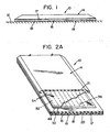
- Figure 1 depicts a device for inhibiting atmospheric ice accumulation on aircraft structure according to the invention;
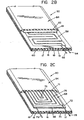
- Figures 2A depicts a pneumatic deicer embodiment according to an aspect of the invention;
- Figure 2B depicts an electrothermal embodiment according to an aspect of the invention;
- Figure 2C depicts an electromechanical embodiment according to an aspect of the invention; and
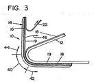
- Figure 3 depicts a method of installing a deicer according to an aspect of the invention.
- Various embodiments of the invention are depicted in Figures 1-3, wherein like numerals are employed to designate like or corresponding parts. Referring to Figure 1, a
device 10 according to an aspect of the invention for inhibiting atmospheric ice accumulation on anaircraft structure 12 comprises adeicer 14, a pressure sensitive adhesive (PSA)layer 16 for bonding thedeicer 14 to theaircraft structure 12, afirst primer layer 17 between thedeicer 14 and thePSA layer 16, and asecond primer layer 18 between the PSA layer and theaircraft structure 12. The pressure sensitiveadhesive layer 16 defines abonding surface 19 that bonds to theaircraft structure 12. Theaircraft structure 12 may be constructed from a metal, such as aluminum, or a fiber reinforced plastic. As previously described, prior rubber based adhesives used to bond deicers utilize solvents such as toluene and methyl-ethyl-ketone (MEK), and eliminating or minimizing the use of such solvents is environmentally desirable. As used herein, "pressure sensitive adhesive" means an adhesive that bonds to a surface upon application of pressure without the use of solvents to apply or activate the adhesive, and includes one or two-sided adhesive transfer tape. Various examples of suitable adhesives are provided in the following description. The pressure sensitiveadhesive layer 16 eliminates the need for rubber and solvent based adhesives. In addition, the pressure sensitive adhesive facilitates installing thedeicer 10 in the field. - Referring now to Figure 2A, a more detailed view of the
device 10 anddeicer 14 is presented with sections broken away. In this embodiment, thedeicer 14 comprises a pneumatic deicer. Pneumatic deicers have inflatable passages that are inflated causing the surface to distort and break an accreted ice cap into pieces where it is swept away by a surrounding airflow. Pneumatic deicers are very well known in the art. Two variations are generally recognized. One variation, a "sewn-type" pneumatic deicer, is depicted in Figure 2A. Anextensible fabric layer 48 is disposed over anadjacent fabric layer 50. Thefabric layers inflatable passages 52. Theindividual stitches 54 are represented schematically in Figure 2A. Thesewn fabric layers side layer 21 and an elastomeric bond-side layer 20. The breeze-side layer 21 is exposed to atmospheric icing during flight in atmospheric icing conditions. Pressurized air is periodically supplied to theinflatable passages 52 through anair connection 56, which causes the breeze-side layer 21 to distend and fracture accumulated ice. The individual tubes may run parallel to either the chordwise or spanwise directions of an airfoil section. An example of a sewn-type deicer having tubes running in both the spanwise and chordwise directions is provided in United States Patent 4,494,715 to Weisend, Jr., hereby fully incorporated herein by reference. - The second variation, a "tube-type" pneumatic deicer (not shown), may also be used in the practice of the invention. According to the tube-type deicer, the individual inflatable passages are defined by strips of extensible fabric that are rolled across the width of each strip forming a seam along the length of the tube. The tubes (substituted for
fabric layers layers - The deicer may take many forms in the practice of the invention. Referring to Figure 2B, a
device 80 according to another aspect of the invention comprises adeicer 84 bonded to the pressure sensitiveadhesive layer 16 which is bonded to the aircraft structure. In this embodiment, thedeicer 84 comprises anelectrothermal heating element 58.Heating element 58 is usually bonded to acarrier layer 62. In the embodiment presented,element 58 comprises a sheet metal ribbon disposed in a serpentine-like configuration oncarrier layer 62. As is known in the art,element 58 may be etched on thecarrier layer 62 using a photographic process. Theelement 58 andcarrier layer 62 are sandwiched between a bond-side layer 60 and a breeze-side layer 61. The breeze-side layer 61 is exposed to atmospheric icing during flight in atmospheric icing conditions. An electrical potential is applied across power leads 64 and 66 that are attached toelement 58. The potential develops a current inelement 58 which acts as an electrical resistor and generates heat. The heat conducts through the breeze-side layer and melts accumulated ice. Electrothermal deicers and anti-icers that utilize such heating elements are very well known in the art. The bond-side layer 60, breeze-side layer 61, andcarrier layer 62 are preferably formed from polymeric material which may or may not be fiber reinforced. Examples of suitable polymeric materials include chloroprene elastomer, nitrile-phenolic plastic, and polyurethane elastomer. Examples of suitable fiber reinforcements include polyester, carbon or graphite, and polyamide (Nylon or Kevlar) fibers, as well as natural fibers such as cotton. A propeller deicer having a ribbon element that may be used in the practice of the invention is described in United States Patent 4,386,749 to Sweet et al., hereby fully incorporated herein by reference. Other types of heating elements known in the art, including wire elements and conductive layers, may also be used in the practice of the invention. The opposite currents generate opposing electromagnetic fields which causes the two coils to forcefully repel each other. This type of arrangement is generally known in the art as an "electro-repulsive deicer." Examples of electro-repulsive deicers that may be used in the practice of the invention are presented in the '480 patent. An alternative embodiment of an electro-repulsive deicer that may be used in the practice of the invention is presented in United States Patent 4,875,644 to Adams et al. Other devices known in the art similar to those discussed in relation to Figures 2A through 2C may also be used in the practice of the invention. It is not intended to limit the invention to the specific embodiments presented since the invention may be used with any type of deicer. - Referring again to Figure 1, the thickness of
PSA layer 16 is preferably within the range from about 0.002 inch to about 0.045 inch, with a thickness of about 0.010 inch being most preferred. The thickness ofprimary layers deicer 14 and theaircraft structure 12 when tested according to ASTM D 1676-93 "Standard Test Method for Peel Resistance of Adhesives (T-peel Test)" with one inch by six inch samples having a one inch unbonded area at one end in order to provide a starting point for the peel. The primer layers 17, 18 and pressuresensitive adhesive 16 are chosen to obtain the desired peel strength. - A suitable pressure sensitive adhesive may be selected from the group consisting of acrylic pressure sensitive adhesive and rubber based pressure sensitive adhesive. These adhesives share a common property in having suitable bond strengths and environmental resistance. The pressure sensitive
adhesive layer 16 may include a support film, such as polypropylene or polyester support film. Suitable acrylic pressure sensitive adhesives include catalogue number F-9473PC available from the Minnesota Mining and Manufacturing Company, St. Paul, Minnesota, U.S.A.; catalogue number FasTape 1165 UHA available from Avery Denison, Painesville, Ohio, U.S.A.. Suitable rubber based pressure sensitive adhesives include catalogue number IB-1200 available from the Morgan Adhesives Company, Stow, Ohio, U.S.A., and catalogue number ARclad□ S-6450 available from Adhesives Research, Inc. Other pressure sensitive adhesives having similar properties may also be used in the practice of the invention. - The primer layers 17, 18 are utilized to provide an enhanced adhesive bond between the
PSA layer 16 and thedeicer 14 and thePSA layer 16 and theaircraft structure 12. The preferred primer for the present invention isTAPE PRIMER 94 available from 3M, which contains cyclohexane, xylene, ethyl alcohol, ethyl benzene, ethyl acetate, acrylic polymer and chlorinated polyethylene. - Referring now to Figure 3, a method of installing a device 10 (Figure 2B) according to an aspect of the invention is presented. The
device 10 is preferably provided with the pressure sensitiveadhesive layer 16 already bonded to thedeicer 14, and with arelease layer 22 bonded to thebonding surface 19 of pressure sensitiveadhesive layer 16. According to a preferred method, thedeicer 14 is prepared for application of the pressure sensitiveadhesive layer 16 in the following manner. The bottom surface of the deicer is first scrubbed with a solvent (e.g. toluene or MEK) soaked cloth. Then the surface is wiped with a cloth soaked in ethyl alcohol. Then the surface is brush coated with theprimer layer 17 and allowed to dry for approximately 5 minutes. Lastly, the pressure sensitive adhesive is applied to the deicer. - The deicer can be stored for use with the PSA installed so long as the
release layer 22 is provided onbonding surface 19 of the PSA. Therelease layer 22 is removed immediately before bonding thebonding surface 19 to theaircraft structure 12. According to a preferred method of deicer installation, the aircraft surface is preferably prepared for deicer installation by first scrubbing the surface clean with a cloth soaked in a solvent, such as toluene or MEK, and then wiping the surface with another solvent, such as ethyl alcohol. Theprimer layer 18 is then applied to the aircraft surface and allowed to air dry for approximately 5 minutes. Thedevice 10 is bonded to theaircraft structure 12 by first pressing a selectedarea 40 of the bonding surface 19 (pressure sensitive adhesive) against theaircraft structure 12 and subsequently pressing thebonding surface 19 against theaircraft structure 12 with increasing distance from the selectedarea 40. In such manner, thebonding surface 19 is first bonded to theaircraft structure 12 in the selectedarea 40. In the example presented, one side of thedeicer 14 has already been pressed against theaircraft structure 12 with increasing distance from the selectedarea 40 in the direction of arrow 42. The other side of the deicer will be forced against theaircraft structure 12 in the direction ofarrow 46 as thedeicer 14 is pressed against theaircraft structure 12 with increasing distance from selectedarea 40 in the direction ofarrow 44. In such manner, thebonding surface 19 is bonded to theaircraft structure 12 merely by applying pressure. The selectedarea 40 is preferably located near an area of maximum curvature, such as a leading edge, in order to facilitate installation. A rubber roller is preferably used to press thedeicer 14 against theaircraft structure 12. Preferably, the center of the deicer is bonded first, with the two sides following. - Application of the primer layers in the present invention causes the "wetting out" of the pressure sensitive adhesive against the bonding surfaces, and therefore provides a stronger bond. What is meant by wetting out is that the primer provides an interface between the PSA and the bonding surfaces which increases the adhesion surface area by filling in areas where the two surfaces would not otherwise come into contact due to surface abnormalities or discontinuities. The combination of materials present in the primer cause the neoprene to swell and soften. The resin in the primer is then able to act as a tie-in between the neoprene and PSA and behave similarly to a crosslinking agent between the two substrates.
- It is to be noted that although the present invention provides good deicer adhesion, it is preferred that an edge sealer be utilized around the edges of the deicer. Edge sealers are typically applied to the perimeter of deicers in order to seal the pressure sensitive
adhesive layer 16 against fluid penetration during service on the aircraft. Penetration of various fluids such as oil, hydraulic fluid, aircraft fuel, and deicing fluids may degrade the adhesive interface and lead to premature failure. Edge sealers known for use with prior aircraft deicers find equal utility in the practice of the invention. Examples of such materials include polysulfide fuel tank sealants, polysulfide windshield sealants, polysulfide fairing compounds, fluorelastomer (Viton) sealants, chloroprene sealants, epoxy sealants and adhesives, and urethane sealants and adhesives. The preferred edge sealer is PR-1422 Class B available from Courtaulds Aerospace. PR-1422 Class B is a two-part, polysulfide, liquid polymer compound. - As used herein, the term "flexible" refers to the ability of the
deicer 14 to conform to the shape of theaircraft structure 12. More particularly, "flexible" means that thedeicer 14 can conform to the shape of theaircraft structure 12 with reasonable force and without damage to thedeicer 14. Most deicers having a predominantly elastomeric construction inherently have the necessary flexibility. - Further aspects of the invention are demonstrated by the following examples.
- Samples according to an aspect of the invention were prepared as follows. Adhesion samples were prepared by scrubbing the bottom surface thereof with a toluene soaked cloth. Then the surface was wiped with a cloth soaked in ethyl alcohol. Then the surface was brush coated with a primer and allowed to dry for approximately 5 minutes. The F-9473PC pressure sensitive adhesive was applied to the primed sample. The release layer from the PSA was then removed and the samples were pressed to either aluminum or neoprene substrates. The substrates were prepared by first scrubbing the surface clean with a cloth soaked with toluene, and then wiping the surface with cloth soaked with ethyl alcohol. The same primer was then applied to the substrates and allowed to air dry for approximately 5 minutes. Different samples were allowed to dry for 4, 24 and 168 hours and subjected to a 180° T-peel adhesion test between the rubber/fabric layer and the substrate. The peel tests were conducted according to ASTM D 1676-93 "Standard Test Method for Peel Resistance of Adhesives (T-peel Test)" with one inch by six inch samples having a one inch unbonded area at one end in order to provide a starting point for the peel. Average peel strength of each set of four samples at the corresponding dry time is presented in Table 1. The force necessary to separate the samples in a peel failure mode begins with an initially greater force that subsequently drops to a steady lesser force. The steady removal force is indicated as "Peel Strength" (piw = pounds per inch of sample width)

- The F-9473PC adhesive was applied as follows: apply to the sample on the adhesive side by pressing it against the sample with a rubber roller. Then remove the release layer from the pressure sensitive adhesive and immediately press the sample against the substrate with a rubber roller. Average peel data for each set of two samples at the dry times is presented in Table 1.
- Samples not in accordance with the invention were prepared as follows. Adhesion samples were prepared by scrubbing the bottom surface thereof with a toluene soaked cloth. Then the surface was wiped with a cloth soaked in ethyl alcohol. Then the F-9473PC pressure sensitive adhesive was applied to the sample. The release layer from the PSA was then removed and the samples were pressed to either aluminum or neoprene substrates. The substrates were prepared by first scrubbing the surface clean with a cloth soaked with toluene, and then wiping the surface with cloth soaked with ethyl alcohol. Different samples were allowed to dry for 4, 24 and 168 hours and subjected to the adhesion test in Example 1.

- The F-9473PC adhesive was applied as follows: apply to the sample on the adhesive side by pressing it against the sample with a rubber roller. Then remove the release layer from the pressure sensitive adhesive and immediately press the sample against the substrate with a rubber roller. Average peel data for each set of two samples at the dry times is presented in Table 1.

- This data demonstrates that the Example 1 samples provide unexpectedly much better adhesion in comparison to the Example 2 samples.
- In addition, it has been found that the present invention provides for a deicer with a much smoother or consistent profile than a deicer adhered according to the prior art method using 1300L. The installation technique necessary for application of and conditioning of 1300L renders a very non-uniform thickness 1300L layer. The PSA of the present invention, however, has a consistent thickness throughout which therefore provides for a smooth aerodynamic profile.
- Also, the present invention requires the use of solvents in the field only for cleaning the aircraft surface, thereby drastically reducing the amount of solvents that were previously necessary to install a deicer.
- Another advantage of the present invention is ease of installation and the reduction in installation time. A typical installation previously took on the order of 3 hours with a dry time of 8 hours under optimum conditions but typically 24 to 48 hours for the 1300L adhesive for a total of eleven hours. A typical installation according to the present invention takes on the order of 45 minutes with a dry time of 1 hour for the PSA. Obviously, the present invention provides a much more desirable deicer replacement down time for the aircraft.
- It is evident that many variations are possible without departing from the scope of the invention as defined by the claims that follow.
Claims (15)
- A device (10) for inhibiting atmospheric ice accumulation on an aircraft structure (12), comprising:a deicer (14);a pressure sensitive adhesive layer (16) bonded to the deicer (14);characterised by,a primer layer (18) applied to the aircraft structure (12); and whereinthe pressure sensitive adhesive layer (16) defines a bonding surface (19) that is bound to the primer layer (18).
- The device of claim 1, wherein the pressure sensitive adhesive layer (16) comprises an adhesive selected from the group consisting of acrylic pressure sensitive adhesive and rubber based pressure sensitive adhesive.
- The device of claim 1, wherein the deicer (14) comprises an elastomeric layer (20,60).
- The device of claim 1, wherein the deicer (14), comprises a polymeric layer (60).
- The device of claim 1, wherein the deicer (14) comprises a pneumatic deicer.
- The device of claim 1, wherein the deicer (14) comprises an electrothermal heating element (58).
- The device of claim 1, wherein the deicer (14) comprises an electromechanical deicer.
- The device of claim 1, comprising a further primer layer (17) applied between the deicer (14) and the pressure sensitive adhesive layer (16).
- A method for attaching a deicer (14) to an aircraft structure (12), characterised by the steps of:applying a primer layer (18) to the aircraft structure (12); andbonding the deicer (14) to the primer layer (18) by means of a pressure sensitive adhesive layer (16).
- The method of claim 9, comprising the step of applying a further primer layer (17) to the deicer and bonding the pressure sensitive adhesive layer (16) to the further primer layer (17).
- The method of claim 9, further comprising the step of first pressing a selected area of the pressure sensitive adhesive layer (16) against the primer layer (18) and subsequently pressing the pressure sensitive adhesive layer (16) against the primer layer (18) with increasing distance from the selected area.
- The method of claim 9, further comprising the step of cleaning the aircraft structure (12) with a solvent.
- The method of claim 9, further comprising the step of cleaning the deicer (14) with a solvent.
- The method of claim 9, wherein the pressure sensitive adhesive layer (16) is selected from the group consisting of acrylic pressure sensitive adhesive and rubber based pressure sensitive adhesive.
- The method of claim 9, wherein the pressure sensitive adhesive layer (16) comprises acrylic pressure sensitive adhesive.
Applications Claiming Priority (2)
| Application Number | Priority Date | Filing Date | Title |
|---|---|---|---|
| US09/136,810 US6250587B1 (en) | 1998-08-19 | 1998-08-19 | Pressure sensitive adhesive for mounting a deicer and method for mounting thereof |
| US136810 | 1998-08-19 |
Publications (2)
| Publication Number | Publication Date |
|---|---|
| EP0980827A1 EP0980827A1 (en) | 2000-02-23 |
| EP0980827B1 true EP0980827B1 (en) | 2006-03-22 |
Family
ID=22474470
Family Applications (1)
| Application Number | Title | Priority Date | Filing Date |
|---|---|---|---|
| EP99306414A Expired - Lifetime EP0980827B1 (en) | 1998-08-19 | 1999-08-13 | Pressure sensitive adhesive for mounting a deicer and method for mounting thereof |
Country Status (4)
| Country | Link |
|---|---|
| US (1) | US6250587B1 (en) |
| EP (1) | EP0980827B1 (en) |
| CA (1) | CA2279612C (en) |
| DE (1) | DE69930479T2 (en) |
Cited By (1)
| Publication number | Priority date | Publication date | Assignee | Title |
|---|---|---|---|---|
| US9487823B2 (en) | 2002-12-20 | 2016-11-08 | Qiagen Gmbh | Nucleic acid amplification |
Families Citing this family (9)
| Publication number | Priority date | Publication date | Assignee | Title |
|---|---|---|---|---|
| US7178760B2 (en) * | 2003-05-30 | 2007-02-20 | Bombardier Aéronautique | Method and apparatus for inhibiting accretion of airborne material on a surface of an aircraft |
| US8353995B2 (en) * | 2005-07-15 | 2013-01-15 | 3M Innovative Properties Company | Automobile panel repair laminate |
| EP1762627A1 (en) | 2005-09-09 | 2007-03-14 | Qiagen GmbH | Method for the activation of a nucleic acid for performing a polymerase reaction |
| US7869181B2 (en) * | 2006-03-29 | 2011-01-11 | The Boeing Company | Flex circuit lightning protection applique system for skin fasteners in composite structures |
| GB2438389A (en) * | 2006-05-23 | 2007-11-28 | Gkn Aerospace Transparency Sys | Heating system for leading edge of aircraft |
| FR2935357B1 (en) * | 2008-09-03 | 2010-08-27 | Aircelle Sa | METHOD FOR MANUFACTURING A NACELLE ELEMENT |
| WO2012080830A2 (en) | 2010-12-17 | 2012-06-21 | Aerazur S.A. | Aircraft de-icer systems and methods |
| US10703492B2 (en) * | 2018-01-16 | 2020-07-07 | Goodrich Corporation | Adhesive lay-up and method for attaching pneumatic de-icers |
| US20200115593A1 (en) | 2018-10-11 | 2020-04-16 | Goodrich Corporation | Thermally switchable high shear pressure sensitive adhesive |
Family Cites Families (11)
| Publication number | Priority date | Publication date | Assignee | Title |
|---|---|---|---|---|
| US3092250A (en) * | 1963-06-04 | Pressure sensitive adhesive tape in which the adhesive | ||
| US2762897A (en) * | 1951-06-28 | 1956-09-11 | Lockheed Aircraft Corp | De-icing means for aircraft and the like |
| US2757273A (en) * | 1952-12-12 | 1956-07-31 | Goodyear Tire & Rubber | De-icer |
| US2957662A (en) * | 1956-02-17 | 1960-10-25 | Goodrich Co B F | Inflatable ice-removable apparatus for aircraft |
| US2889038A (en) * | 1956-07-05 | 1959-06-02 | Minnesota Mining & Mfg | Double-coated pressure-sensitive adhesive tape |
| US3604666A (en) | 1969-08-25 | 1971-09-14 | Goodrich Co B F | Pneumatic deicer |
| CA1069870A (en) | 1977-03-04 | 1980-01-15 | B.F. Goodrich Company (The) | Propeller deicer |
| US4494715A (en) * | 1983-05-09 | 1985-01-22 | The B. F. Goodrich Company | Deicer |
| US4875644A (en) * | 1988-10-14 | 1989-10-24 | The B. F. Goodrich Company | Electro-repulsive separation system for deicing |
| JP3501417B2 (en) * | 1994-09-26 | 2004-03-02 | 株式会社ブリヂストン | Information display method for rubber vulcanized molded products |
| US6352601B1 (en) | 1994-12-27 | 2002-03-05 | The B. F. Goodrich Company | Self-adhering ice protector |
-
1998
- 1998-08-19 US US09/136,810 patent/US6250587B1/en not_active Expired - Lifetime
-
1999
- 1999-08-04 CA CA002279612A patent/CA2279612C/en not_active Expired - Lifetime
- 1999-08-13 EP EP99306414A patent/EP0980827B1/en not_active Expired - Lifetime
- 1999-08-13 DE DE69930479T patent/DE69930479T2/en not_active Expired - Lifetime
Cited By (1)
| Publication number | Priority date | Publication date | Assignee | Title |
|---|---|---|---|---|
| US9487823B2 (en) | 2002-12-20 | 2016-11-08 | Qiagen Gmbh | Nucleic acid amplification |
Also Published As
| Publication number | Publication date |
|---|---|
| CA2279612A1 (en) | 2000-02-19 |
| DE69930479D1 (en) | 2006-05-11 |
| EP0980827A1 (en) | 2000-02-23 |
| CA2279612C (en) | 2007-11-13 |
| DE69930479T2 (en) | 2006-12-07 |
| US6250587B1 (en) | 2001-06-26 |
Similar Documents
| Publication | Publication Date | Title |
|---|---|---|
| EP0720946B1 (en) | self-adhering ice protector | |
| EP0980827B1 (en) | Pressure sensitive adhesive for mounting a deicer and method for mounting thereof | |
| US5427332A (en) | Modular ice protection assembly | |
| US5865397A (en) | Method and apparatus for creating detail surfaces on composite aircraft structures | |
| JP5089592B2 (en) | Copper grid restoration technology for lightning protection | |
| EP0604751A1 (en) | Compressible nose dynamic deicer | |
| EP0471923B1 (en) | A repair patch and method for effecting repair to damaged, non-stressed aircraft structure | |
| US5609314A (en) | Skin for a deicer | |
| EP0604752B1 (en) | Improved skin for a deicer | |
| EP0855340A2 (en) | Hybrid deicer with element sequence control | |
| JPH03208797A (en) | Monolithic structural wing incorporating enection system | |
| US4833029A (en) | Honeycomb facesheet material and honeycomb made therewith | |
| US6520452B1 (en) | Deicer for aircraft | |
| US5743494A (en) | Polyurethane deicer | |
| CA2382958C (en) | A method of producing a joint | |
| US5449134A (en) | Apparatus and method for providing a pneumatic de-icer with a replaceable environment resistant surface | |
| WO1981000993A1 (en) | Composite leading edge for aircraft | |
| EP4253012A1 (en) | Laser welded pneumatic deicer boots for aircraft | |
| US7064302B2 (en) | Electrical connection for a resistor element made of electrically-conductive fibers | |
| JPH1077464A (en) | Gasket includingreinforced layer | |
| EP1903182A2 (en) | Rebonding a metallized fabric to an underlying layer | |
| EP4056657B1 (en) | Ice protection coating and bonding methods thereof | |
| EP0872417A1 (en) | Hybrid deicer | |
| US20040217110A1 (en) | Heating blanket and methods for curing composites | |
| EP3674077B1 (en) | Composite structures with discontinous bond lines |
Legal Events
| Date | Code | Title | Description |
|---|---|---|---|
| PUAI | Public reference made under article 153(3) epc to a published international application that has entered the european phase |
Free format text: ORIGINAL CODE: 0009012 |
|
| AK | Designated contracting states |
Kind code of ref document: A1 Designated state(s): DE FR GB |
|
| AX | Request for extension of the european patent |
Free format text: AL;LT;LV;MK;RO;SI |
|
| 17P | Request for examination filed |
Effective date: 20000725 |
|
| AKX | Designation fees paid |
Free format text: DE FR GB |
|
| RAP1 | Party data changed (applicant data changed or rights of an application transferred) |
Owner name: GOODRICH CORPORATION |
|
| 17Q | First examination report despatched |
Effective date: 20030319 |
|
| GRAP | Despatch of communication of intention to grant a patent |
Free format text: ORIGINAL CODE: EPIDOSNIGR1 |
|
| GRAS | Grant fee paid |
Free format text: ORIGINAL CODE: EPIDOSNIGR3 |
|
| GRAA | (expected) grant |
Free format text: ORIGINAL CODE: 0009210 |
|
| AK | Designated contracting states |
Kind code of ref document: B1 Designated state(s): DE FR GB |
|
| REG | Reference to a national code |
Ref country code: GB Ref legal event code: FG4D |
|
| REF | Corresponds to: |
Ref document number: 69930479 Country of ref document: DE Date of ref document: 20060511 Kind code of ref document: P |
|
| ET | Fr: translation filed | ||
| PLBE | No opposition filed within time limit |
Free format text: ORIGINAL CODE: 0009261 |
|
| STAA | Information on the status of an ep patent application or granted ep patent |
Free format text: STATUS: NO OPPOSITION FILED WITHIN TIME LIMIT |
|
| 26N | No opposition filed |
Effective date: 20061227 |
|
| REG | Reference to a national code |
Ref country code: FR Ref legal event code: PLFP Year of fee payment: 18 |
|
| REG | Reference to a national code |
Ref country code: FR Ref legal event code: PLFP Year of fee payment: 19 |
|
| REG | Reference to a national code |
Ref country code: FR Ref legal event code: PLFP Year of fee payment: 20 |
|
| PGFP | Annual fee paid to national office [announced via postgrant information from national office to epo] |
Ref country code: DE Payment date: 20180719 Year of fee payment: 20 Ref country code: FR Payment date: 20180720 Year of fee payment: 20 |
|
| PGFP | Annual fee paid to national office [announced via postgrant information from national office to epo] |
Ref country code: GB Payment date: 20180720 Year of fee payment: 20 |
|
| REG | Reference to a national code |
Ref country code: DE Ref legal event code: R071 Ref document number: 69930479 Country of ref document: DE |
|
| REG | Reference to a national code |
Ref country code: GB Ref legal event code: PE20 Expiry date: 20190812 |
|
| PG25 | Lapsed in a contracting state [announced via postgrant information from national office to epo] |
Ref country code: GB Free format text: LAPSE BECAUSE OF EXPIRATION OF PROTECTION Effective date: 20190812 |