EP0980667A2 - A mop - Google Patents
A mop Download PDFInfo
- Publication number
- EP0980667A2 EP0980667A2 EP99305846A EP99305846A EP0980667A2 EP 0980667 A2 EP0980667 A2 EP 0980667A2 EP 99305846 A EP99305846 A EP 99305846A EP 99305846 A EP99305846 A EP 99305846A EP 0980667 A2 EP0980667 A2 EP 0980667A2
- Authority
- EP
- European Patent Office
- Prior art keywords
- handle
- cleaning head
- cleaning
- mop
- flaps
- Prior art date
- Legal status (The legal status is an assumption and is not a legal conclusion. Google has not performed a legal analysis and makes no representation as to the accuracy of the status listed.)
- Withdrawn
Links
Images


Classifications
-
- A—HUMAN NECESSITIES
- A47—FURNITURE; DOMESTIC ARTICLES OR APPLIANCES; COFFEE MILLS; SPICE MILLS; SUCTION CLEANERS IN GENERAL
- A47L—DOMESTIC WASHING OR CLEANING; SUCTION CLEANERS IN GENERAL
- A47L13/00—Implements for cleaning floors, carpets, furniture, walls, or wall coverings
- A47L13/10—Scrubbing; Scouring; Cleaning; Polishing
- A47L13/20—Mops
- A47L13/24—Frames for mops; Mop heads
- A47L13/254—Plate frames
- A47L13/258—Plate frames of adjustable or foldable type
-
- A—HUMAN NECESSITIES
- A47—FURNITURE; DOMESTIC ARTICLES OR APPLIANCES; COFFEE MILLS; SPICE MILLS; SUCTION CLEANERS IN GENERAL
- A47L—DOMESTIC WASHING OR CLEANING; SUCTION CLEANERS IN GENERAL
- A47L13/00—Implements for cleaning floors, carpets, furniture, walls, or wall coverings
- A47L13/10—Scrubbing; Scouring; Cleaning; Polishing
- A47L13/14—Scrubbing; Scouring; Cleaning; Polishing combined with squeezing or wringing devices
- A47L13/146—Scrubbing; Scouring; Cleaning; Polishing combined with squeezing or wringing devices having pivoting squeezing plates
-
- A—HUMAN NECESSITIES
- A47—FURNITURE; DOMESTIC ARTICLES OR APPLIANCES; COFFEE MILLS; SPICE MILLS; SUCTION CLEANERS IN GENERAL
- A47L—DOMESTIC WASHING OR CLEANING; SUCTION CLEANERS IN GENERAL
- A47L13/00—Implements for cleaning floors, carpets, furniture, walls, or wall coverings
- A47L13/10—Scrubbing; Scouring; Cleaning; Polishing
- A47L13/20—Mops
- A47L13/24—Frames for mops; Mop heads
Definitions
- This invention relates to a mop for cleaning floors and other surfaces.
- Floor mops are well known.
- One such mop comprises an elongate handle having a head attached to a lower end thereof.
- a cleaning head typically of absorbent sponge or foamed plastics material is attached to the underside of the head.
- the most convenient way of using a mop is for the user to hold the handle at an angle of about 40° to the floor and move the cleaning head to-and-fro by alternately pushing and pulling the handle. Accordingly, it is common for the cleaning head to incline at an angle of about 40° relative to the axis of the handle, so that the entire cleaning head can remain in contact with the floor when the mop is used.
- the cleaning head of such a mop is also typically arranged so that the longitudinal axis of the cleaning head extends perpendicular to the normal to-and-fro motions of the head, so that a wide area of floor can be cleaned by each movement.
- a disadvantage of the above-mentioned arrangement is that the head of the mop is often too wide to fit into confined spaces, say between cupboards and appliances. It is possible to reach into such spaces by turning the mop through 90°, so that the longitudinal axis of the cleaning head extends longitudinally of the space.
- a disadvantage of this is that the head of the mop will be inclined to one side making the mop difficult to use. Moreover, only an edge of the cleaning head will be in contact with the floor, unless there is sufficient room in the confined space to incline the handle to one side.
- a mop comprising an elongate handle and a cleaning head disposed at a distal end of the handle, the cleaning head being adapted to support a cleaning member, which cleaning member provides a cleaning surface arranged to lie substantially in a plane at an inclined angle relative to the axis of the handle, the cleaning head being rotatably mounted to the handle, such that the cleaning surface can be rotated within the plane.
- the inclined angle at which the cleaning head is mounted is typically from 10 to 80° relative to the axis of the handle.
- the cleaning head can be rotated, so that the longitudinal axis of its cleaning surface can be orientated at an appropriate direction within the inclined plane. Accordingly, in normal use, the cleaning head is preferably arranged so that the longitudinal axis of its cleaning surface extends substantially perpendicularly to the direction of a typical to-and-fro cleaning motion when the mop is in use.
- the cleaning head is arranged to be turned or rotated, say through 90°, so that the longitudinal axis of the cleaning surface can extend in line with the to-and-fro cleaning motion mentioned above.
- the mop includes means for locking the cleaning head within the plane at a plurality of predetermined positions of rotation, the positions of rotation preferably being disposed at 90° to each other.
- the cleaning head preferably comprises a pair of hinged flaps which support the cleaning member, and actuator means being provided for hinging the flaps together, such that the cleaning member is permitted to fold transverse to the longitudinal axis of the cleaning surface.
- opposed portions of the cleaning member can be urged together (into face to face contact)when the flaps are hinged, so that surplus liquid may be expelled from the cleaning member.
- the actuator means preferably comprises a slidable member, which is slidable axially of the elongate handle from a position proximal to an operator to a distal position.
- the cleaning head is preferably rotatably mounted to the slidable member.
- the locking means is disposed between the slidable member and the cleaning head.
- the slidable member is preferably angled by the angle of 10 to 80°, the cleaning head being rotatable about an axis which extends axially of the angled distal or lower portion of the slidable member.
- the slidable member comprises an elongate sleeve or tube slidably mounted on the handle, a distal or lower end of the tube being arranged to be orientated at the inclined angle of about 10 to 80°.
- the cleaning surface has a plane substantially perpendicular to the axis of rotation of the cleaning head.
- the handle comprises a flexible extension, which extends through the inclined angle portion of the elongate tube and which is connected at its distal or lower end to respective actuator portions on the flaps.
- the flaps of the cleaning head are hinged by relative axial movement between the handle and the elongate sleeve or tube, to which the cleaning head is mounted.
- a mop comprising an elongate handle which includes a flexible extension and a cleaning head disposed at a distal end of the handle, the cleaning head comprising a pair of hinged flaps which support a cleaning member, the cleaning head being at an inclined angle relative to the longitudinal axis of the handle through an angled neck portion, and actuator means provided for hinging the flaps together, the flexible extension extending through the angled neck portion so as to permit actuation of the flaps.
- a floor mop comprising an elongate handle 10, a tubular (hand grippable) sleeve 11 slidably mounted to the lower or distal end of the handle 10 and a cleaning head 12 rotatably mounted to the lower end of the tubular sleeve 11.
- the cleaning head 12 is provided on its underside with a cleaning pad 13 of sponge or foamed plastics material.
- the underside of the cleaning pad 13 is substantially flat and generally lies in a plane, which extends substantially perpendicularly to the axis of rotation of the cleaning head 12.
- the sleeve 11 has a portion lla at an angle of about 40° at its lower end and the axis of rotation of the cleaning head 12 is disposed at a corresponding angle to the longitudinal axis of the handle 10.
- the cleaning head 12 is substantially rectangular in shape, with a central portion 14 which is rotatably mounted to the sleeve 11. Opposite ends of the cleaning head 12 have flaps 15, which carry respective portions of the cleaning pad 13.
- the flaps 15 are hinged adjacent their inner ends to the central portion 14 of the cleaning head, such that they can pivot about respective pivot lines P1 and P2, which extend transverse the longitudinal axis of the cleaning head 12.
- the lower end of the handle 10 extends inside the tubular sleeve 11.
- the handle 10 is rotatably coupled at its lower end to a flexible coupling element 16, which extends axially of the sleeve 11.
- the lower end of the coupling element 16 is rotatably coupled to an actuator 17, which is slidably mounted within the central portion 14 of the cleaning head 12, along a line which extends along the axis of rotation of the cleaning head 12.
- the actuator 17 engages with respective inward portions of the flaps 15.
- the flaps 15 can be moved between their position of Figure 3, in which they are coplanar and the folded position of Figure 4, by moving the handle 10 axially upwardly relative to the sleeve 11, thereby pulling the coupling element 16 and actuator 17 upwardly: this in turn pulls on the inner end of the flaps 15, so they can pivot together.
- the cleaning head 12 is normally arranged as shown in Figure 1, such that the longitudinal axis of the cleaning head 12 lies perpendicular to the normal to-and-fro direction of movement of the mop.
- the handle 10 is angled rearwardly and thus the undersurface of the cleaning pad 13 can be kept in contact with the floor, whilst the user stands behind the mop in operation.
- the cleaning head 12 can be rotated through 90°, once it has been unlocked from the sleeve 11, by pressing on a button 19 disposed at the front of sleeve 11.
- the longitudinal axis of the head 12 now extends in line with the normal direction of movement.
- the handle 10 remains angled rearwardly and the entire undersurface of the pad 13 remains in contact with the floor.
- the mop enables easy and efficient cleaning in confined spaces.
- Excess liquid can be squeezed from the pad 13 and/or new cleaning liquid can be absorbed by relative movement between the handle 10 and the sleeve 11, to cause the flaps 15 to fold together, as shown in Figure 4.
- the flaps 15 can be folded together, regardless of the direction of rotary orientation of the cleaning head 12.
- the flaps 15 fold about lines, which extend transverse the longitudinal axis of the head 12 and thus the head can easily fit with a bucket of a relatively small diameter.
Abstract
Description
- This invention relates to a mop for cleaning floors and other surfaces.
- Floor mops are well known. One such mop comprises an elongate handle having a head attached to a lower end thereof. A cleaning head typically of absorbent sponge or foamed plastics material is attached to the underside of the head.
- Typically, the most convenient way of using a mop is for the user to hold the handle at an angle of about 40° to the floor and move the cleaning head to-and-fro by alternately pushing and pulling the handle. Accordingly, it is common for the cleaning head to incline at an angle of about 40° relative to the axis of the handle, so that the entire cleaning head can remain in contact with the floor when the mop is used.
- The cleaning head of such a mop is also typically arranged so that the longitudinal axis of the cleaning head extends perpendicular to the normal to-and-fro motions of the head, so that a wide area of floor can be cleaned by each movement.
- A disadvantage of the above-mentioned arrangement is that the head of the mop is often too wide to fit into confined spaces, say between cupboards and appliances. It is possible to reach into such spaces by turning the mop through 90°, so that the longitudinal axis of the cleaning head extends longitudinally of the space. However, a disadvantage of this is that the head of the mop will be inclined to one side making the mop difficult to use. Moreover, only an edge of the cleaning head will be in contact with the floor, unless there is sufficient room in the confined space to incline the handle to one side.
- We have now devised a mop which alleviates the above-mentioned problems.
- In accordance with this invention, there is provided a mop comprising an elongate handle and a cleaning head disposed at a distal end of the handle, the cleaning head being adapted to support a cleaning member, which cleaning member provides a cleaning surface arranged to lie substantially in a plane at an inclined angle relative to the axis of the handle, the cleaning head being rotatably mounted to the handle, such that the cleaning surface can be rotated within the plane.
- The inclined angle at which the cleaning head is mounted is typically from 10 to 80° relative to the axis of the handle.
- In use, the cleaning head can be rotated, so that the longitudinal axis of its cleaning surface can be orientated at an appropriate direction within the inclined plane. Accordingly, in normal use, the cleaning head is preferably arranged so that the longitudinal axis of its cleaning surface extends substantially perpendicularly to the direction of a typical to-and-fro cleaning motion when the mop is in use.
- In order to permit the mop to reach into confined spaces, it is preferred that the cleaning head is arranged to be turned or rotated, say through 90°, so that the longitudinal axis of the cleaning surface can extend in line with the to-and-fro cleaning motion mentioned above.
- Preferably, the mop includes means for locking the cleaning head within the plane at a plurality of predetermined positions of rotation, the positions of rotation preferably being disposed at 90° to each other.
- A disadvantage of conventional mop heads is that the head is often too wide to fit into a bucket. Thus, advantageously the cleaning head preferably comprises a pair of hinged flaps which support the cleaning member, and actuator means being provided for hinging the flaps together, such that the cleaning member is permitted to fold transverse to the longitudinal axis of the cleaning surface.
- Preferably opposed portions of the cleaning member can be urged together (into face to face contact)when the flaps are hinged, so that surplus liquid may be expelled from the cleaning member.
- The actuator means preferably comprises a slidable member, which is slidable axially of the elongate handle from a position proximal to an operator to a distal position.
- The cleaning head is preferably rotatably mounted to the slidable member. Preferably the locking means is disposed between the slidable member and the cleaning head.
- The slidable member is preferably angled by the angle of 10 to 80°, the cleaning head being rotatable about an axis which extends axially of the angled distal or lower portion of the slidable member.
- Preferably the slidable member comprises an elongate sleeve or tube slidably mounted on the handle, a distal or lower end of the tube being arranged to be orientated at the inclined angle of about 10 to 80°.
- Preferably the cleaning surface has a plane substantially perpendicular to the axis of rotation of the cleaning head.
- Preferably the handle comprises a flexible extension, which extends through the inclined angle portion of the elongate tube and which is connected at its distal or lower end to respective actuator portions on the flaps. Thus, the flaps of the cleaning head are hinged by relative axial movement between the handle and the elongate sleeve or tube, to which the cleaning head is mounted.
- According to a further aspect of the present invention, there is provided a mop comprising an elongate handle which includes a flexible extension and a cleaning head disposed at a distal end of the handle, the cleaning head comprising a pair of hinged flaps which support a cleaning member, the cleaning head being at an inclined angle relative to the longitudinal axis of the handle through an angled neck portion, and actuator means provided for hinging the flaps together, the flexible extension extending through the angled neck portion so as to permit actuation of the flaps.
- An embodiment of this invention will now be described by way of example only and with reference to the accompanying drawings, in which:
- Figure 1 is a perspective view of an exemplary floor mop in accordance with this invention;
- Figure 2 is a plan view of the lower end of the mop of Figure 1;
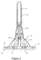
- Figure 3 is a sectional view along the line III-III of Figure 2; and
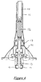
- Figure 4 is a sectional view along the line III-III of Figure 2, showing the head folded.
-
- Referring to the drawings, there is shown a floor mop comprising an
elongate handle 10, a tubular (hand grippable) sleeve 11 slidably mounted to the lower or distal end of thehandle 10 and acleaning head 12 rotatably mounted to the lower end of the tubular sleeve 11. Thecleaning head 12 is provided on its underside with acleaning pad 13 of sponge or foamed plastics material. - The underside of the
cleaning pad 13 is substantially flat and generally lies in a plane, which extends substantially perpendicularly to the axis of rotation of thecleaning head 12. The sleeve 11 has a portion lla at an angle of about 40° at its lower end and the axis of rotation of thecleaning head 12 is disposed at a corresponding angle to the longitudinal axis of thehandle 10. - Referring to Figure 2 of the drawings, the
cleaning head 12 is substantially rectangular in shape, with acentral portion 14 which is rotatably mounted to the sleeve 11. Opposite ends of thecleaning head 12 haveflaps 15, which carry respective portions of thecleaning pad 13. - Referring to Figure 3 of the drawings, the
flaps 15 are hinged adjacent their inner ends to thecentral portion 14 of the cleaning head, such that they can pivot about respective pivot lines P1 and P2, which extend transverse the longitudinal axis of thecleaning head 12. - The lower end of the
handle 10 extends inside the tubular sleeve 11. Thehandle 10 is rotatably coupled at its lower end to aflexible coupling element 16, which extends axially of the sleeve 11. The lower end of thecoupling element 16 is rotatably coupled to anactuator 17, which is slidably mounted within thecentral portion 14 of thecleaning head 12, along a line which extends along the axis of rotation of thecleaning head 12. Theactuator 17 engages with respective inward portions of theflaps 15. - Referring to Figure 4 of the drawings, the
flaps 15 can be moved between their position of Figure 3, in which they are coplanar and the folded position of Figure 4, by moving thehandle 10 axially upwardly relative to the sleeve 11, thereby pulling thecoupling element 16 andactuator 17 upwardly: this in turn pulls on the inner end of theflaps 15, so they can pivot together. - In use, the
cleaning head 12 is normally arranged as shown in Figure 1, such that the longitudinal axis of thecleaning head 12 lies perpendicular to the normal to-and-fro direction of movement of the mop. Thehandle 10 is angled rearwardly and thus the undersurface of thecleaning pad 13 can be kept in contact with the floor, whilst the user stands behind the mop in operation. - In order to clean in confined spaces, the
cleaning head 12 can be rotated through 90°, once it has been unlocked from the sleeve 11, by pressing on abutton 19 disposed at the front of sleeve 11. In this configuration, the longitudinal axis of thehead 12 now extends in line with the normal direction of movement. However, thehandle 10 remains angled rearwardly and the entire undersurface of thepad 13 remains in contact with the floor. Thus, the mop enables easy and efficient cleaning in confined spaces. - Excess liquid can be squeezed from the
pad 13 and/or new cleaning liquid can be absorbed by relative movement between thehandle 10 and the sleeve 11, to cause theflaps 15 to fold together, as shown in Figure 4. Theflaps 15 can be folded together, regardless of the direction of rotary orientation of thecleaning head 12. - The
flaps 15 fold about lines, which extend transverse the longitudinal axis of thehead 12 and thus the head can easily fit with a bucket of a relatively small diameter.
Claims (10)
- A mop comprising an elongate handle and a cleaning head disposed at a distal end of the handle, the cleaning head being adapted to support a cleaning member, which cleaning member provides a cleaning surface arranged to lie substantially in a plane at an inclined angle relative to the axis of the handle, the cleaning head being rotatably mounted to the handle, such that the cleaning surface can be rotated within the plane.
- A mop according to claim 1, characterised in that the inclined angle at which the cleaning head is mounted is in the range 10° to 80° relative to the axis of the handle.
- A mop according to claim 1 or 2, characterised in that the cleaning head is lockable at a plurality of predetermined positions of rotation within the plane (such as at 90° to each other).
- A mop according to any of claims 1 to 3, characterised in that the cleaning head preferably comprises a pair of hinged flaps which support the cleaning member, and actuator means being provided for hinging the flaps together, such that the cleaning member is permitted to fold transverse to the longitudinal axis.
- A mop according to claim 4, characterised in that the actuator means comprises a slidable member, which is slidable axially of said elongate handle.
- A mop according to claim 5, characterised in that the head is rotatably mounted to the slidable member.
- A mop according to claim 5 or 6, characterised in that the slidable member is angled by an angle of 10° to 80°, the cleaning head being rotatable about an axis which extends axially of the angled distal or lower portion of the slidable member.
- A mop according to any of claims 5 to 7, characterised in that the slidable member comprises an elongate tube slidably mounted to the handle.
- A mop according to any of claims 5 to 8, characterised in that the handle comprises a flexible extension, which extends through the inclined angle portion of the elongate tube and which is connected at its distal or lower end to respective actuator portions on the flaps.
- A mop comprising an elongate handle which includes a flexible extension and a cleaning head disposed at a distal end of the handle, the cleaning head comprising a pair of hinged flaps which support a cleaning member, the cleaning head being at an inclined angle relative to the longitudinal axis of the handle through an angled neck portion, and actuator means provided for hinging the flaps together, the flexible extension extends through the angled neck portion so as to permit actuation of the flaps.
Applications Claiming Priority (2)
| Application Number | Priority Date | Filing Date | Title |
|---|---|---|---|
| GB9816037 | 1998-07-23 | ||
| GBGB9816037.7A GB9816037D0 (en) | 1998-07-23 | 1998-07-23 | A mop |
Publications (2)
| Publication Number | Publication Date |
|---|---|
| EP0980667A2 true EP0980667A2 (en) | 2000-02-23 |
| EP0980667A3 EP0980667A3 (en) | 2002-01-02 |
Family
ID=10836030
Family Applications (1)
| Application Number | Title | Priority Date | Filing Date |
|---|---|---|---|
| EP99305846A Withdrawn EP0980667A3 (en) | 1998-07-23 | 1999-07-23 | A mop |
Country Status (2)
| Country | Link |
|---|---|
| EP (1) | EP0980667A3 (en) |
| GB (1) | GB9816037D0 (en) |
Cited By (6)
| Publication number | Priority date | Publication date | Assignee | Title |
|---|---|---|---|---|
| US7650665B2 (en) | 2006-07-18 | 2010-01-26 | Kimberly-Clark Worlwide, Inc. | Mop assembly with fastener channels |
| US7735182B2 (en) | 2006-07-18 | 2010-06-15 | Kimberly-Clark Worldwide, Inc. | Mop assembly with reversible head |
| WO2014059105A1 (en) * | 2012-10-11 | 2014-04-17 | 3M Innovative Properties Company | Foldable spin flat mop and cleaning tool including same |
| CN107468186A (en) * | 2017-09-30 | 2017-12-15 | 中国计量大学 | A kind of special mop for photovoltaic module surface cleaning |
| CN113331757A (en) * | 2017-01-31 | 2021-09-03 | 碧洁家庭护理有限公司 | Steam cleaning device |
| RU206420U1 (en) * | 2020-06-15 | 2021-09-13 | Александр Васильевич Ступников | Holder with handle for foam rubber |
Citations (4)
| Publication number | Priority date | Publication date | Assignee | Title |
|---|---|---|---|---|
| US2434563A (en) * | 1938-06-18 | 1948-01-13 | Hawley James Edward | Floor mop |
| CH322198A (en) * | 1953-10-20 | 1957-06-15 | Rotzinger Karl | Tool equipped with a handle |
| NL1002625C1 (en) * | 1996-03-15 | 1996-07-05 | Siemons Antillean Contractors | Floor cleaner unit arrangement with separable parts |
| US5603138A (en) * | 1995-02-07 | 1997-02-18 | Bonis; Jacquelynn A. | Glass cleaning device |
-
1998
- 1998-07-23 GB GBGB9816037.7A patent/GB9816037D0/en not_active Ceased
-
1999
- 1999-07-23 EP EP99305846A patent/EP0980667A3/en not_active Withdrawn
Patent Citations (4)
| Publication number | Priority date | Publication date | Assignee | Title |
|---|---|---|---|---|
| US2434563A (en) * | 1938-06-18 | 1948-01-13 | Hawley James Edward | Floor mop |
| CH322198A (en) * | 1953-10-20 | 1957-06-15 | Rotzinger Karl | Tool equipped with a handle |
| US5603138A (en) * | 1995-02-07 | 1997-02-18 | Bonis; Jacquelynn A. | Glass cleaning device |
| NL1002625C1 (en) * | 1996-03-15 | 1996-07-05 | Siemons Antillean Contractors | Floor cleaner unit arrangement with separable parts |
Cited By (9)
| Publication number | Priority date | Publication date | Assignee | Title |
|---|---|---|---|---|
| US7650665B2 (en) | 2006-07-18 | 2010-01-26 | Kimberly-Clark Worlwide, Inc. | Mop assembly with fastener channels |
| US7735182B2 (en) | 2006-07-18 | 2010-06-15 | Kimberly-Clark Worldwide, Inc. | Mop assembly with reversible head |
| WO2014059105A1 (en) * | 2012-10-11 | 2014-04-17 | 3M Innovative Properties Company | Foldable spin flat mop and cleaning tool including same |
| US9750386B2 (en) | 2012-10-11 | 2017-09-05 | 3M Innovative Properties Company | Foldable spin flat mop and cleaning tool including same |
| CN113331757A (en) * | 2017-01-31 | 2021-09-03 | 碧洁家庭护理有限公司 | Steam cleaning device |
| US11793386B2 (en) | 2017-01-31 | 2023-10-24 | Bissell Inc. | Steam cleaning apparatus |
| CN107468186A (en) * | 2017-09-30 | 2017-12-15 | 中国计量大学 | A kind of special mop for photovoltaic module surface cleaning |
| CN107468186B (en) * | 2017-09-30 | 2022-08-05 | 中国计量大学 | Be used for clear special mop in photovoltaic module surface |
| RU206420U1 (en) * | 2020-06-15 | 2021-09-13 | Александр Васильевич Ступников | Holder with handle for foam rubber |
Also Published As
| Publication number | Publication date |
|---|---|
| GB9816037D0 (en) | 1998-09-23 |
| EP0980667A3 (en) | 2002-01-02 |
Similar Documents
| Publication | Publication Date | Title |
|---|---|---|
| US6397427B1 (en) | Mop | |
| US6055703A (en) | Upright vacuum cleaner having improved steering apparatus with a lock out feature | |
| US20090265872A1 (en) | Low profile cleaning device with pivoting handle | |
| US7536743B2 (en) | Multi-surfaces cleaning implement | |
| CN105899113B (en) | Device with expandable cleaning head | |
| US8640296B2 (en) | Adjustable cleaning head for a cleaning tool | |
| US7356874B2 (en) | Vacuum cleaner | |
| CA2931655C (en) | Multi-purpose cleaning implement | |
| US7350258B2 (en) | Extendable improved cleaning system and method | |
| US5943727A (en) | Foldable cleaning implement | |
| US20030205243A1 (en) | Roller self-wringing sponge mop with scrubber | |
| US20040071490A1 (en) | Mop with cleaning head member and scrubber | |
| US8607400B2 (en) | Disposable liquid absorbing cleaning pad for a hand held cleaning implement having an elongated handle | |
| US8341795B2 (en) | Mop | |
| US20040178224A1 (en) | Cleaner with adjustable aerosol canister retainer | |
| AU2004204801B2 (en) | Cleaning implement | |
| EP1576902A2 (en) | Corner broom | |
| PL188743B1 (en) | Suction hose extension tube for a vacuum cleaner | |
| US8296895B2 (en) | Disposable liquid absorbing cleaning pad for a hand held cleaning implement having an elongated handle | |
| US6000087A (en) | Cam actuated roller mop with scrubber attachment | |
| WO2015073829A1 (en) | Extendable tool attachment stick | |
| USRE37415E1 (en) | Cam actuated roller mop with scrubber attachment | |
| US2858559A (en) | Dusting mop for use over floor brush | |
| US6543081B1 (en) | Flip-up wringer sponge mop | |
| EP0980667A2 (en) | A mop |
Legal Events
| Date | Code | Title | Description |
|---|---|---|---|
| PUAI | Public reference made under article 153(3) epc to a published international application that has entered the european phase |
Free format text: ORIGINAL CODE: 0009012 |
|
| AK | Designated contracting states |
Kind code of ref document: A2 Designated state(s): AT BE CH CY DE DK ES FI FR GB GR IE IT LI LU MC NL PT SE |
|
| AX | Request for extension of the european patent |
Free format text: AL;LT;LV;MK;RO;SI |
|
| PUAL | Search report despatched |
Free format text: ORIGINAL CODE: 0009013 |
|
| AK | Designated contracting states |
Kind code of ref document: A3 Designated state(s): AT BE CH CY DE DK ES FI FR GB GR IE IT LI LU MC NL PT SE |
|
| AX | Request for extension of the european patent |
Free format text: AL;LT;LV;MK;RO;SI |
|
| RIC1 | Information provided on ipc code assigned before grant |
Free format text: 7A 47L 13/20 A, 7A 47L 13/146 B, 7A 47L 13/258 B |
|
| 17P | Request for examination filed |
Effective date: 20020508 |
|
| 17Q | First examination report despatched |
Effective date: 20020723 |
|
| AKX | Designation fees paid |
Free format text: AT BE CH CY DE DK ES FI FR GB GR IE IT LI LU MC NL PT SE |
|
| GRAP | Despatch of communication of intention to grant a patent |
Free format text: ORIGINAL CODE: EPIDOSNIGR1 |
|
| STAA | Information on the status of an ep patent application or granted ep patent |
Free format text: STATUS: THE APPLICATION IS DEEMED TO BE WITHDRAWN |
|
| 18D | Application deemed to be withdrawn |
Effective date: 20061107 |