EP0980281B1 - Medizinische elektrische leitung - Google Patents
Medizinische elektrische leitung Download PDFInfo
- Publication number
- EP0980281B1 EP0980281B1 EP98911775A EP98911775A EP0980281B1 EP 0980281 B1 EP0980281 B1 EP 0980281B1 EP 98911775 A EP98911775 A EP 98911775A EP 98911775 A EP98911775 A EP 98911775A EP 0980281 B1 EP0980281 B1 EP 0980281B1
- Authority
- EP
- European Patent Office
- Prior art keywords
- conductor
- lead
- coiled
- coiled conductor
- stranded
- Prior art date
- Legal status (The legal status is an assumption and is not a legal conclusion. Google has not performed a legal analysis and makes no representation as to the accuracy of the status listed.)
- Expired - Lifetime
Links
Images


Classifications
-
- A—HUMAN NECESSITIES
- A61—MEDICAL OR VETERINARY SCIENCE; HYGIENE
- A61N—ELECTROTHERAPY; MAGNETOTHERAPY; RADIATION THERAPY; ULTRASOUND THERAPY
- A61N1/00—Electrotherapy; Circuits therefor
- A61N1/02—Details
- A61N1/04—Electrodes
- A61N1/05—Electrodes for implantation or insertion into the body, e.g. heart electrode
- A61N1/056—Transvascular endocardial electrode systems
Definitions
- the present invention relates to implantable electrical leads generally, and more specifically to cardiac pacing leads.
- the lead is provided with a non-conductive tensile member such as a polyester cord, which runs the length of the lead body.
- a non-conductive tensile member such as a polyester cord
- Other leads having cords or reinforcements running throughout their length are disclosed in U.S. Patent No. 3,844,292 and U.S. Patent No. 3,572,344 issued to Bolduc.
- a third proposal for dealing with the possibility of conductor fracture is to render the portion of the lead body in direct contact with the conductor conductive by addition of carbon or other conductive material, as disclosed in U.S. Patent No. 4,033,355, issued to Ammundson.
- the present invention is directed toward providing a lead which has an increased resistance to fracture and has the capability of continued function after fracture of a conductor.
- the lead is provided with a coiled conductor which may be monofilar or multifilar and which extends along the length of the lead, running from an electrical connector at the proximal end of the lead to an electrode at or near the distal end of the lead.
- the lead is provided with a stranded conductor which extends along the coiled conductor from a point along the lead body located proximal to the point of expected breakage of the coiled conductor to a point along the lead body located distal to the point of expected breakage.
- proximal and distal ends of the stranded conductor in some embodiments are electrically and mechanically coupled to the coiled conductor, limiting the extensibility of the coiled conductor, rendering the coiled conductor less susceptible to axially applied tensile forces and also providing for continued electrical connection to the electrode, in the event that the coiled conductor fractures intermediate the proximal and distal ends of the stranded conductor.
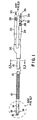
- Figure 1 is a plan view of an implantable lead in which the present invention may be practiced.
- Figure 2 is cross-sectional view through the lead of Figure 1, illustrating a first embodiment of the invention.
- Figure 3 is a side, cut-away view through the lead of Figure 1, illustrating the first embodiment of the invention.
- Figure 4 is a side, cut-away view through the distal portion of the lead of Figure 1, illustrating the first embodiment of the invention.
- Figure 5 is a side, cut-away view through the connector assembly of the lead of Figure 1, illustrating the first embodiment of the invention.
- Figure 6 is cross-sectional view through the lead of Figure 1, illustrating a further embodiment of the invention.
- Figure 7 is a side, cut-away view through the lead of Figure 1, illustrating the further embodiment of the invention.
- Figure 8 is a side, cut-away view through the a lead according to the present invention, illustrating an alternative mechanism for interconnecting a coiled conductor with a stranded conductor.
- Figure 9 is a plan view of a lead having a rotatable fixation helix, embodying the present invention.
- Figure 10 is a cross-sectional view through the lead of Figure 9.
- Figure 11 is a side, cut-away view through the distal portion of the lead of Figure 9.
- Figure 12 is a side, cut-away view through the proximal portion of the lead of Figure 9.
- Figure 1 is a plan view of a defibrillation lead of a lead in which the present invention is practiced.
- the present invention may also be usefully practiced in the context of other types of medical electrical leads, such as cardiac pacing leads, nerve and muscle stimulation leads, and so forth.
- the lead of Figure 1 is provided with an elongate insulative lead body 10, preferably fabricated of silicone rubber, polyurethane or other biocompatible elastomer. At the proximal end of the lead, it carries an elongate defibrillation electrode 12, a ring electrode 14 and a tip electrode 16, each coupled to a conductor located within the lead body 10. Tines 18 are provided in maintaining electrode 16 in contact with the tissue of the right ventricle. Electrodes 16, 14 and 12 may correspond generally to conventionally available pacing and defibrillation electrodes.
- the proximal end of the lead carries a connector assembly, beginning with a molded lead bifurcation 20, which splits off two of the conductors within lead body 10 to a bipolar, in-line connector assembly 24, generally corresponding to the IS-1 connector standard for pacing leads.
- Connector assembly 24 is provided with a first set of sealing rings 28, a connector ring 32, a second set of sealing rings 34 and connector pin 36.
- the connector pin 36 is coupled to the conductor which extends through the lead body 10 to tip electrode 16.
- Connector ring is coupled to the conductor which extends through the lead body 10 to ring electrode 14.
- the conductor coupled to defibrillation electrode 12 extends into connector assembly 22, which carries a set of sealing rings 26 and a connector pin 36, coupled to the conductor extending through lead body 10 to defibrillation electrode 12.
- the conductor coupling connector pin 36 to electrode 16 takes the form of a monofilar or multifilar coiled conductor to allow passage of a stylet therethrough, while the conductors coupling ring electrode 14 to connector ring 32 and coupling defibrillation electrode 12 to connector pin 30 take the form of bundled, stranded wires, provided with a coating of PTFE.
- the conductors coupling ring electrode 14 and defibrillation electrode 12 may take the form of any of the various conductor types known for use in conjunction with implantable electrical leads. If fewer electrodes are provided on the lead, correspondingly fewer conductors will be included.
- One or more physiologic sensors may be added to the lead or substituted for one or more of the illustrated electrodes.
- a stranded wire conductor which extends along a length of the coiled conductor and which serves as a mechanism for bridging a fracture of the coiled conductor which occurs between the ends of the stranded conductor.
- the stranded conductor also couples electrode 16 to connector pin 36, providing both an axial reinforcement and a redundant electrical connection, as described in more detail below.
- the electrical interconnection between the coiled and stranded conductors may simply be the contact between the two conductors which occurs as a result of both conductors being located in the same lumen of the lead.
- Figure 2 illustrates a cross-section through lead body 10, illustrating the inter-relation of the conductor lumens 100, 102 and 104 with compression lumens 106, 108 and 110, which are described in more detail in U.S. Patent No. 5,584,873, issued to Shoberg et al.
- lumens 100 and 102 contain conductors 112 and 114 which in the illustrated embodiment may take the form of PTFE coated bundled stranded wires having a generally straight configuration.
- conductors 112 and 114 may take the form of a PTFE coated, bundled, stranded 49 filar cable formed of seven strands, each strand formed of seven filars, as described in more detail in U.S. Patent No.
- Lumen 104 contains a conventional multifilar coiled conductor 116 and a small diameter bundled stranded wire conductor 118.
- Conductor 118 may take the form of a seven filar bundle or cable of MP35N or silver cored MP35N wire, as described in U.S. Patent No. 5,246,014, issued to Williams et al., such that conductor 118 corresponds generally to one of the seven strands that make up conductors 112 and 114.
- conductor 118 may have an outer diameter of about 0.075 mm (.003 inches).
- stranded conductor 118 is extremely resistant to fracturing in response to repeated flexure of the lead body and displays a high tensile strength.
- redundant, stranded conductor 118 will remain to provide for connection to the electrode to which coiled conductor 116 is coupled.
- the stranded and coiled conductors make contact with one another at multiple points along the lead body, so that a break of the coiled conductor occurring between the ends occurring between the ends of the stranded conductor will be bridged.
- conductor 118 may also be mechanically coupled to the coiled conductor 116 and thereby serve to maintain the structural integrity of the lead, preventing partial disassembly due to applied tensile forces. If the lead is removed, conductor 118 may thus also serve as a reinforcement, allowing traction force to be applied to the distal end of the lead during extraction. In either case, conductor 118 allows for continued functioning of the lead after fracture of the coiled conductor 116, allowing for replacement of the lead, when convenient, without interruption of the therapeutic function of the pacemaker or stimulator to which the lead is coupled.
- conductor 118 is uninsulated along its length and thus makes contact with conductor 116 at various points along the length of the lead.
- the conductor 118 will serve as both a redundant conductor, coupling the connector pin 36 to the electrode 16, and as a conductive bridge between the broken ends of the conductor 116, as it will be in contact with the conductor 116 on either side of the break.
- conductor 118 may be provided with an insulative coating of PTFE or other insulative material.
- conductor 118 will serve as a redundant connector, connecting connector pin 32 to electrode 16, and upon fracture of conductor 116, a substantial change in connector pin to electrode impedance will be manifested.
- this provides the physician and/or the device itself with a mechanism for detecting the fracture in 116.
- the fracture can be detected without the serious consequences which would otherwise be associated with disconnection of the electrode 16 from the connector pin 36.
- the device may respond to the change in lead impedance by noting the occurrence of a fracture in conductor 116 and may correspondingly alter its programmed parameters in order to restore performance essentially to that preceding the fracture of conductor 116.
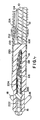
- FIG. 3 is a side, cutaway view through the lead of FIG. 1, illustrating the first embodiment of the present invention, also illustrated in FIG. 2.
- stranded conductor 118 is loosely spiraled around coiled conductor 116 along the length of the lead, facilitating flexure of the lead body and the conductors located therein. If the ends of conductor 118 are mechanically coupled to conductor 116, this structure also allows for a limited amount of axial elongation of the lead body and conductor 116 along the length of conductor 118. All other labeled elements correspond to those illustrated in FIG. 2.
- conductor 118 may be insulated or uninsulated, as discussed above, depending on whether contact between the two conductors along their length is desired.
- An alternative embodiment in which the stranded conductor is desired to be insulated from the coiled conductor along some portion of its length may employ a separate lumen in the lead body for the stranded conductor, intermediate its points of connection to the coiled conductor.
- An additional alternative as discussed below may employ a tubular, insulative sheath within or around coiled conductor 116 to insulate it from conductor 118.
- FIGs. 4 et seq. show basic mechanisms which may optionally be employed to mechanically interconnect the stranded conductor 118, the coiled conductor 116, electrode 16 and connector pin 36.
- These illustrated interconnection mechanisms are intended to be exemplary, and may of course, be employed in conjunction with other components of implantable leads, including other types of electrical connectors such as connector rings, corresponding to connector ring 32 and to interconnect these conductors with other types of electrodes and to interconnect these components with other lead components such as physiologic sensors such as pressure sensors, oxygen sensors, temperature sensors and the like.
- FIG 4 is a sectional view through the distal portion of the lead illustrated in Figure 1. In this view, the interconnection of conductor 116, conductor 118 and electrode 16 is visible. Extending distally from the defibrillation electrode 12, the lead takes the form of a molded piece part 228, which carries ring electrode 14, which is in turn coupled to stranded conductor 112 (not visible in this view). Electrode 16 as illustrated is a steroid-eluting electrode, provided with a monolithic controlled release device 222 located within a chamber within the electrode.
- Electrode 16 is coupled to a coiled conductor 116 and 118 by means of an external crimping sleeve 224, which compresses conductor 118 against conductor 116 and compresses conductor 116 against the proximal portion 220 of electrode 16.
- Other types of tip electrodes, including screw-in electrodes may of course be substituted for electrode 16.
- other mechanisms may be employed to interconnect conductors 118 and 116 and electrode 16, including welding, swaging, crimping and combinations thereof, including mechanisms as disclosed in commonly assigned U.S. Patent No. 5,676,694 by Boser et al, filed June 7, 1996 and U.S. Patent No. 6,026,567 by Swoyer et al., filed May 11, 1995.
- Conductor 114 passes through an internal lumen 100 within lead body 10, and has its insulation removed in areas in which it passes through the cross-bore crimp sleeve 212.
- the distal turn of electrode coil 12 can be seen at 12A as it passes through the perpendicular cross-bore through sleeve 212.
- the sleeve 212 is crimped to the conductor 114 and a portion of the distal turn of electrode coil 12 is inserted through the cross bore and the entry and exit points of the coil are laser welded to the sleeve.
- External polymeric sleeve 230 is slid over the distal ends of conductor coil 12, and the areas between the sleeve 230 lead body 10 is backfilled by means of medical adhesive or other polymeric material.
- the electrode coil 12 may be secured to the outer circumference of the lead body 10 by means of a backfilling process as described in U.S. Patent No. 4,934,049.
- Figure 4 shows the inter-connection of the stranded and coiled conductors at the tip electrode 16
- these conductors may instead be connected at a point proximal to the tip electrode, for example by use of a cross-bore crimp sleeve similar to sleeve 212, or by means of other types of welded, swaged or crimped connections as discussed above.
- FIG. 5 is a sectional view through the bipolar connector assembly 24 of the lead illustrated in Figure 1, illustrating the first embodiment of the invention.
- the proximal end of connector pin 36 is visible in cross-section, and connector ring 32 is visible in cross-section.
- Connector pin 36 is coupled to coiled conductor 116 by means of a swaging core 200, which compresses conductor coil 116 and stranded conductor 118 between the interior lumen of connector pin 36 and the outer surface of swaging core 200, in a conventional fashion.
- An insulative sleeve 206 surrounds conductors 116 and 118, and extends distally, back through the connector assembly into molded sealing ring sleeve 28 (Fig. 1).
- a molded sealing ring sleeve 34 Surrounding connector pin 36 is a molded sealing ring sleeve 34, which may be fabricated of silicone rubber, which in turn is mounted to a spacer 204 which is typically fabricated of a harder plastic, such as polyurethane. Spacer 204 is molded in situ between connector pin 36 and ring electrode 32, and is maintained in mechanical interconnection with electrode 32 by means of internal threading 208, as described in U.S. Patent No. 4,572,605.
- conductors 118 and 116 and connector pin 36 may be employed to interconnect conductors 118 and 116 and connector pin 36, including welding, swaging, crimping and combinations thereof, as described above. Additionally, these conductors may instead be connected at a point distal to the connector pin, for example by use of a cross-bore crimp sleeve similar to sleeve 212, or by means of other types of welded, swaged or crimped connections as discussed above.
- the internal structure of the leads may correspond to those illustrated in Figures 4 or 5 above, with the exception the stranded conductor 118 is simply not crimped, swaged or otherwise coupled to the connector pin, electrode or coiled conductor 118.
- the stranded conductor may extend the entire length of the coiled conductor or may extend over only a portion of the length of the coiled conductor.
- Figures 4 or 5 illustrate the coil and stranded conductor pair coupled to the connector pin and tip electrode, it should also be understood that the invention may also be usefully practiced in leads in which these conductors are coupled to other connector elements, other electrodes and/or physiologic sensors located on the lead body.
- the interconnection methods of Figures 4 and 5 may also be used to connect the stranded conductor 118 to the coiled conductor 116 and to such other lead components.
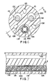
- Figure 6 illustrates a cross section through another embodiment of the invention. All numbered components correspond to identically numbered components in the Figures above.
- the stranded conductor 118 is located outside of coiled conductor 116 and is insulated from conductor 116 over at least a portion of its length by means of an insulative tube 300, located exterior to conductor 116.
- Tube 300 may be formed of PTFE or other insulative biocompatible plastic, and may extend over all or some of the length of coiled conductor 116.
- it is desirable that the ends of stranded conductor 118 are mechanically coupled to the coiled conductor 116 on either side of the tube 300.
- Figure 7 illustrates a side, cut-away view through the embodiment of the invention as illustrated in Figure 6. All numbered components correspond to identically numbered components in the Figures above.
- Figure 8 illustrates an alternative mechanism for interconnecting a stranded conductor 412 with a coiled conductor 416, both located within an internal lumen of lead body 410.
- Conductive crimp sleeve 418 is crimped to coiled conductor 416 by crimps 420.
- a cylindrical crimping core (not illustrated) may be inserted into the lumen of coiled conductor 416, prior to crimping.
- Stranded conductor 412 is coupled to the crimp sleeve 418 by means of conductive sleeve 422, by the following methods.
- Stranded conductor 412 may be threaded through sleeve 422, which is then pushed onto crimping core 418, pulling stranded conductor 412 along and compressing it between crimp sleeve 418 and sleeve 422.
- the interior of sleeve 422 may be provided with threads or other internal texturing to frictionally engage stranded conductor 412.
- stranded conductor 412 may arranged alongside crimp core 418 and sleeve 422, may then be pushed onto crimp core 418, compressing conductor 412 between crimp sleeve 418 and sleeve 422.
- the exterior of crimp of sleeve 418 may be provided with threads or other external texturing to frictionally engage stranded conductor 412.
- sleeve 422 may simply be crimped around stranded conductor 412 and crimping sleeve 418.
- Crimp sleeve 418 may take the form of a portion of a connector pin or ring on the proximal end of the lead body or a portion of an electrode or other sensor on the distal portion of the lead body, or may simply be a cylindrical sleeve, employed to couple the stranded and coiled conductors at some point along the lead body.
- Plastic Sleeve 414 insulated stranded conductor 412 from coiled conductor 416 over a portion of their lengths.
- Figure 9 is a plan view of a defibrillation lead in which the present invention is practiced, employing a tip electrode taking the form of a rotatable fixation helix 316.
- the lead of Figure 9 is provided with an elongate insulative lead body 310, preferably fabricated of silicone rubber, polyurethane or other biocompatible elastomer.
- a ring electrode 314 and a rotatable helical tip electrode 316 rotatably and advancably mounted in insulative electrode head 318.
- Each electrode is coupled to a conductor located within the lead body 310.
- Electrodes 314 and 312 may correspond generally to conventionally available pacing and defibrillation electrodes.
- a cap member 319 is located at the distal end of electrode head 318 and serves to retain a monolithic controlled release device as discussed below.
- the proximal end of the lead carries a connector assembly, beginning with a molded lead bifurcation 320, which splits off two of the conductors within lead body 310 to a bipolar, in-line connector assembly 324, generally corresponding to the IS-1 connector standard for pacing leads.
- Connector assembly 324 is provided with a first set of sealing rings 328, a connector ring 332, a second sealing rings 334 and connector pin 336.
- Connector pin 336 is rotatably mounted and is coupled to a rotatably mounted conductor which extends through the lead body 310 to helical electrode 316.
- Connector ring 332 is coupled to a conductor which extends through the lead body 310 to ring electrode 314.
- a conductor coupled to defibrillation electrode 312 extends into connector assembly 322, which carries a set of sealing rings 326 and is coupled to connector pin 336.
- the conductor coupling connector pin 336 to electrode 316 takes the form of a monofilar or multifilar coiled conductor to allow passage of a stylet therethrough
- the conductors coupling ring electrode 314 to connector ring 332 and coupling defibrillation electrode 312 to connector pin 330 take the form of bundled, stranded wires, provided with a coating of PTFE.
- the conductors coupling ring electrode 314 and defibrillation electrode 312 may take the form of any of the various conductor types known for use in conjunction with implantable electrical leads. If fewer electrodes are provided on the lead, correspondingly fewer conductors will be included.
- One or more physiologic sensors may be added to the lead or substituted for one or more of the illustrated electrodes.
- a stranded wire conductor which extends along a length of the coiled conductor and which serves a mechanism for bridging a fracture of the coiled conductor which occurs between the ends of the stranded conductor, as discussed above.
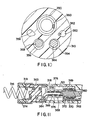
- Figure 10 illustrates a cross section through the lead illustrated in Figure 9.
- the lead body is provided with five lumens, including three circular lumens 350, 354 and 356 and two teardrop-shaped compression lumens 352 and 358.
- Coiled conductor 360 is coupled to helical electrode 316 (Fig. 9) and connector pin 336 (Fig. 9). On rotation of connector pin 336, conductor 360 transmits torque to rotate electrode 316, advancing it out the distal end of electrode head 318 (Fig. 9) and screwing it into heart tissue.
- Conductors 364 and 368 as illustrated are stranded or cabled conductors corresponding to conductors 112 and 114 (Fig.
- Stranded conductor 362 is coupled to coiled conductor 360 adjacent the proximal and distal ends of the lead, providing a redundant connector and tensile reinforcement in the same fashion as conductor 118 (Fig. 2) discussed above.
- the wall of lead body 310 separating lumens 350 and 352 insulates conductor 362 from conductor 360 between the points at which they are electrically coupled. Electrical interconnection of conductors 360 and 362 is by means of rotating electrical couplings as described in conjunction with Figs. 11 and 12 below, which allow rotation of coil conductor 360 relative to stranded conductor 362.
- Electrode head 318 is fabricated of a rigid, biocompatible plastic such as a polyurethane, and is provided with an internal longitudinal lumen 321.
- Cap 319 retains a toroidal monolithic controlled release device 374, which serves to elute an anti-inflammatory steroid such as sodium dexamethasone phosphate, as described in U.S. Patent No. 4,972,848, issued to DiDomrnico.
- Guide 363 engages helical electrode 316 such that rotation of the electrode serves to advance it out the distal end of electrode head 318 or withdraw it into lumen 321.
- Coiled conductor 360 is mechanically and electrically coupled to the proximal end of electrode 316 by conductive crimp sleeve 368, compressed by crimps 376.
- Crimp sleeve 368 is provided with a circumferential shoulder 378 which serves to limit distal movement of helix 316 by contact with radio-opaque marker ring 364 and which serves to limit proximal movement of helix 316 by contact with conductive ferrule 369.
- ferrule 369 which is crimped to stranded conductor 362 by crimp 370 and is provided with contact means 372 for coupling to conductive crimp sleeve 368.
- the contact means 372 is a conductive spring with individual turns offset from one another to springingly contact both ferrule 369 and crimp sleeve 368 while allowing rotation and longitudinal movement of crimp sleeve 368, in a manner analogous to that illustrated in U.S. patent No. 4,557,643.
- coupling means in the form of other types of spring contacts, fine wire brushes or other known mechanisms for rotatable electrical couplings may be substituted.
- Figure 12 shows a side, cut-away view through the lead of Figure 9 in the vicinity of bifurcation 320.
- coiled conductor 360 and stranded conductors 362 and 364 are visible, exiting from lead body 310 and entering into molded bifurcation 320.
- Interconnection of stranded conductor 362 and coiled conductor 360 is accomplished by ferrule 380 coupled to conductor 362 by crimp 382, crimp sleeve 386 coupled to coiled conductor 360 by crimps 388 and conductive spring 384.
- ferrule 380 coupled to conductor 362 by crimp 382
- crimp sleeve 386 coupled to coiled conductor 360 by crimps 388 and conductive spring 384.
- the known mechanisms for making a rotating electrical connection may be substituted. While the rotatable coiled conductor in this embodiment is coupled to a helical electrode, it may alternatively be coupled to any other electrode which is deployed or manipulated by applied torque and may also be employed with any other mechanism requiring both applied torque and an electrical connection.
Claims (22)
- Implantierbare medizinische Leitung mit:dadurch gekennzeichnet, daß die Litze außerhalb des inneren Lumens des gewickelten Leiters (116) über eine Strecke entlang dem Leitungskörper angeordnet ist.einem länglichen Leitungskörper (10), der in seinem Innern ein längliches Lumen (100, 102, 104) darin aufweist;einem länglichen gewickelten Leiter (116), der im Lumen (104) des Leitungskörpers (10) befestigt ist, wobei der gewickelte Leiter selbst ein inneres Lumen definiert;einer mehrsträngigen, im wesentlichen geraden Litze (118), die entlang dem Leitungskörper verläuft sowie an einer ersten Stelle und an einer distal und in Abstand von dieser befindlichen zweiten Stelle elektrisch mit dem gewickelten Leiter gekoppelt ist,
- Leitung nach Anspruch 1, wobei die Leitung mit einem elektrischen Anschluß (36) versehen ist, der an einem proximalen Ende des Leitungskörpers (10) angeordnet und mit dem gewickelten Leiter (116) verbunden ist.
- Leitung nach Anspruch 2, wobei die Litze (118) und der gewickelte Leiter (116) elektrisch und mechanisch an den Anschluß (36) gekoppelt sind.
- Leitung nach einem der vorhergehenden Ansprüche, die mit einem an dem Leitungskörper (10) angeordneten elektrischen Bauteil versehen ist, wobei der gewickelte Leiter (116) mit dem elektrischen Bauteil gekoppelt ist.
- Leitung nach Anspruch 4, wobei der gewickelte Leiter (116) und die Litze (118) elektrisch und mechanisch an das elektrische Bauteil gekoppelt sind.
- Leitung nach Anspruch 4 oder 5, wobei das elektrische Bauteil eine Elektrode (12, 16) ist.
- Leitung nach einem der vorhergehenden Ansprüche, wobei die Litze (118) zwischen der ersten und der zweiten Stelle gegen den gewickelten Leiter (116) isoliert ist.
- Leitung nach einem der vorhergehenden Ansprüche, wobei die Litze (118) und der gewickelte Leiter (116) beide innerhalb des Lumens des Leitungskörpers (10) angeordnet sind.
- Leitung nach einem der vorhergehenden Ansprüche, wobei die Litze einen siebensträngigen Leiter umfaßt.
- Leitung nach Anspruch 9, wobei der gewickelte Leiter (118) einen Außendurchmesser von etwa 0,075 mm (0,003 Zoll) aufweist.
- Leitung nach einem der vorhergehenden Ansprüche, wobei die Litze (118) und der gewickelte Leiter (116) elektrisch und mechanisch miteinander gekoppelt sind.
- Leitung nach Anspruch 11, wobei die Litze (118) und der gewickelte Leiter (116) an der ersten und der zweiten Stelle elektrisch und mechanisch miteinander gekoppelt sind.
- Leitung nach einem der vorhergehenden Ansprüche, wobei die Litze (118) und der gewickelte Leiter (116) entlang einem Abschnitt des gewickelten Leiters zwischen der ersten und der zweiten Stelle elektrisch gegeneinander isoliert sind.
- Leitung nach Anspruch 13, wobei die Litze (118) und der gewickelte Leiter (116) entlang einem Abschnitt des gewickelten Leiters zwischen der ersten und der zweiten Stelle mittels einer rohrförmigen isolierenden Hülle (300) elektrisch gegeneinander isoliert sind.
- Leitung nach Anspruch 14, wobei die rohrförmige Hülle (300) außerhalb des gewickelten Leiters (116) und die Litze (118) außerhalb der rohrförmigen Hülle angeordnet ist.
- Leitung nach einem der vorhergehenden Ansprüche außer Anspruch 8 un den davon abhängigen Ansprüchen, wobei die Litze außerhalb des Lumens des Leitungskörpers angeordnet ist.
- Leitung nach Anspruch 16, wobei der Leitungskörper (10) mit einem zusätzlichen längs verlaufenden Lumen versehen und die Litze (118) in diesem zusätzlichen Lumen angeordnet ist.
- Leitung nach einem der vorhergehenden Ansprüche, wobei der gewickelte Leiter (116) drehbar in dem Lumen befestigt ist.
- Leitung nach Anspruch 18, wobei die Leitung eine Einrichtung umfaßt, um die Litze (118) mit dem gewickelten Leiter (116) zu koppeln, während sich der gewickelte Leiter dreht.
- Leitung nach Anspruch 18 oder 19, wobei die Leitung einen drehbar gelagerten elektrischen Anschluß umfaßt, der in einem proximalen Abschnitt des Leitungskörpers angeordnet und mit dem gewickelten Leiter (116) gekoppelt ist.
- Leitung nach Anspruch 19 oder 20, wobei die Leitung eine drehbar gelagerte Elektrode umfaßt, die an einem distalen Abschnitt des Elektrodenkörpers angeordnet und mit dem gewickelten Leiter (116) gekoppelt ist.
- Leitung nach Anspruch 1 oder 2, wobei die Litze außerhalb des Lumens des Leitungskörpers angeordnet ist.
Priority Applications (1)
| Application Number | Priority Date | Filing Date | Title |
|---|---|---|---|
| EP00109150A EP1023915B1 (de) | 1997-04-21 | 1998-03-18 | Leitung für medizinische Zwecke |
Applications Claiming Priority (5)
| Application Number | Priority Date | Filing Date | Title |
|---|---|---|---|
| US08/843,763 US6285910B1 (en) | 1997-04-21 | 1997-04-21 | Medical electrical lead |
| US843765 | 1997-04-21 | ||
| US843763 | 1997-04-21 | ||
| US08/843,765 US5954759A (en) | 1997-04-21 | 1997-04-21 | Fracture resistant medical electrical lead |
| PCT/US1998/005323 WO1998047560A1 (en) | 1997-04-21 | 1998-03-18 | Medical electrical lead |
Related Child Applications (1)
| Application Number | Title | Priority Date | Filing Date |
|---|---|---|---|
| EP00109150A Division EP1023915B1 (de) | 1997-04-21 | 1998-03-18 | Leitung für medizinische Zwecke |
Publications (2)
| Publication Number | Publication Date |
|---|---|
| EP0980281A1 EP0980281A1 (de) | 2000-02-23 |
| EP0980281B1 true EP0980281B1 (de) | 2001-06-27 |
Family
ID=27126441
Family Applications (2)
| Application Number | Title | Priority Date | Filing Date |
|---|---|---|---|
| EP00109150A Expired - Lifetime EP1023915B1 (de) | 1997-04-21 | 1998-03-18 | Leitung für medizinische Zwecke |
| EP98911775A Expired - Lifetime EP0980281B1 (de) | 1997-04-21 | 1998-03-18 | Medizinische elektrische leitung |
Family Applications Before (1)
| Application Number | Title | Priority Date | Filing Date |
|---|---|---|---|
| EP00109150A Expired - Lifetime EP1023915B1 (de) | 1997-04-21 | 1998-03-18 | Leitung für medizinische Zwecke |
Country Status (4)
| Country | Link |
|---|---|
| EP (2) | EP1023915B1 (de) |
| AU (1) | AU6564998A (de) |
| DE (2) | DE69820889T2 (de) |
| WO (1) | WO1998047560A1 (de) |
Families Citing this family (13)
| Publication number | Priority date | Publication date | Assignee | Title |
|---|---|---|---|---|
| US6249709B1 (en) | 1999-02-18 | 2001-06-19 | Intermedics Inc. | Endocardial defibrillation lead with multi-lumen body and axially mounted distal electrode |
| US6216045B1 (en) | 1999-04-26 | 2001-04-10 | Advanced Neuromodulation Systems, Inc. | Implantable lead and method of manufacture |
| US6289251B1 (en) * | 1999-11-01 | 2001-09-11 | Medtronic, Inc. | High strength medical electrical lead |
| US7395116B2 (en) | 2004-08-19 | 2008-07-01 | Medtronic, Inc. | Lead body-to-connector transition zone |
| US7831311B2 (en) | 2004-10-21 | 2010-11-09 | Medtronic, Inc. | Reduced axial stiffness implantable medical lead |
| US7761170B2 (en) | 2004-10-21 | 2010-07-20 | Medtronic, Inc. | Implantable medical lead with axially oriented coiled wire conductors |
| US7519432B2 (en) | 2004-10-21 | 2009-04-14 | Medtronic, Inc. | Implantable medical lead with helical reinforcement |
| US7680544B1 (en) | 2006-11-07 | 2010-03-16 | Pacesetter, Inc. | Fatigue resistant design for leads employing multi-strand cables as primary conductors |
| US8170691B2 (en) * | 2007-04-27 | 2012-05-01 | St. Jude Medical Ab | Medical implantable lead |
| US20110160830A1 (en) * | 2009-12-31 | 2011-06-30 | Morris Kimberly A | Implantable leads with an axial reinforcement member |
| CN103648580B (zh) * | 2012-06-28 | 2016-08-17 | 上海微创医疗器械(集团)有限公司 | 主动心脏电导线的组装 |
| WO2014025402A2 (en) * | 2012-08-09 | 2014-02-13 | Cardiac Pacemakers, Inc. | Reinforced coil created from polymer coated wire for improved torque transfer |
| US9907948B2 (en) | 2013-06-07 | 2018-03-06 | Cardiac Pacemakers, Inc. | Electrical and mechanical connection for coiled stimulation/sensing lead conductors |
Family Cites Families (13)
| Publication number | Priority date | Publication date | Assignee | Title |
|---|---|---|---|---|
| US3572344A (en) | 1968-12-31 | 1971-03-23 | Medtronic Inc | Electrode apparatus with lead construction |
| US3844292A (en) | 1972-06-09 | 1974-10-29 | Medtronic Inc | Intravascular lead assembly |
| US4033355A (en) | 1975-11-28 | 1977-07-05 | Cardiac Pacemakers, Inc. | Electrode lead assembly for implantable devices and method of preparing same |
| DE3640033A1 (de) * | 1986-11-24 | 1988-05-26 | Siemens Ag | Herzschrittmacherelektrode |
| US5246014A (en) | 1991-11-08 | 1993-09-21 | Medtronic, Inc. | Implantable lead system |
| US5231996A (en) | 1992-01-28 | 1993-08-03 | Medtronic, Inc. | Removable endocardial lead |
| IT1257824B (it) * | 1992-06-09 | 1996-02-13 | Xtrode Srl | Dispositivo adattatore per elettrocateteri monopolari |
| US5324321A (en) * | 1992-12-22 | 1994-06-28 | Medtronic, Inc. | Medical electrical lead having sigmoidal conductors and non-circular lumens |
| NL9300670A (nl) | 1993-04-20 | 1994-11-16 | Cordis Europ | Catheter met elektrisch goed geleidende draadversterking. |
| US5466253A (en) | 1993-04-27 | 1995-11-14 | Pacesetter, Inc. | Crush resistant multi-conductor lead body |
| ITRM940130A1 (it) * | 1994-03-10 | 1995-09-11 | P A & M Spa | Elemento di sicurezza atto a garantire nel tempo l'affidabilita' elettrica degli elettrodocateteri per la stimolazione elettrica del |
| IT1273836B (it) * | 1994-03-15 | 1997-07-10 | Xtrode Srl | Perfezionamento ad un dispositivo adattatore per elettrocateteri |
| US5584873A (en) | 1995-05-08 | 1996-12-17 | Medtronic, Inc. | Medical lead with compression lumens |
-
1998
- 1998-03-18 AU AU65649/98A patent/AU6564998A/en not_active Abandoned
- 1998-03-18 WO PCT/US1998/005323 patent/WO1998047560A1/en active IP Right Grant
- 1998-03-18 DE DE69820889T patent/DE69820889T2/de not_active Expired - Lifetime
- 1998-03-18 DE DE69801001T patent/DE69801001T2/de not_active Expired - Lifetime
- 1998-03-18 EP EP00109150A patent/EP1023915B1/de not_active Expired - Lifetime
- 1998-03-18 EP EP98911775A patent/EP0980281B1/de not_active Expired - Lifetime
Also Published As
| Publication number | Publication date |
|---|---|
| EP1023915A1 (de) | 2000-08-02 |
| DE69801001T2 (de) | 2002-03-14 |
| EP0980281A1 (de) | 2000-02-23 |
| EP1023915B1 (de) | 2004-01-02 |
| AU6564998A (en) | 1998-11-13 |
| DE69801001D1 (de) | 2001-08-02 |
| DE69820889D1 (de) | 2004-02-05 |
| WO1998047560A1 (en) | 1998-10-29 |
| DE69820889T2 (de) | 2004-07-15 |
Similar Documents
| Publication | Publication Date | Title |
|---|---|---|
| US6018683A (en) | Medical electrical lead having coiled and stranded conductors | |
| US6785576B2 (en) | Medical electrical lead | |
| US6052625A (en) | Extractable implantable medical lead | |
| US6801809B2 (en) | Extractable implantable medical lead | |
| US6026567A (en) | Medical lead with stranded conductors | |
| US5676694A (en) | Medical electrical lead | |
| US5954759A (en) | Fracture resistant medical electrical lead | |
| US5935159A (en) | Medical electrical lead | |
| US7174220B1 (en) | Construction of a medical electrical lead | |
| US6920361B2 (en) | Reverse wound electrodes | |
| US5466253A (en) | Crush resistant multi-conductor lead body | |
| US6289251B1 (en) | High strength medical electrical lead | |
| US6253111B1 (en) | Multi-conductor lead | |
| EP1128869B1 (de) | Entfernbare implantierbare medizinische leitung | |
| US6038463A (en) | Medical electrical lead | |
| US5683444A (en) | Composite electrode | |
| EP0980281B1 (de) | Medizinische elektrische leitung | |
| EP1793889A1 (de) | Implantierbare medizinische leitung mit overlay | |
| US20060095107A1 (en) | Flexible lead body for implantable stimulation leads | |
| US20040249430A1 (en) | Implantable medical electrical lead | |
| WO2007016019A1 (en) | Medical electrical lead connector ring |
Legal Events
| Date | Code | Title | Description |
|---|---|---|---|
| PUAI | Public reference made under article 153(3) epc to a published international application that has entered the european phase |
Free format text: ORIGINAL CODE: 0009012 |
|
| 17P | Request for examination filed |
Effective date: 19991103 |
|
| AK | Designated contracting states |
Kind code of ref document: A1 Designated state(s): DE FR GB IT NL SE |
|
| 17Q | First examination report despatched |
Effective date: 20000412 |
|
| RIN1 | Information on inventor provided before grant (corrected) |
Inventor name: HEBZYNSKI, ANNETTE Inventor name: SWOYER, JOHN, M. Inventor name: WAHLSTROM, DALE, A. Inventor name: HUEPENBECKER, GEORGE, M. Inventor name: VERNESS, DAVID, D. |
|
| GRAG | Despatch of communication of intention to grant |
Free format text: ORIGINAL CODE: EPIDOS AGRA |
|
| GRAG | Despatch of communication of intention to grant |
Free format text: ORIGINAL CODE: EPIDOS AGRA |
|
| GRAH | Despatch of communication of intention to grant a patent |
Free format text: ORIGINAL CODE: EPIDOS IGRA |
|
| GRAH | Despatch of communication of intention to grant a patent |
Free format text: ORIGINAL CODE: EPIDOS IGRA |
|
| GRAA | (expected) grant |
Free format text: ORIGINAL CODE: 0009210 |
|
| ITF | It: translation for a ep patent filed |
Owner name: BARZANO' E ZANARDO ROMA S.P.A. |
|
| AK | Designated contracting states |
Kind code of ref document: B1 Designated state(s): DE FR GB IT NL SE |
|
| REF | Corresponds to: |
Ref document number: 69801001 Country of ref document: DE Date of ref document: 20010802 |
|
| ET | Fr: translation filed | ||
| REG | Reference to a national code |
Ref country code: GB Ref legal event code: IF02 |
|
| PLBE | No opposition filed within time limit |
Free format text: ORIGINAL CODE: 0009261 |
|
| STAA | Information on the status of an ep patent application or granted ep patent |
Free format text: STATUS: NO OPPOSITION FILED WITHIN TIME LIMIT |
|
| 26N | No opposition filed | ||
| PGFP | Annual fee paid to national office [announced via postgrant information from national office to epo] |
Ref country code: SE Payment date: 20040303 Year of fee payment: 7 |
|
| PG25 | Lapsed in a contracting state [announced via postgrant information from national office to epo] |
Ref country code: SE Free format text: LAPSE BECAUSE OF NON-PAYMENT OF DUE FEES Effective date: 20050319 |
|
| EUG | Se: european patent has lapsed | ||
| PGFP | Annual fee paid to national office [announced via postgrant information from national office to epo] |
Ref country code: GB Payment date: 20070202 Year of fee payment: 10 |
|
| PGFP | Annual fee paid to national office [announced via postgrant information from national office to epo] |
Ref country code: NL Payment date: 20070214 Year of fee payment: 10 |
|
| PGFP | Annual fee paid to national office [announced via postgrant information from national office to epo] |
Ref country code: IT Payment date: 20080321 Year of fee payment: 11 |
|
| GBPC | Gb: european patent ceased through non-payment of renewal fee |
Effective date: 20080318 |
|
| PG25 | Lapsed in a contracting state [announced via postgrant information from national office to epo] |
Ref country code: NL Free format text: LAPSE BECAUSE OF NON-PAYMENT OF DUE FEES Effective date: 20081001 |
|
| NLV4 | Nl: lapsed or anulled due to non-payment of the annual fee |
Effective date: 20081001 |
|
| PG25 | Lapsed in a contracting state [announced via postgrant information from national office to epo] |
Ref country code: GB Free format text: LAPSE BECAUSE OF NON-PAYMENT OF DUE FEES Effective date: 20080318 |
|
| PG25 | Lapsed in a contracting state [announced via postgrant information from national office to epo] |
Ref country code: IT Free format text: LAPSE BECAUSE OF NON-PAYMENT OF DUE FEES Effective date: 20090318 |
|
| PGFP | Annual fee paid to national office [announced via postgrant information from national office to epo] |
Ref country code: FR Payment date: 20130405 Year of fee payment: 16 Ref country code: DE Payment date: 20130327 Year of fee payment: 16 |
|
| REG | Reference to a national code |
Ref country code: DE Ref legal event code: R119 Ref document number: 69801001 Country of ref document: DE |
|
| REG | Reference to a national code |
Ref country code: FR Ref legal event code: ST Effective date: 20141128 |
|
| REG | Reference to a national code |
Ref country code: DE Ref legal event code: R119 Ref document number: 69801001 Country of ref document: DE Effective date: 20141001 |
|
| PG25 | Lapsed in a contracting state [announced via postgrant information from national office to epo] |
Ref country code: FR Free format text: LAPSE BECAUSE OF NON-PAYMENT OF DUE FEES Effective date: 20140331 Ref country code: DE Free format text: LAPSE BECAUSE OF NON-PAYMENT OF DUE FEES Effective date: 20141001 |