EP0980130A1 - Method for controlling the rapid charging of an alkaline electrolyte industrial accumulator - Google Patents
Method for controlling the rapid charging of an alkaline electrolyte industrial accumulator Download PDFInfo
- Publication number
- EP0980130A1 EP0980130A1 EP99401903A EP99401903A EP0980130A1 EP 0980130 A1 EP0980130 A1 EP 0980130A1 EP 99401903 A EP99401903 A EP 99401903A EP 99401903 A EP99401903 A EP 99401903A EP 0980130 A1 EP0980130 A1 EP 0980130A1
- Authority
- EP
- European Patent Office
- Prior art keywords
- charge
- voltage
- accumulator
- temperature
- uref
- Prior art date
- Legal status (The legal status is an assumption and is not a legal conclusion. Google has not performed a legal analysis and makes no representation as to the accuracy of the status listed.)
- Granted
Links
- 238000000034 method Methods 0.000 title claims abstract description 16
- 239000003792 electrolyte Substances 0.000 title claims description 9
- 238000007599 discharging Methods 0.000 claims description 3
- 229910052987 metal hydride Inorganic materials 0.000 abstract description 2
- PXHVJJICTQNCMI-UHFFFAOYSA-N nickel Substances [Ni] PXHVJJICTQNCMI-UHFFFAOYSA-N 0.000 abstract 2
- 239000003990 capacitor Substances 0.000 abstract 1
- 230000017525 heat dissipation Effects 0.000 abstract 1
- 238000005259 measurement Methods 0.000 abstract 1
- 150000004681 metal hydrides Chemical class 0.000 abstract 1
- 229910000652 nickel hydride Inorganic materials 0.000 abstract 1
- 230000037213 diet Effects 0.000 description 5
- 235000005911 diet Nutrition 0.000 description 5
- 238000012423 maintenance Methods 0.000 description 5
- 229910018095 Ni-MH Inorganic materials 0.000 description 4
- 229910018477 Ni—MH Inorganic materials 0.000 description 4
- 238000010438 heat treatment Methods 0.000 description 3
- QVGXLLKOCUKJST-UHFFFAOYSA-N atomic oxygen Chemical compound [O] QVGXLLKOCUKJST-UHFFFAOYSA-N 0.000 description 2
- 238000001514 detection method Methods 0.000 description 2
- 239000000463 material Substances 0.000 description 2
- 239000002184 metal Substances 0.000 description 2
- 229910052751 metal Inorganic materials 0.000 description 2
- 229910052760 oxygen Inorganic materials 0.000 description 2
- 239000001301 oxygen Substances 0.000 description 2
- 229910003307 Ni-Cd Inorganic materials 0.000 description 1
- 239000004480 active ingredient Substances 0.000 description 1
- 230000032683 aging Effects 0.000 description 1
- 238000006243 chemical reaction Methods 0.000 description 1
- 230000006378 damage Effects 0.000 description 1
- 230000001627 detrimental effect Effects 0.000 description 1
- 238000001035 drying Methods 0.000 description 1
- 230000000694 effects Effects 0.000 description 1
- 230000000977 initiatory effect Effects 0.000 description 1
- 238000013021 overheating Methods 0.000 description 1
- 230000003647 oxidation Effects 0.000 description 1
- 238000007254 oxidation reaction Methods 0.000 description 1
- 230000002028 premature Effects 0.000 description 1
- 230000007704 transition Effects 0.000 description 1
Images

Classifications
-
- H—ELECTRICITY
- H02—GENERATION; CONVERSION OR DISTRIBUTION OF ELECTRIC POWER
- H02J—CIRCUIT ARRANGEMENTS OR SYSTEMS FOR SUPPLYING OR DISTRIBUTING ELECTRIC POWER; SYSTEMS FOR STORING ELECTRIC ENERGY
- H02J7/00—Circuit arrangements for charging or depolarising batteries or for supplying loads from batteries
- H02J7/007—Regulation of charging or discharging current or voltage
- H02J7/00712—Regulation of charging or discharging current or voltage the cycle being controlled or terminated in response to electric parameters
- H02J7/007182—Regulation of charging or discharging current or voltage the cycle being controlled or terminated in response to electric parameters in response to battery voltage
Landscapes
- Engineering & Computer Science (AREA)
- Power Engineering (AREA)
- Secondary Cells (AREA)
- Battery Electrode And Active Subsutance (AREA)
Abstract
Description
La présente invention concerne un procédé de contrôle utilisable pour charger rapidement un accumulateur industriel à électrolyte alcalin, notamment du type "sans maintenance" ou du type "étanche", en particulier un accumulateur nickel-métal hydrurable (Ni-MH).The present invention relates to a control method usable for quickly charge an industrial battery with alkaline electrolyte, especially "maintenance-free" or "waterproof" type, in particular an accumulator nickel-hydrurable metal (Ni-MH).
Un accumulateur est dit "industriel" lorsqu'il possède une forte capacité supérieure à 10Ah, et généralement comprise entre 50Ah et 200Ah. Ces accumulateurs ont habituellement un conteneur de forme prismatique en matériau plastique contenant des électrodes planes. Leur géométrie parallélépipédique et la nature de leur bac ne leur permettent pas de résister à des surpressions importantes et leur pression interne maximale est de l'ordre de 1 à 2 bars.An accumulator is said to be "industrial" when it has a high capacity greater than 10Ah, and generally between 50Ah and 200Ah. These accumulators usually have a prismatic container made of material plastic containing flat electrodes. Their parallelepiped geometry and the nature of their tank does not allow them to resist overpressures significant and their maximum internal pressure is of the order of 1 to 2 bars.
Les accumulateurs industriels du type dit "sans maintenance" d'une part et du type dit "étanche" d'autre part présentent l'avantage de ne pas nécessiter de remise à niveau de l'électrolyte aqueux pendant toute leur durée d'utilisation, contrairement aux accumulateurs industriels du type dit "ouvert classique" ou du type dit "ouvert à maintenance allégée". Les batteries de tels accumulateurs sont notamment destinés à la traction de véhicules électriques. Dans cette application la durée de vie requise est d'environ 1 500 cycles de charge/décharge sur une période estimée à 10 ans. Une durée de vie aussi longue ne peut être atteinte que par une stricte limitation de la surcharge. En outre une utilisation de type "flotte" de ces véhicules impose de pouvoir effectuer une recharge de courte durée, par exemple 40% de la capacité nominale rechargée en moins de 15 minutes en garantissant l'absence de surcharge.Industrial accumulators of the so-called "maintenance-free" type on the one hand and of the so-called "waterproof" type on the other hand have the advantage of not requiring replenishment of the aqueous electrolyte throughout their period of use, unlike industrial accumulators of the so-called "classic open" type or type called "open with reduced maintenance". The batteries of such accumulators are in particular intended for the traction of electric vehicles. In this application the required service life is approximately 1,500 charge / discharge cycles over one estimated period of 10 years. Such a long service life can only be achieved by a strict limitation of the overload. In addition, a "fleet" type use of these vehicles require the ability to perform a short-term recharge, by example 40% of nominal capacity recharged in less than 15 minutes in guaranteeing the absence of overload.
Au cours de la phase de charge d'un accumulateur à électrolyte alcalin se produisent respectivement l'oxydation et la réduction des matières électrochimiquement actives des électrodes positives et négatives. Ces réactions se produisent sans dégagement gazeux. Lorsque la matière active positive est entièrement oxydée, l'accumulateur entre dans la phase de surcharge. Un dégagement abondant d'oxygène gazeux apparaít sur l'électrode positive. During the charging phase of an alkaline electrolyte accumulator produce respectively oxidation and reduction of materials electrochemically active positive and negative electrodes. These reactions are produce without gassing. When the positive active ingredient is fully oxidized, the accumulator enters the overcharging phase. A abundant release of gaseous oxygen appears on the positive electrode.
En régime rapide, l'oxygène dégagé n'a pas le temps d'être réduit (ou recombiné) à l'électrode négative. Cela provoque simultanément l'augmentation de la température et de la pression interne de l'accumulateur. Les accumulateurs industriels du type "sans maintenance" ou du type "étanche" ont une pression maximale de fonctionnement de l'ordre de 2 bars. L'augmentation de la pression interne conduit à l'ouverture de la soupape, donc à une perte d'électrolyte et une réduction de la durée de vie de la batterie par assèchement. En outre, il se produit un échauffement important qui est préjudiciable à la durée de vie de l'accumulateur.In fast regime, the released oxygen does not have time to be reduced (or recombined) to the negative electrode. This simultaneously causes the increase the temperature and the internal pressure of the accumulator. Accumulators "maintenance free" or "waterproof" type manufacturers have pressure maximum operating in the order of 2 bars. Increased pressure internal leads to the opening of the valve, thus to a loss of electrolyte and a reduction of battery life by drying. In addition, it occurs significant overheating which is detrimental to the service life of the accumulator.
Il est donc nécessaire de disposer d'un procédé permettant de recharger une batterie industrielle à électrolyte alcalin, notamment du type "sans maintenance" ou du type "étanche", dans un temps bref tout en évitant sa surcharge : la charge doit être interrompue au plus tard lorsque le taux de charge atteint 100%. Ce procédé doit en outre être applicable quel que soit l'état de charge initial de la batterie et quelle que soit sa température.It is therefore necessary to have a process for recharging an industrial battery with alkaline electrolyte, in particular of the type "without maintenance "or" waterproof "type, in a short time while avoiding its overload: the charge must be interrupted at the latest when the charge rate reaches 100%. This process must also be applicable regardless of the state of initial charge of the battery and whatever its temperature.
On a déjà proposé les critères de fin de charge comme le contrôle de l'augmentation de la température (+Δ) d'un accumulateur, la vitesse d'évolution de la température (d/dt), ou encore l'augmentation relative de la température de l'accumulateur par rapport à une loi d'échauffement.We have already proposed end-of-charge criteria such as the control of the increase in temperature (+ Δ) of an accumulator, the speed of evolution temperature (d / dt), or the relative increase in temperature the accumulator with respect to a heating law.
Ces critères sont adaptés aux accumulateurs dit "portables" qui sont de petite taille et de faible capacité (jusqu'à 10Ah). Ils possèdent un conteneur métallique généralement cylindrique. Les accumulateurs portables ont une faible inertie thermique : ils s'échauffent peu mais sont très sensibles aux variations de la température extérieure. On peut en tenir compte en effectuant une correction de température ambiante. Ces critères peuvent aussi être utilisés en régime lent pour les accumulateurs industriels de faible capacité lorsque l'inertie thermique est minimisée.These criteria are adapted to so-called "portable" accumulators which are small size and low capacity (up to 10Ah). They have a container metallic generally cylindrical. Portable batteries have low thermal inertia: they do not heat up very much but are very sensitive to variations in outside temperature. This can be taken into account by making a correction of ambient temperature. These criteria can also be used in slow mode for low capacity industrial accumulators when the thermal inertia is minimized.
Une telle correction est sans effet sur les accumulateurs industriels, notamment à partir de 50Ah, qui ont des capacités nettement plus élevées que les accumulateurs portables. Leur échauffement est important et la nature de leur bac (matière plastique) ne permet pas d'évacuer facilement les calories générées pendant la charge. L'inertie thermique de ces accumulateurs interdit d'arrêter la charge en se basant sur leur température. Such a correction has no effect on industrial accumulators, especially from 50Ah, which have significantly higher capacities than portable batteries. Their heating is important and the nature of their tank (plastic) does not allow to easily dissipate the calories generated while charging. The thermal inertia of these accumulators prohibits stopping the charge based on their temperature.
En outre les critères utilisant la température s'appliquent difficilement au couple Ni-MH en raison de l'accroissement continu de température pendant toute la durée de la charge.In addition, the criteria using temperature hardly apply to Ni-MH torque due to the continuous increase in temperature throughout the duration of the charge.
Par ailleurs le critère de diminution de la tension (-ΔV) couramment utilisé pour le couple Ni-Cd, ne peut être appliqué dans le cas présent car il correspond déjà au début de la phase de surcharge. De plus un critère basé sur la tension est peu fiable en raison du faible signal en tension généré par le couple Ni-MH en fin de charge (0mV à -5mV).Furthermore, the voltage reduction criterion (-ΔV) commonly used for the Ni-Cd pair, cannot be applied in this case because it corresponds already at the start of the overload phase. In addition a criterion based on the tension is unreliable due to the low voltage signal generated by the Ni-MH pair at the end load (0mV to -5mV).
Dans le cas d'un accumulateur de capacité élevée, notamment Ni-MH, une charge à fort régime régie par les critères connus précédemment mentionnés conduirait soit à une détection prématurée de la fin de charge donc une charge insuffisante, soit à une non-détection de la fin de la charge et la destruction de l'accumulateur.In the case of a high capacity accumulator, in particular Ni-MH, a load at high speed governed by the previously mentioned known criteria would lead either to a premature detection of the end of charge therefore a charge insufficient, i.e. non-detection of the end of the charge and destruction of the accumulator.
La présente invention propose un procédé de contrôle de la charge en régime rapide d'un accumulateur industriel à électrolyte alcalin du type "sans maintenance" ou du type "étanche", notamment nickel-métal hydrurable, en particulier un accumulateur ou une batterie d'accumulateurs ayant une capacité élevée (au moins 50Ah). Le procédé selon l'invention garantit l'arrêt de la charge à un taux de charge prescrit, compris entre 60% et 100% de la capacité nominale Cn de l'accumulateur, quel que soit son état de charge initial et sa température dans le domaine allant de -30°C à +50°C.The present invention provides a method for controlling the charge in rapid operation of an industrial alkaline electrolyte type "without maintenance "or of the" waterproof "type, in particular nickel-metal hydrurable, in particular accumulator or accumulator battery having a capacity high (at least 50Ah). The method according to the invention guarantees stopping of the charge at a prescribed charge rate, between 60% and 100% of the capacity nominal Cn of the accumulator, whatever its initial state of charge and its temperature in the range from -30 ° C to + 50 ° C.
L'objet de la présente invention est un procédé de contrôle de la charge rapide d'un accumulateur industriel à électrolyte alcalin du type "sans maintenance" ou du type "étanche", éventuellement monté en batterie, possédant une capacité nominale Cn, une tension U et une température interne T, caractérisé en ce que l'arrêt de la charge à un taux de charge supérieur à 55% de Cn est effectué de la manière suivante :
- on fixe un seuil de tension Us correspondant au taux de charge final souhaité dudit accumulateur,
- on mesure la tension U et la température T dudit accumulateur,
- on calcule une tension corrigée Uc par la formule suivante :
- on compare Uc avec ledit seuil de tension Us et on arrête la charge lorsque Uc est au moins égale à Us.
- a voltage threshold Us is set corresponding to the desired final charge rate of said accumulator,
- the voltage U and the temperature T of said accumulator are measured,
- we calculate a corrected voltage Uc by the following formula:
- Uc is compared with said voltage threshold Us and the charge is stopped when Uc is at least equal to Us.
On entend par charge rapide une charge réalisée à un régime au moins égal à 0,5lc, et de préférence de l'ordre de lc à 2lc, où lc est le courant nécessaire à la décharge de la capacité nominale Cn dudit accumulateur en une heure.The term rapid charge is understood to mean a charge carried out at a speed at least equal to 0.5lc, and preferably of the order of lc to 2lc, where l c is the current necessary for discharging the nominal capacity Cn of said accumulator in a hour.
Le coefficient k est indépendant de la température interne de l'accumulateur et de la température extérieure dans son domaine de validité, c'est à dire pour les taux de charge supérieurs à 55%Cn. Il est aussi indépendant du régime de charge, notamment entre 0,75lc et 1,5lc. Sa valeur est déterminée expérimentalement pour chaque modèle d'accumulateur ou de batterie d'accumulateurs.The coefficient k is independent of the internal temperature of the accumulator and the outside temperature in its range of validity is to say for charge rates higher than 55% Cn. It is also independent of charging regime, especially between 0.75lc and 1.5lc. Its value is determined experimentally for each model of accumulator or battery accumulators.
Ledit coefficient k est défini de la manière suivante :
- on trace la droite U=f(T) pour chaque valeur du taux de charge, à partir des courbes de charge dudit accumulateur établies à au moins deux températures initiales différentes,
- on mesure la pente de ladite droite, ladite pente étant égale à k dans le domaine des taux de charge supérieurs à 55% de Cn.
- the line U = f (T) is plotted for each value of the charge rate, from the charge curves of said accumulator established at at least two different initial temperatures,
- the slope of said straight line is measured, said slope being equal to k in the field of charge rates greater than 55% of Cn.
La pente kréf varie avec le taux de charge de l'accumulateur jusqu'à une valeur au moins égale à 55% de Cn, ensuite elle demeure constante.The kref slope varies with the rate of charge of the accumulator up to a value at least equal to 55% of Cn, then it remains constant.
Le seuil de tension Us, correspondant au taux de charge final souhaité, est déterminé expérimentalement à partir de la droite de variation d'une tension de référence Uréf en fonction du taux de charge %Cn dudit accumulateur. Ce seuil Us n'est valable que dans le domaine des taux de charge supérieurs à 55% de Cn. The voltage threshold Us, corresponding to the desired final charge rate, is determined experimentally from the line of variation of a voltage of reference Uref according to the charge rate% Cn of said accumulator. This threshold Us is only valid in the field of charge rates higher than 55% of Cn.
Le seuil de tension Us est propre à l'accumulateur et dépend de son état de vieillissement. Pour un même taux de charge final, il varie selon le régime de charge choisi de 0,70 volt par Ic, soit par exemple une augmentation de 0,525V de Us lorsque l'on passe de d'un régime de 0,75lc à un régime de 1,5lc, la température de référence Tc restant inchangée.The voltage threshold Us is specific to the accumulator and depends on its state of aging. For the same final charge rate, it varies according to the speed of chosen charge of 0.70 volts per Ic, for example an increase of 0.525V de Us when switching from a 0.75lc diet to a 1.5lc diet, the reference temperature Tc remaining unchanged.
Ledit seuil de tension Us est fixé de la manière suivante :
- on calcule une tension de référence Uréf à partir d'une courbe de charge dudit
accumulateur selon la formule :
- on établit l'équation de la droite de variation de Uréf en fonction du taux de charge %Cn,
- on calcule ledit seuil Us à partir de ladite équation pour un taux de charge final souhaité supérieur à 55% de Cn.
- a reference voltage Uref is calculated from a charge curve of said accumulator according to the formula:
- the equation of the straight line of variation of Uref is established as a function of the load rate% Cn,
- said threshold Us is calculated from said equation for a desired final charge rate greater than 55% of Cn.
Ledit seuil de tension Us dépend du régime de charge à raison de 0,70V par unité de courant exprimé en Ic, Ic étant le courant nécessaire à la décharge de la capacité nominale Cn dudit accumulateur en une heure.Said voltage threshold Us depends on the charge regime at a rate of 0.70V per unit of current expressed in Ic, I c being the current necessary for discharging the nominal capacity Cn of said accumulator in one hour.
La température de référence Tc est une température choisie arbitrairement qui peut prendre toutes les valeurs, y compris 0°C. Les températures interne T et de référence Tc peuvent être exprimées dans toutes les unités usuelles de température.The reference temperature Tc is a temperature chosen arbitrarily which can take all values, including 0 ° C. The internal temperatures T and reference Tc can be expressed in all the usual temperature units.
On comprend que la tension corrigée Uc représente la tension U qu'aurait l'accumulateur si sa température interne T était égale àTc.We understand that the corrected voltage Uc represents the voltage U that would have the accumulator if its internal temperature T was equal to Tc.
Selon une variante de l'invention, ladite température de référence Tc vaut
0°C, ladite tension de référence Uréf est calculée par la formule :
L'invention sera mieux comprise et d'autres avantages et particularités apparaítront à la lecture de la description qui va suivre, donnée à titre non limitatif, accompagnée des dessins annexés parmi lesquels:
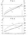
- la figure 1 représente l'évolution de la tension corrigée Uréf et du coefficient kréf d'une batterie de capacité nominale Cn = 93Ah lors de la charge rapide pour Tc = 23°C;
- la figure 2 est analogue à la figure 1 pour Tc = 0°C ;
- la figure 3 est analogue à la figure 1 pour Tc = -10°C ;
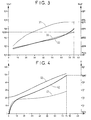
- la figure 4 montre la variation de la température interne et de la tension de la batterie, ainsi que la valeur correspondante de la tension corrigée Uc pour Tc = 23°C, lors d'une charge rapide à un régime de 1,5lc commencée à 21°C ;
- la figure 5 est analogue à la figure 4 pour une charge commencée à 0°C ;
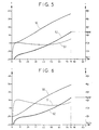
- la figure 6 est analogue à la figure 4 pour une charge commencée à -10°C ;
- la figure 7 est analogue à la figure 4 pour une charge commencée à -20°C ;
- la figure 8 est analogue à la figure 4 pour un régime de 0,75lc.
- FIG. 1 represents the evolution of the corrected voltage Uref and the kref coefficient of a battery of nominal capacity Cn = 93Ah during rapid charging for Tc = 23 ° C;
- Figure 2 is similar to Figure 1 for Tc = 0 ° C;
- Figure 3 is similar to Figure 1 for Tc = -10 ° C;
- figure 4 shows the variation of the internal temperature and the battery voltage, as well as the corresponding value of the corrected voltage Uc for Tc = 23 ° C, during a fast charge at a speed of 1.5lc started at 21 ° C;
- Figure 5 is similar to Figure 4 for a charge started at 0 ° C;
- Figure 6 is similar to Figure 4 for a charge started at -10 ° C;
- Figure 7 is similar to Figure 4 for a charge started at -20 ° C;
- Figure 8 is similar to Figure 4 for a speed of 0.75lc.
Sur les figures 1 à 3, la tension corrigée Uc en volt et la valeur du coefficient k en Volt/°C sont données en ordonnée, et en abscisse le taux de capacité chargé exprimé en % de la capacité nominale Cn de la batterie.In Figures 1 to 3, the corrected voltage Uc in volts and the value of coefficient k in Volt / ° C are given on the ordinate, and on the abscissa the rate of charged capacity expressed in% of the nominal capacity Cn of the battery.
Sur les figures 4 à 8, la température interne T en °C, la tension U et la tension corrigée Uc en Volt sont données en ordonnée, et en abscisse le taux de capacité chargé exprimé en % de la capacité nominale Cn de la batterie.In Figures 4 to 8, the internal temperature T in ° C, the voltage U and the corrected voltage Uc in Volt are given on the ordinate, and on the abscissa the rate of charged capacity expressed in% of the nominal capacity Cn of the battery.
A titre d'exemple, on applique le procédé selon l'invention à une batterie de cinq accumulateurs industriels nickel-métal hydrurable de type "sans maintenance". La batterie a une capacité nominale Cn de 93Ah et une tension moyenne en décharge de 6V.By way of example, the method according to the invention is applied to a battery of five industrial nickel-metal hydride accumulators of type "without maintenance ". The battery has a nominal capacity Cn of 93Ah and a voltage average discharge of 6V.
A partir d'un taux de charge initial nul, on effectue plusieurs charges de la batterie à un même régime, par exemple de 1,5lc, avec au moins deux températures initiales différentes, par exemple à 21°C et -10°C. Au cours de chaque charge, on mesure périodiquement la tension U et la température interne T de la batterie.From a zero initial charge rate, several charges of the battery at the same speed, for example 1.5lc, with at least two different initial temperatures, for example at 21 ° C and -10 ° C. During each load, the voltage U and the temperature are periodically measured internal battery T.
A partir des courbes précédemment établies, on reporte les valeurs de la tension U de la batterie en fonction de sa température interne T pour chaque taux de charge. On obtient une courbe U = f(T) qui est sensiblement linéaire et permet de calculer une pente kréf pour le taux de charge %Cn choisi. From the previously established curves, the values of the battery voltage U as a function of its internal temperature T for each rate dump. We obtain a curve U = f (T) which is substantially linear and allows to calculate a kref slope for the load rate% Cn chosen.
On trace la courbe U = f(T) pour différents taux de charge %Cn de la
batterie, et on reporte les valeurs de kréf obtenues pour tracer la courbe 11 de la
figure 1.We draw the curve U = f (T) for different load rates% Cn of the
battery, and the kref values obtained are plotted to plot
Au-delà d'un taux de charge de 55% de Cn, on observe que la valeur de kréf est sensiblement constante quel que soit le taux de charge de la batterie. Dans cet exemple, T est exprimé en °C et kréf est constant et vaut k = -0,015V/°C pour un taux de charge supérieur à 55% de Cn.Beyond a charge rate of 55% of Cn, we observe that the value of kref is substantially constant regardless of the battery charge rate. In this example, T is expressed in ° C and kref is constant and is equal to k = -0.015V / ° C for a charge rate greater than 55% of Cn.
Pour la batterie considérée, la formule permettant de calculer la tension
corrigée Uc selon la présente invention est donc la suivante :
A partir de l'une quelconque des courbes précédemment établies, on calcule la valeur de la tension de référence Uréf pour chaque taux de charge %CnFrom any of the previously established curves, we calculates the value of the reference voltage Uref for each load rate% Cn
Dans le cas représenté sur la figure 1, on a utilisé la courbe de charge
obtenue avec une température initiale de 21°C et on a pris comme température de
référence Tc une valeur de 23°C. On calcule donc Uréf selon la formule :
La valeur de kréf utilisée dans ce calcul est celle qui est donnée par la
courbe 11 de la figure 1 pour chaque état de charge. La courbe 12 est tracée avec
un coefficient kréf qui n'est pas constant dans le domaine des taux de charge
inférieurs ou égaux à 55% de Cn, et qui est constant et égal à k pour des taux de
charge supérieurs à 55%Cn.The kref value used in this calculation is that given by the
On constate que la tension de référence Uréf varie quasi-linéairement
avec l'état de charge, comme le montre la courbe 12 de la figure 1. La pente de la
courbe Uréf = f(%Cn) est suffisamment significative pour que l'on puisse l'utiliser
pour déterminer avec précision le taux de charge final souhaité.It can be seen that the reference voltage Uref varies almost linearly
with the state of charge, as shown in
On assimile la courbe 12 à une droite 13 dont on calcule l'équation :
L'utilisation de la valeur de kréf donnée par la courbe 11 dans ce calcul a
pour but de tracer cette droite sur un domaine suffisament large pour pouvoir en
établir l'équation avec précision. Le domaine d'exploitation de cette équation est
limité aux taux de charge supérieurs à 55% de Cn The use of the value of kref given by
En introduisant le taux de charge final souhaité dans cette équation,
comme par exemple un taux de charge de 75%, on peut calculer la tension
d'arrêt Us de la charge qui est dans ce cas de :
A titre d'illustration, on a représenté sur les figures 2 et 3 le calcul de Uréf en utilisant d'autres températures de référence Tc.By way of illustration, FIGS. 2 and 3 show the calculation of Uref using other reference temperatures Tc.
Dans le cas où Tc = 0°C, Uréf (courbe 22) est calculé par la formulet :
Dans le cas où Tc = -10°C, Uréf (courbe 32) est calculé par la formulet :
Il est bien entendu que lors du calcul de Uc au cours de la charge, on doit utiliser la même valeur de Tc que celle qui a servi à la détermination du seuil Us auquel on décide d'arrêter la charge.It is understood that when calculating Uc during charging, we must use the same value of Tc as that used to determine the Us threshold which we decide to stop charging.
La batterie de température initiale de 21°C (figure 4) est chargée à un régime de 1,5lc. On mesure périodiquement sa température interne (courbe 40) et sa tension (courbe 41). On voit bien que pour des accumulateurs de forte capacité, l'augmentation de la tension en charge est faible.The initial temperature battery of 21 ° C (Figure 4) is charged at a 1.5lc diet. Its internal temperature is periodically measured (curve 40) and its tension (curve 41). We can clearly see that for large accumulators capacity, the increase in load voltage is small.
On calcule immédiatement la tension corrigée Uc (courbe 42) en prenant
comme température de référence Tc = 23°C, selon la formule :
Dans ce calcul, le coefficient k est constant. La courbe de la tension corrigée Uc n'est significativement exploitable que dans le domaine des taux de charge supérieurs à 55% de Cn.In this calculation, the coefficient k is constant. The voltage curve corrected Uc can only be significantly exploited in the area of load greater than 55% of Cn.
La charge est arrêtée lorsque Uc est au moins égale à Us, c'est-à-dire au moins égale à 8,087V. On vérifie que le taux de charge atteint par la batterie est bien de 75% de Cn.The load is stopped when Uc is at least equal to Us, i.e. at less than 8.087V. We check that the charge rate reached by the battery is well 75% of Cn.
On reproduit la charge dans des conditions analogues à l'exemple 1, à l'exception du fait que la température initiale est de 0°C (figure 5).The charge is reproduced under conditions analogous to Example 1, at except that the initial temperature is 0 ° C (Figure 5).
On mesure périodiquement sa température interne (courbe 50) et sa tension (courbe 51) et on calcule la tension corrigée Uc (courbe 52) selon la formule : Uc = U + 0,015 (T - 23).Its internal temperature (curve 50) and its voltage (curve 51) and the corrected voltage Uc (curve 52) is calculated according to the formula: Uc = U + 0.015 (T - 23).
La charge est arrêtée lorsque Uc est au moins égale à 8,087V et le taux de charge atteint par la batterie est bien de 75% de Cn.Charging is stopped when Uc is at least 8.087V and the rate of charge reached by the battery is well 75% of Cn.
On reproduit la charge dans des conditions analogues à l'exemple 1, à l'exception du fait que la température initiale est de -10°C (figure 6).The charge is reproduced under conditions analogous to Example 1, at except that the initial temperature is -10 ° C (Figure 6).
On mesure périodiquement sa température interne (courbe 60) et sa tension (courbe 61) et on calcule la tension corrigée Uc (courbe 62) selon la formule: Uc = U + 0,015 (T - 23).Its internal temperature (curve 60) and its voltage (curve 61) and the corrected voltage Uc (curve 62) is calculated according to the formula: Uc = U + 0.015 (T - 23).
La charge est arrêtée lorsque Uc est au moins égale à 8,087V et le taux de charge atteint par la batterie est bien de 75% de Cn.Charging is stopped when Uc is at least 8.087V and the rate of charge reached by the battery is well 75% of Cn.
On reproduit la charge dans des conditions analogues à l'exemple 1, à l'exception du fait que la température initiale est de -20°C (figure 7).The charge is reproduced under conditions analogous to Example 1, at except that the initial temperature is -20 ° C (Figure 7).
On mesure périodiquement sa température interne (courbe 50) et sa tension (courbe 51) et on calcule la tension corrigée Uc (courbe 52) selon la formule : Uc = U + 0,015 (T - 23). On voit bien que pour des accumulateurs de forte capacité, l'échauffement est important.Its internal temperature (curve 50) and its voltage (curve 51) and the corrected voltage Uc (curve 52) is calculated according to the formula: Uc = U + 0.015 (T - 23). We can see that for accumulators of high capacity, heating is important.
La charge est arrêtée lorsque Uc est au moins égale à 8,087V et le taux de charge atteint par la batterie est bien de 75% de Cn. Charging is stopped when Uc is at least 8.087V and the rate of charge reached by the battery is well 75% of Cn.
On reproduit la charge dans des conditions analogues à l'exemple 1, à l'exception du fait que le régime est de 0,75lc (figure 8).The charge is reproduced under conditions analogous to Example 1, at except for the fact that the speed is 0.75lc (figure 8).
Comme précédemment, on mesure périodiquement la température
interne T (courbe 80) et la tension U (courbe 81) de la batterie. On calcule la
tension corrigée Uc (courbe 82) selon la formule :
Pour un même taux de charge final, le seuil de tension Us varie selon le régime de charge choisi de 0,70 volt par unité de courant exprimé en Ic, la température de référence Tc restant inchangée. Ici le passage d'un régime de 1,5lc à un régime de 0,75lc conduit à abaisser le seuil Us de 0,525V, soit de passer de 8,087V à 7,562V.For the same final charge rate, the voltage threshold Us varies according to the chosen charging regime of 0.70 volts per unit of current expressed in Ic, the reference temperature Tc remaining unchanged. Here the transition from a diet of 1.5lc at a speed of 0.75lc leads to lowering the Us threshold of 0.525V, i.e. to go from 8.087V to 7.562V.
La charge est donc arrêtée lorsque Uc est au moins égale à 7,562V et le taux de charge final atteint par la batterie est toujours de 75% de Cn.The charge is therefore stopped when Uc is at least equal to 7.562V and the final charge rate reached by the battery is always 75% of Cn.
On reproduit la charge dans des conditions analogues à l'exemple 3, à l'exception du fait que le régime est de 0,75lc.The charge is reproduced under conditions analogous to Example 3, at except for the fact that the diet is 0.75lc.
Comme précédemment, on mesure périodiquement sa température
interne et sa tension et on calcule la tension corrigée Uc selon la formule :
La charge est arrêtée lorsque Uc est au moins égale à 7,562V et le taux de charge atteint par la batterie est bien de 75% de Cn.Charging is stopped when Uc is at least 7.562V and the rate of charge reached by the battery is well 75% of Cn.
Claims (6)
- on compare Uc avec ledit seuil de tension Us et on arrête la charge lorsque Uc est au moins égale à Us.Process for controlling the rapid charge of an industrial alkaline electrolyte accumulator of the "maintenance-free" or "waterproof" type having a nominal capacity Cn, a voltage U and an internal temperature T, characterized in that the stopping of charging at a charge rate greater than 55% of Cn is carried out as follows:
- Uc is compared with said voltage threshold Us and the charge is stopped when Uc is at least equal to Us.
Applications Claiming Priority (2)
| Application Number | Priority Date | Filing Date | Title |
|---|---|---|---|
| FR9809914A FR2782417B1 (en) | 1998-08-13 | 1998-08-13 | METHOD FOR CONTROLLING THE FAST CHARGING OF AN ALKALINE ELECTROLYTE INDUSTRIAL BATTERY |
| FR9809914 | 1998-08-13 |
Publications (2)
| Publication Number | Publication Date |
|---|---|
| EP0980130A1 true EP0980130A1 (en) | 2000-02-16 |
| EP0980130B1 EP0980130B1 (en) | 2008-04-16 |
Family
ID=9529317
Family Applications (1)
| Application Number | Title | Priority Date | Filing Date |
|---|---|---|---|
| EP99401903A Expired - Lifetime EP0980130B1 (en) | 1998-08-13 | 1999-07-26 | Method for controlling the rapid charging of an alkaline electrolyte industrial accumulator |
Country Status (5)
| Country | Link |
|---|---|
| US (1) | US6094032A (en) |
| EP (1) | EP0980130B1 (en) |
| JP (1) | JP2000067927A (en) |
| DE (1) | DE69938522T2 (en) |
| FR (1) | FR2782417B1 (en) |
Cited By (4)
| Publication number | Priority date | Publication date | Assignee | Title |
|---|---|---|---|---|
| EP1328055A3 (en) * | 2002-01-10 | 2006-11-15 | Honda Giken Kogyo Kabushiki Kaisha | System for controlling charging of secondary battery |
| US7391183B2 (en) | 2002-01-17 | 2008-06-24 | Honda Giken Kogyo Kabushiki Kaisha | System for controlling charging of secondary battery |
| FR2950742A1 (en) * | 2009-09-29 | 2011-04-01 | Commissariat Energie Atomique | CHARGING METHOD AND METHOD FOR DETERMINING AN END-OF-CHARGE CRITERION OF A NICKEL BATTERY |
| RU2621694C2 (en) * | 2015-07-01 | 2017-06-07 | Российская Федерация, от имени которой выступает Министерство обороны Российской Федерации | Method for operating nickel-hydrogen accumulator batteries of aircraft electric power system |
Families Citing this family (3)
| Publication number | Priority date | Publication date | Assignee | Title |
|---|---|---|---|---|
| JP4340020B2 (en) * | 2001-04-10 | 2009-10-07 | パナソニック株式会社 | Charge control method for secondary battery for automatic guided vehicle |
| JP4161854B2 (en) * | 2003-09-02 | 2008-10-08 | ソニー株式会社 | Battery remaining capacity calculation method, battery remaining capacity calculation device, and battery remaining capacity calculation program |
| US9252463B2 (en) * | 2010-10-21 | 2016-02-02 | Chervon (Hk) Limited | Battery charging system having multiple charging modes |
Citations (3)
| Publication number | Priority date | Publication date | Assignee | Title |
|---|---|---|---|---|
| US5315228A (en) * | 1992-01-24 | 1994-05-24 | Compaq Computer Corp. | Battery charge monitor and fuel gauge |
| US5659239A (en) * | 1995-10-05 | 1997-08-19 | Saft | Method and apparatus for charging sealed nickel-cadmium batteries |
| US5703468A (en) * | 1995-03-17 | 1997-12-30 | Petrillo; Gino A. | Electrical charge control apparatus and method for photovoltaic energy conversion systems |
-
1998
- 1998-08-13 FR FR9809914A patent/FR2782417B1/en not_active Expired - Fee Related
-
1999
- 1999-07-26 DE DE69938522T patent/DE69938522T2/en not_active Expired - Lifetime
- 1999-07-26 EP EP99401903A patent/EP0980130B1/en not_active Expired - Lifetime
- 1999-08-10 JP JP11226548A patent/JP2000067927A/en active Pending
- 1999-08-12 US US09/373,238 patent/US6094032A/en not_active Expired - Lifetime
Patent Citations (3)
| Publication number | Priority date | Publication date | Assignee | Title |
|---|---|---|---|---|
| US5315228A (en) * | 1992-01-24 | 1994-05-24 | Compaq Computer Corp. | Battery charge monitor and fuel gauge |
| US5703468A (en) * | 1995-03-17 | 1997-12-30 | Petrillo; Gino A. | Electrical charge control apparatus and method for photovoltaic energy conversion systems |
| US5659239A (en) * | 1995-10-05 | 1997-08-19 | Saft | Method and apparatus for charging sealed nickel-cadmium batteries |
Cited By (9)
| Publication number | Priority date | Publication date | Assignee | Title |
|---|---|---|---|---|
| EP1328055A3 (en) * | 2002-01-10 | 2006-11-15 | Honda Giken Kogyo Kabushiki Kaisha | System for controlling charging of secondary battery |
| US7391183B2 (en) | 2002-01-17 | 2008-06-24 | Honda Giken Kogyo Kabushiki Kaisha | System for controlling charging of secondary battery |
| FR2950742A1 (en) * | 2009-09-29 | 2011-04-01 | Commissariat Energie Atomique | CHARGING METHOD AND METHOD FOR DETERMINING AN END-OF-CHARGE CRITERION OF A NICKEL BATTERY |
| WO2011039428A1 (en) * | 2009-09-29 | 2011-04-07 | Commissariat A L' Energie Atomique Et Aux Energies Alternatives | Method for charging a nickel battery and method for determining an end-of-charge criterion for a nickel battery |
| CN102640345A (en) * | 2009-09-29 | 2012-08-15 | 原子能和代替能源委员会 | Method for charging a nickel battery and method for determining an end-of-charge criterion for a nickel battery |
| US9166257B2 (en) | 2009-09-29 | 2015-10-20 | Commissariat A L'energie Atomique Et Aux Energies Alternatives | Method for charging and method for determining an end-of-charge criterion of a nickel-based battery |
| EP3349295A3 (en) * | 2009-09-29 | 2018-08-08 | Commissariat à l'Energie Atomique et aux Energies Alternatives | Method for determining an end-of-charge criterion of a nickel-based battery |
| RU2621694C2 (en) * | 2015-07-01 | 2017-06-07 | Российская Федерация, от имени которой выступает Министерство обороны Российской Федерации | Method for operating nickel-hydrogen accumulator batteries of aircraft electric power system |
| RU2621694C9 (en) * | 2015-07-01 | 2017-11-09 | Российская Федерация, от имени которой выступает Министерство обороны Российской Федерации | Method for operating nickel-hydrogen accumulator batteries of aircraft electric power system |
Also Published As
| Publication number | Publication date |
|---|---|
| US6094032A (en) | 2000-07-25 |
| DE69938522D1 (en) | 2008-05-29 |
| EP0980130B1 (en) | 2008-04-16 |
| JP2000067927A (en) | 2000-03-03 |
| FR2782417B1 (en) | 2000-09-15 |
| DE69938522T2 (en) | 2009-07-09 |
| FR2782417A1 (en) | 2000-02-18 |
Similar Documents
| Publication | Publication Date | Title |
|---|---|---|
| EP3191337B1 (en) | Method for managing the operating range of a battery | |
| BE1008147A6 (en) | Method for making the charge battery charger lead acid and interactive. | |
| EP2122379B1 (en) | Method for determining the discharge end threshold of a rechargeable battery | |
| EP0626746B1 (en) | Charge control method of a sealed nickel storage cell and charger therefor | |
| EP3237258B1 (en) | Method for energy management of a rechargeable traction battery of a hybrid vehicle | |
| EP2483962B1 (en) | Method for charging a nickel battery and method for determining an end-of-charge criterion for a nickel battery | |
| FR2803105A1 (en) | Fast charging method for rechargeable battery, involves performing fast charging using normal or restricted fast charge current depending on whether battery initial voltage is higher or lower than preset voltage | |
| FR2860301A1 (en) | APPARATUS FOR MONITORING THE CONDITION OF AN AUTOMOTIVE BATTERY | |
| WO2006003287A1 (en) | Method for managing a rechargeable battery storage | |
| EP0768745B1 (en) | Charging method for sealed nickel-cadmium batteries | |
| EP1766718A1 (en) | Method of charging a lithium-ion battery comprising a negative electrode | |
| WO2017050944A1 (en) | Method and device for determining a state-of-health indicator for a lithium battery | |
| EP2309615B1 (en) | System and method for managing the charge of a battery | |
| EP0980130B1 (en) | Method for controlling the rapid charging of an alkaline electrolyte industrial accumulator | |
| FR2949908A1 (en) | Electrochemical battery e.g. nickel-cadmium battery, monitoring method for portable computer, involves directly detecting abnormality within battery as path of harmful chemical reaction within battery or physical degradation of battery | |
| FR2636479A1 (en) | ULTRAPOID LOADING PROCESS FOR SEALED CADMIUM-NICKEL ACCUMULATOR | |
| EP1243935A1 (en) | Discharge control method for a battery of secundary electrochemical generators | |
| FR2907272A1 (en) | METHOD FOR MANAGING THE END OF DISCHARGE OF A RECHARGEABLE BATTERY | |
| EP3220471B1 (en) | Method of charging a battery of electrochemical accumulators and device for controlling the charging | |
| WO2021130068A1 (en) | Method for identifying the start of the acceleration of the degradation of the state of health of a pack of rechargeable batteries | |
| EP4101047A1 (en) | Method for pulse charging in voltage control mode with steps of variable amplitude | |
| FR2963997A1 (en) | Device for charging battery of e.g. electric or hybrid vehicle, on electric distribution network, has adjusting device formed of charge supervisor and diagnostic socket to adjust limit value of state of charge reaching end of charge | |
| FR2640817A1 (en) | Ultra-fast charger for electrical accumulator | |
| FR2798528A1 (en) | ELECTRIC CURRENT SUPPLY SYSTEM WITH MULTIPLE ENERGY ACCUMULATORS | |
| FR2722336A1 (en) | Process for maintaining battery charge at predetermined minimum level |
Legal Events
| Date | Code | Title | Description |
|---|---|---|---|
| PUAI | Public reference made under article 153(3) epc to a published international application that has entered the european phase |
Free format text: ORIGINAL CODE: 0009012 |
|
| AK | Designated contracting states |
Kind code of ref document: A1 Designated state(s): DE FR GB |
|
| AX | Request for extension of the european patent |
Free format text: AL;LT;LV;MK;RO;SI |
|
| 17P | Request for examination filed |
Effective date: 20000816 |
|
| AKX | Designation fees paid |
Free format text: DE FR GB |
|
| RAP1 | Party data changed (applicant data changed or rights of an application transferred) |
Owner name: SAFT FINANCE S.AE.R.L. |
|
| GRAP | Despatch of communication of intention to grant a patent |
Free format text: ORIGINAL CODE: EPIDOSNIGR1 |
|
| RIN1 | Information on inventor provided before grant (corrected) |
Inventor name: BARIAND, MARC Inventor name: BERLUREAU, THIERRY Inventor name: LISKA, JEAN-LOUIS |
|
| RAP1 | Party data changed (applicant data changed or rights of an application transferred) |
Owner name: SAFT FINANCE S.A.R.L. |
|
| RAP1 | Party data changed (applicant data changed or rights of an application transferred) |
Owner name: SAFT GROUPE SA |
|
| GRAS | Grant fee paid |
Free format text: ORIGINAL CODE: EPIDOSNIGR3 |
|
| GRAA | (expected) grant |
Free format text: ORIGINAL CODE: 0009210 |
|
| AK | Designated contracting states |
Kind code of ref document: B1 Designated state(s): DE FR GB |
|
| REF | Corresponds to: |
Ref document number: 69938522 Country of ref document: DE Date of ref document: 20080529 Kind code of ref document: P |
|
| PLBE | No opposition filed within time limit |
Free format text: ORIGINAL CODE: 0009261 |
|
| STAA | Information on the status of an ep patent application or granted ep patent |
Free format text: STATUS: NO OPPOSITION FILED WITHIN TIME LIMIT |
|
| 26N | No opposition filed |
Effective date: 20090119 |
|
| PGFP | Annual fee paid to national office [announced via postgrant information from national office to epo] |
Ref country code: GB Payment date: 20120629 Year of fee payment: 14 |
|
| GBPC | Gb: european patent ceased through non-payment of renewal fee |
Effective date: 20130726 |
|
| PG25 | Lapsed in a contracting state [announced via postgrant information from national office to epo] |
Ref country code: GB Free format text: LAPSE BECAUSE OF NON-PAYMENT OF DUE FEES Effective date: 20130726 |
|
| PGFP | Annual fee paid to national office [announced via postgrant information from national office to epo] |
Ref country code: DE Payment date: 20140724 Year of fee payment: 16 |
|
| REG | Reference to a national code |
Ref country code: DE Ref legal event code: R119 Ref document number: 69938522 Country of ref document: DE |
|
| PG25 | Lapsed in a contracting state [announced via postgrant information from national office to epo] |
Ref country code: DE Free format text: LAPSE BECAUSE OF NON-PAYMENT OF DUE FEES Effective date: 20160202 |
|
| REG | Reference to a national code |
Ref country code: FR Ref legal event code: PLFP Year of fee payment: 18 |
|
| PGFP | Annual fee paid to national office [announced via postgrant information from national office to epo] |
Ref country code: FR Payment date: 20160707 Year of fee payment: 18 |
|
| REG | Reference to a national code |
Ref country code: FR Ref legal event code: ST Effective date: 20180330 |
|
| PG25 | Lapsed in a contracting state [announced via postgrant information from national office to epo] |
Ref country code: FR Free format text: LAPSE BECAUSE OF NON-PAYMENT OF DUE FEES Effective date: 20170731 |