EP0979993B1 - A method of preselecting flashlamp voltages for assays - Google Patents
A method of preselecting flashlamp voltages for assays Download PDFInfo
- Publication number
- EP0979993B1 EP0979993B1 EP99306364A EP99306364A EP0979993B1 EP 0979993 B1 EP0979993 B1 EP 0979993B1 EP 99306364 A EP99306364 A EP 99306364A EP 99306364 A EP99306364 A EP 99306364A EP 0979993 B1 EP0979993 B1 EP 0979993B1
- Authority
- EP
- European Patent Office
- Prior art keywords
- lamp
- assays
- assay
- photoresponse
- intensity
- Prior art date
- Legal status (The legal status is an assumption and is not a legal conclusion. Google has not performed a legal analysis and makes no representation as to the accuracy of the status listed.)
- Expired - Lifetime
Links
- 238000003556 assay Methods 0.000 title claims abstract description 73
- 238000000034 method Methods 0.000 title claims abstract description 21
- 238000012360 testing method Methods 0.000 claims abstract description 13
- 239000003990 capacitor Substances 0.000 claims abstract description 12
- 230000003287 optical effect Effects 0.000 claims abstract description 12
- 230000003213 activating effect Effects 0.000 claims abstract description 5
- 238000010304 firing Methods 0.000 claims description 6
- 108010088751 Albumins Proteins 0.000 description 7
- 102000009027 Albumins Human genes 0.000 description 7
- 238000011088 calibration curve Methods 0.000 description 7
- 230000005855 radiation Effects 0.000 description 7
- 238000003366 endpoint assay Methods 0.000 description 5
- 238000005286 illumination Methods 0.000 description 5
- UFTFJSFQGQCHQW-UHFFFAOYSA-N triformin Chemical compound O=COCC(OC=O)COC=O UFTFJSFQGQCHQW-UHFFFAOYSA-N 0.000 description 4
- LWIHDJKSTIGBAC-UHFFFAOYSA-K potassium phosphate Substances [K+].[K+].[K+].[O-]P([O-])([O-])=O LWIHDJKSTIGBAC-UHFFFAOYSA-K 0.000 description 3
- QGZKDVFQNNGYKY-UHFFFAOYSA-N Ammonia Chemical compound N QGZKDVFQNNGYKY-UHFFFAOYSA-N 0.000 description 2
- -1 HDLC Chemical compound 0.000 description 2
- 239000001913 cellulose Substances 0.000 description 2
- 239000003153 chemical reaction reagent Substances 0.000 description 2
- HVYWMOMLDIMFJA-DPAQBDIFSA-N cholesterol Chemical compound C1C=C2C[C@@H](O)CC[C@]2(C)[C@@H]2[C@@H]1[C@@H]1CC[C@H]([C@H](C)CCCC(C)C)[C@@]1(C)CC2 HVYWMOMLDIMFJA-DPAQBDIFSA-N 0.000 description 2
- 239000006185 dispersion Substances 0.000 description 2
- 238000005259 measurement Methods 0.000 description 2
- 239000004382 Amylase Substances 0.000 description 1
- 102000013142 Amylases Human genes 0.000 description 1
- 108010065511 Amylases Proteins 0.000 description 1
- OYPRJOBELJOOCE-UHFFFAOYSA-N Calcium Chemical compound [Ca] OYPRJOBELJOOCE-UHFFFAOYSA-N 0.000 description 1
- CURLTUGMZLYLDI-UHFFFAOYSA-N Carbon dioxide Chemical compound O=C=O CURLTUGMZLYLDI-UHFFFAOYSA-N 0.000 description 1
- LFQSCWFLJHTTHZ-UHFFFAOYSA-N Ethanol Chemical compound CCO LFQSCWFLJHTTHZ-UHFFFAOYSA-N 0.000 description 1
- WQZGKKKJIJFFOK-GASJEMHNSA-N Glucose Natural products OC[C@H]1OC(O)[C@H](O)[C@@H](O)[C@@H]1O WQZGKKKJIJFFOK-GASJEMHNSA-N 0.000 description 1
- JVTAAEKCZFNVCJ-UHFFFAOYSA-M Lactate Chemical compound CC(O)C([O-])=O JVTAAEKCZFNVCJ-UHFFFAOYSA-M 0.000 description 1
- 102000004882 Lipase Human genes 0.000 description 1
- 108090001060 Lipase Proteins 0.000 description 1
- 239000004367 Lipase Substances 0.000 description 1
- WHXSMMKQMYFTQS-UHFFFAOYSA-N Lithium Chemical compound [Li] WHXSMMKQMYFTQS-UHFFFAOYSA-N 0.000 description 1
- FYYHWMGAXLPEAU-UHFFFAOYSA-N Magnesium Chemical compound [Mg] FYYHWMGAXLPEAU-UHFFFAOYSA-N 0.000 description 1
- OAICVXFJPJFONN-UHFFFAOYSA-N Phosphorus Chemical compound [P] OAICVXFJPJFONN-UHFFFAOYSA-N 0.000 description 1
- 238000008050 Total Bilirubin Reagent Methods 0.000 description 1
- LEHOTFFKMJEONL-UHFFFAOYSA-N Uric Acid Chemical compound N1C(=O)NC(=O)C2=C1NC(=O)N2 LEHOTFFKMJEONL-UHFFFAOYSA-N 0.000 description 1
- TVWHNULVHGKJHS-UHFFFAOYSA-N Uric acid Natural products N1C(=O)NC(=O)C2NC(=O)NC21 TVWHNULVHGKJHS-UHFFFAOYSA-N 0.000 description 1
- PNNCWTXUWKENPE-UHFFFAOYSA-N [N].NC(N)=O Chemical compound [N].NC(N)=O PNNCWTXUWKENPE-UHFFFAOYSA-N 0.000 description 1
- 229910021529 ammonia Inorganic materials 0.000 description 1
- 235000019418 amylase Nutrition 0.000 description 1
- 239000012491 analyte Substances 0.000 description 1
- WQZGKKKJIJFFOK-VFUOTHLCSA-N beta-D-glucose Chemical compound OC[C@H]1O[C@@H](O)[C@H](O)[C@@H](O)[C@@H]1O WQZGKKKJIJFFOK-VFUOTHLCSA-N 0.000 description 1
- BPYKTIZUTYGOLE-UHFFFAOYSA-N billirubin-IXalpha Natural products N1C(=O)C(C)=C(C=C)C1=CC1=C(C)C(CCC(O)=O)=C(CC2=C(C(C)=C(C=C3C(=C(C=C)C(=O)N3)C)N2)CCC(O)=O)N1 BPYKTIZUTYGOLE-UHFFFAOYSA-N 0.000 description 1
- 230000005540 biological transmission Effects 0.000 description 1
- 239000008280 blood Substances 0.000 description 1
- 210000004369 blood Anatomy 0.000 description 1
- 239000011575 calcium Substances 0.000 description 1
- 229910052791 calcium Inorganic materials 0.000 description 1
- 229910002092 carbon dioxide Inorganic materials 0.000 description 1
- 235000012000 cholesterol Nutrition 0.000 description 1
- 230000001276 controlling effect Effects 0.000 description 1
- 238000001514 detection method Methods 0.000 description 1
- 238000010586 diagram Methods 0.000 description 1
- 239000011521 glass Substances 0.000 description 1
- 239000008103 glucose Substances 0.000 description 1
- 238000001727 in vivo Methods 0.000 description 1
- 235000019421 lipase Nutrition 0.000 description 1
- 229910052744 lithium Inorganic materials 0.000 description 1
- 239000011777 magnesium Substances 0.000 description 1
- 229910052749 magnesium Inorganic materials 0.000 description 1
- 238000004519 manufacturing process Methods 0.000 description 1
- 238000012986 modification Methods 0.000 description 1
- 230000004048 modification Effects 0.000 description 1
- 229910052698 phosphorus Inorganic materials 0.000 description 1
- 239000011574 phosphorus Substances 0.000 description 1
- 238000012545 processing Methods 0.000 description 1
- 102000004169 proteins and genes Human genes 0.000 description 1
- 108090000623 proteins and genes Proteins 0.000 description 1
- 230000001105 regulatory effect Effects 0.000 description 1
- 238000011160 research Methods 0.000 description 1
- 150000003626 triacylglycerols Chemical class 0.000 description 1
- 229940116269 uric acid Drugs 0.000 description 1
Images


Classifications
-
- G—PHYSICS
- G01—MEASURING; TESTING
- G01J—MEASUREMENT OF INTENSITY, VELOCITY, SPECTRAL CONTENT, POLARISATION, PHASE OR PULSE CHARACTERISTICS OF INFRARED, VISIBLE OR ULTRAVIOLET LIGHT; COLORIMETRY; RADIATION PYROMETRY
- G01J3/00—Spectrometry; Spectrophotometry; Monochromators; Measuring colours
- G01J3/02—Details
- G01J3/10—Arrangements of light sources specially adapted for spectrometry or colorimetry
-
- G—PHYSICS
- G01—MEASURING; TESTING
- G01N—INVESTIGATING OR ANALYSING MATERIALS BY DETERMINING THEIR CHEMICAL OR PHYSICAL PROPERTIES
- G01N21/00—Investigating or analysing materials by the use of optical means, i.e. using sub-millimetre waves, infrared, visible or ultraviolet light
- G01N21/17—Systems in which incident light is modified in accordance with the properties of the material investigated
- G01N21/25—Colour; Spectral properties, i.e. comparison of effect of material on the light at two or more different wavelengths or wavelength bands
- G01N21/27—Colour; Spectral properties, i.e. comparison of effect of material on the light at two or more different wavelengths or wavelength bands using photo-electric detection ; circuits for computing concentration
- G01N21/274—Calibration, base line adjustment, drift correction
-
- G—PHYSICS
- G01—MEASURING; TESTING
- G01N—INVESTIGATING OR ANALYSING MATERIALS BY DETERMINING THEIR CHEMICAL OR PHYSICAL PROPERTIES
- G01N21/00—Investigating or analysing materials by the use of optical means, i.e. using sub-millimetre waves, infrared, visible or ultraviolet light
- G01N21/17—Systems in which incident light is modified in accordance with the properties of the material investigated
- G01N21/25—Colour; Spectral properties, i.e. comparison of effect of material on the light at two or more different wavelengths or wavelength bands
- G01N21/31—Investigating relative effect of material at wavelengths characteristic of specific elements or molecules, e.g. atomic absorption spectrometry
- G01N21/314—Investigating relative effect of material at wavelengths characteristic of specific elements or molecules, e.g. atomic absorption spectrometry with comparison of measurements at specific and non-specific wavelengths
- G01N2021/317—Special constructive features
- G01N2021/3174—Filter wheel
-
- G—PHYSICS
- G01—MEASURING; TESTING
- G01N—INVESTIGATING OR ANALYSING MATERIALS BY DETERMINING THEIR CHEMICAL OR PHYSICAL PROPERTIES
- G01N2201/00—Features of devices classified in G01N21/00
- G01N2201/06—Illumination; Optics
- G01N2201/069—Supply of sources
- G01N2201/0694—Microprocessor controlled supply
-
- G—PHYSICS
- G01—MEASURING; TESTING
- G01N—INVESTIGATING OR ANALYSING MATERIALS BY DETERMINING THEIR CHEMICAL OR PHYSICAL PROPERTIES
- G01N2201/00—Features of devices classified in G01N21/00
- G01N2201/12—Circuits of general importance; Signal processing
- G01N2201/124—Sensitivity
- G01N2201/1241—Multirange
-
- G—PHYSICS
- G01—MEASURING; TESTING
- G01N—INVESTIGATING OR ANALYSING MATERIALS BY DETERMINING THEIR CHEMICAL OR PHYSICAL PROPERTIES
- G01N2201/00—Features of devices classified in G01N21/00
- G01N2201/12—Circuits of general importance; Signal processing
- G01N2201/127—Calibration; base line adjustment; drift compensation
- G01N2201/12746—Calibration values determination
- G01N2201/12776—Automatic scaling up
Definitions
- This invention relates to a method for detecting optical changes in a test element using a lamp exposure, and the steps of selecting a voltage for the lamp to optimize the exposure level while extending the life of the lamp.
- analyzers that adjust a lamp intensity depending upon the sample transmission detected in real time at a detector, but not preselected before exposure, are shown in, e.g., Research Disclosure Publication No. 400001, dated August 1997.
- photoresponse efficiencies means, efficiencies dictated by the end-point photoresponsiveness of the chemistries used for a particular assay, and more specifically, the photoresponse that is determined from a plot of the photometric end-point density produced by the assay versus concentration of the analyte of that assay. In such plots, the steeper the curve, the more efficient is the photoresponse, and the less intense must be the illuminating device to obtain a satisfactory reading.
- the invention is particularly applicable to end-point assays.
- the reduction in voltage levels can be based not only upon the known system efficiencies of the illuminating device, but also upon predetermined photoresponse efficiencies of the pre-selected assays.
- the illuminating device is a flashlamp
- the system efficiency is determined by a) the energy of the flash lamp at the center wavelength used for the assay in question, b) the filter providing that center wavelength, and c) the photodetector used, which is preferably a photodiode
- the circuit for activating the lamp comprises a single firing capacitor and a variable output voltage converter.
- the invention is applicable regardless of the end-point assays to be tested and their photoresponse efficiencies, regardless of the type of illuminating device, photodetector, or lamp-activating circuit that is used, and regardless of which components of the illuminator and detector contribute, and how much, to the system efficiency at certain center wavelengths of exposure.
- the invention is preferably used with dried slide test elements premanufactured with the test reagents, currently available from Ortho-Clinical Diagnostics, Inc. under the trademark Vitros®, especially selected to assay for alcohol, glucose, conjugated and unconjugated bilirubin, total bilirubin, ammonia, albumin, protein, calcium, CO 2 , magnesium, HDLC, cholesterol, lithium, phosphorus , lactate, blood urea nitrogen, salicilate, uric acid, triglycerides, amylase, and lipase, to name a few. Some of these are two-measurement end-point assays, at two different wavelengths.
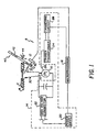
- the read station 8 of that analyzer, Fig. 1, preferably comprises an illuminator flashlamp 10, a photodetector 12, an activating circuit 14 for firing the lamp 10, a microprocessor 16 for controlling circuit 14 and processing signals from detector 12, and a support 18 for a slide test element E of the type described above.
- Circuit 14 in turn preferably comprises a power supply 20, a variable output high voltage converter 22, a trigger transformer 24 connected to lamp 10 by a firing pin 26, and a triggering circuit 28. All of the lamp 10, micro-processor 16, detector 12, power supply 20, voltage converter 22, trigger transformer 24, and triggering circuit 28 are conventional.
- converter 22 can be a Model PS450 Flashtube Power Supply available from EG&G ElectroOptics, Inc.
- Fig. 1 is particularly schematic in that rays 30 emanating from flashlamp 10 are shown as passing directly to element E, and reflected radiation 32 passing to detector 12 on a 90° - 45° arrangement. In fact, this is. only illustrative - the preferred mode of illumination is to first direct rays 30 into an integrating cavity that reflects diffuse radiation of no flash structure, onto element E.
- a representative useful example of such an integrating cavity with which flash lamp 10 can be associated is shown in the U.S. Patent No. 4,660,984 (MacDonald). The details of that patent are expressly incorporated herein by reference.
- Station 8 also preferably includes a filter wheel 40 with a plurality, and preferably eight of which only two are shown, filters 42.
- the wheel rotates, arrow 44, to position an appropriate filter in the path of the reflected radiation 32. (Auxiliary focusing lenses are not shown.)
- Any filter wheel can be used. However, highly preferred is that described and claimed in commonly-owned U.S. Application Serial No. 08/873,155, filed on June 11, 1997 (Attorney Docket No. CDS-141), entitled “Filter Wheel and Method Using Filters of Varying Thicknesses”. Such wheel and method feature the following:
- filters 42 each have a significantly different thickness, that is, t 1 ⁇ t 2 ⁇ t i (for i filters). Additionally, the thicknesses are selected peculiar to the center wavelength of the bandpass for that filter, so that the focal distance is the same for all the filters, obviating the need for lenses between rotor 40 and detector 12.
- the filters are most preferably eight (8) in number, selected to provide the assays of interest, a preferred selection of significantly different center wavelengths ⁇ c for their bandpass, as noted in Table I below.
- each filter has the noted preferred maximum bandpass, although these values are not critical to the mathematical relationship set forth hereinafter, so long as the filters remain narrow bandpass filters.
- wheel 40 is rotated so that only one or another of the plural filters therein (e.g., filter number 1, 2, - 8) is selected at any one time to intercept the beam that is converging through the filter.
- the selection is made based upon the detectable wavelength that is optimized for a given test element E, as is well known.
- a linearly-moveable frame can be used that is reciprocated back and forth, not shown.
- the optical system described for Fig. 1 has system efficiencies dictated by the flash energies of the lamp at the center wavelengths used for detection, the filters that provide such pass-through center wavelengths, and the photodetector.
- the resulting relative intensities detectable at the various center wavelengths of interest (340, 400, 460, 540, 600, 630, 670, and 680) are shown in Fig. 2. That is, the system is most efficient at 460 nm, and least efficient at 340 nm (assigned an arbitrary value of 1.0). Furthermore, at 460 nm the system is about 4.6 times as efficient as it is at 340 nm, measured by relative intensities.
- the next step is to assign the nominal full voltage value for the flashlamp to the weakest center wavelength - in this case, to the 340 nm center wavelength, Fig. 3.
- the nominal full voltage value for a nominal full intensity exposure is 650 volts. Because center wavelength 460 nm is about 4.6 times as efficient as 340 nm, the voltage to be applied to the flashlamp when using 460 nm center wavelength is determined as follows:
- Flash energy E for the flashlamp is determined from the equation.
- the voltages to be used for the other center wavelengths, adjusted to have a relative intensity equal to that of the 340 nm center wavelength, are determinable, and are the values shown in Fig. 3.
- the voltages that are applied to the other center wavelengths fall in between 305 and 650.
- the voltage applied to the flashlamp is scaled down a priori from the nominal full value, for a given assay to be tested, depending on which center wavelength is used - unless, of course, the center wavelength is 340 nm.
- the lamp's lifetime is extended as it is not always flashed at its maximum intensity.
- the fraction of the full nominal voltage to be used is further modified depending on the endpoint photoresponse efficiency of the particular assay. This is determined, Figs. 4 and 5, from the slope of a plot of the calibration curve of the particular assay, when compared to the extreme slope values illustrated here as being for triglyceride and for albumin.
- the most efficient photoresponsiveness is shown in the slope of the triglyceride plot, and the least is shown in the slope of the albumin plot, where "slope" for purposes of this invention is measured as the change in the absolute value of the density units measured over the entire dynamic range of the assay.
- the dynamic range for triglyceride is from 10 to 525 mg/dL.
- Full dynamic ranges as used in this application are those full ranges, based upon the analyzer and the reagent chemistries, that are published by an analyzer manufacturer as being reliable for use in a particular assay. It will be understood by those skilled in the art that these will vary from manufacturer to manufacturer, and over time.
- the change in density units from 10 to 525 is from about 0.3 to about 1.8, or a slope of 1.5 density units over the dynamic range.
- the least efficient photoresponse curve of albumin produces a slope of (0.9 - 0.5), or 0.4 density units, measured over its dynamic range of from 1 to 6 g/dL.
- multiplier fractions 1.0 for 0.4 slope, 0.5 for 1.5 slope and 3 ⁇ 4 for 0.95 slope, allow a transform plot to be drawn as in Fig. 6. Such a plot is used to determine the photoresponse efficiency multiplier fraction, based upon the slope of the calibration curve, for any assay.
- the CO 2 assay is measured at 340 center wavelength, and has a photoresponse curve that produces a negative density change of 1.88 at 5 mmol/L, to 1.12 at 40 mmol/L, which is its full dynamic range. Or, the absolute value of the slope of CO 2 is 0.76 density units. From the plot of Fig. 6, one can determine that the multiplier to be used for the photoresponse efficiency of CO 2 is about 0.84. That is, since CO 2 is measured at the center wavelength of 340 nm, Table III, the nominal full value of 650 volts, Fig. 3, is multiplied by 0.84 to produce a voltage of about 545 volts, and 545 volts is the reduced flashlamp intensity . that is used, preferably, to measure CO 2 .
Landscapes
- Physics & Mathematics (AREA)
- Spectroscopy & Molecular Physics (AREA)
- General Physics & Mathematics (AREA)
- Analytical Chemistry (AREA)
- General Health & Medical Sciences (AREA)
- Health & Medical Sciences (AREA)
- Life Sciences & Earth Sciences (AREA)
- Chemical & Material Sciences (AREA)
- Mathematical Physics (AREA)
- Biochemistry (AREA)
- Theoretical Computer Science (AREA)
- Engineering & Computer Science (AREA)
- Immunology (AREA)
- Pathology (AREA)
- Investigating Or Analysing Materials By Optical Means (AREA)
- Photometry And Measurement Of Optical Pulse Characteristics (AREA)
- Investigating Or Analysing Materials By The Use Of Chemical Reactions (AREA)
- Investigating, Analyzing Materials By Fluorescence Or Luminescence (AREA)
Abstract
Description
- This invention relates to a method for detecting optical changes in a test element using a lamp exposure, and the steps of selecting a voltage for the lamp to optimize the exposure level while extending the life of the lamp.
- It is known to provide feedback circuits in analyzers which alter in real time the output of illuminating devices, depending upon the level of signal detected at the detector. An example of such a system is shown in U.S. Patent No. 5,491,329, which uses the irradiation on in vivo tissue samples. Such tissue samples of course are not known in advance as to their photoresponse efficiencies. Furthermore, the reason for the feedback circuit in such a system is to allow the proper use of the gain on the photomultiplier tube used in the detector. Such a use is irrelevant to detectors using flash lamps and simple photodiodes.
- Yet another example of a real-time adjustment of the exposure device to reflect the system efficiencies of the optics is disclosed in U.S. Patent No. 5,029,245. In this case, LEDs are modified during sample examination so that the radiation outputted is "regulated in accordance with the intensity data supplied [in real time] by the detector and in such manner that the radiation intensity of that wavelength range, and thus the intensity of the output radiation, is constant," column 4, lines 10-14.
- Other examples of analyzers that adjust a lamp intensity depending upon the sample transmission detected in real time at a detector, but not preselected before exposure, are shown in, e.g., Research Disclosure Publication No. 400001, dated August 1997.
- Although real-time adjustments are useful, they have the disadvantage of requiring fairly complex and sensitive optical systems, given the wide range of possible outputs and the lack of a priori control of outputs. Also, real-time adjustments necessitate some delay in the assay while changes are made in response to the reading, compared to the time needed for assays that have predetermined settings selected in advance. Furthermore, those that adjust simply on the basis of an instantaneous result do not provide any adjustment based on known performances of that particular assay as a whole.
- Thus, there has been a need for a method of making energy level adjustments to illuminating devices in advance, for testing end-point assays selected from a list having known end-point photoresponse efficiencies, exposed in an optical system having a known system efficiency, without necessitating the complexities required for real-time adjustments.
- As used herein, "photoresponse efficiencies" means, efficiencies dictated by the end-point photoresponsiveness of the chemistries used for a particular assay, and more specifically, the photoresponse that is determined from a plot of the photometric end-point density produced by the assay versus concentration of the analyte of that assay. In such plots, the steeper the curve, the more efficient is the photoresponse, and the less intense must be the illuminating device to obtain a satisfactory reading.
- We have discovered a method of adjusting in advance the intensity of the illuminating device, based upon selecting an assay from a pre-selected list having known end-point photoresponse efficiencies and tested in an illuminating system having known system efficiencies that are a function of the center wavelength of exposure. The result is that the illumination intensity is optimal for that assay at that center wavelength, and specifically the power for that intensity is reduced for the more efficient assays and wavelengths, thus reducing the wear on and extending the life of, the illuminating device.
- More specifically, there is provided a method of detecting a change in optical density in a series of end-point test assays wherein said detectable changes in optical density are produced at varying efficiencies, the method comprising the steps of:
- a) selecting a test assay from said series, said selected assay having a known end-point photoresponse efficiency and a known filter center wavelength;
- b) providing a variable-intensity flash lamp illuminator comprising a lamp, a set of multiple filters with pre-selected center wavelengths assigned to particular assays, and a circuit for activating said lamp and comprising a capacitor, a power source, and a variable output voltage converter connected to said source and having its variable voltage output connected across said capacitor, said lamp and said filters providing a known level of system efficiency as a function of the center wavelength of the filter;
- c) providing a predetermined relationship between levels of illuminating intensities from said lamp at different wavelengths, in which the photoresponse efficiencies of said assays are inversely proportional to the lamp intensities and said intensities are proportional to the square of the voltages applied to said lamp;
- d) selecting from said relationship a voltage applied to said lamp, and hence an intensity of the lamp, that corresponds to said known photoresponse efficiency of the assay selected in step (a) and its system efficiency based upon the filter center wavelength for said assay; and
- e) thereafter exposing said assay to said selected illuminating intensity, so that less intensity is used for assays having either higher photoresponse efficiencies or center wavelengths with a higher system efficiency, than is used for worst-case efficiency assays.
-
- Because the photoresponse efficiencies are calculated in terms of densities, and not relative races of change, the invention is particularly applicable to end-point assays.
- Accordingly, it is an advantageous feature of the invention that voltage levels applied to a flashlamp illuminating device can be reduced in advance based upon known efficiencies of the assay to be illuminated, thereby extending the life of the flashlamp.
- It is a related advantageous feature of the invention that the reduction in voltage levels can be based not only upon the known system efficiencies of the illuminating device, but also upon predetermined photoresponse efficiencies of the pre-selected assays.
- Other advantageous features will become apparent upon reference to the following Detailed Description, when read in light of the attached drawings.
-
- Fig. 1 is a schematic circuit diagram of a preferred reading station used in the method of the invention;
- Fig. 2 is a plot of relative intensity of the illumination of the station shown in Fig. 1, as a function of the center-wavelength of the filter interposed in the path of the illuminating radiation, prior to the use of this invention;
- Fig. 3 is a plot of the voltage applied to the firing capacitor of the reading station of Fig. 1, when modified in accordance with one aspect of the invention;
- Figs. 4 and 5 are plots of two different photoresponse curves, specifically of reflection density versus concentration, Fig. 4 illustrating a maximum photoresponse efficiency example, and Fig. 5 illustrating a minimum photoresponse efficiency; and
- Fig. 6 is a plot of slopes obtained from the calibration curves of particular assays, against their photoresponse efficiency multiplier fractions, which vary from ½ to 1.
-
- The invention is described in connection with certain preferred embodiments, wherein certain end-point assays with characteristic response efficiencies are selected for testing, the illuminating device is a flashlamp, the system efficiency is determined by a) the energy of the flash lamp at the center wavelength used for the assay in question, b) the filter providing that center wavelength, and c) the photodetector used, which is preferably a photodiode; and the circuit for activating the lamp comprises a single firing capacitor and a variable output voltage converter. In addition, the invention is applicable regardless of the end-point assays to be tested and their photoresponse efficiencies, regardless of the type of illuminating device, photodetector, or lamp-activating circuit that is used, and regardless of which components of the illuminator and detector contribute, and how much, to the system efficiency at certain center wavelengths of exposure.
- Thus, the invention is preferably used with dried slide test elements premanufactured with the test reagents, currently available from Ortho-Clinical Diagnostics, Inc. under the trademark Vitros®, especially selected to assay for alcohol, glucose, conjugated and unconjugated bilirubin, total bilirubin, ammonia, albumin, protein, calcium, CO2, magnesium, HDLC, cholesterol, lithium, phosphorus , lactate, blood urea nitrogen, salicilate, uric acid, triglycerides, amylase, and lipase, to name a few. Some of these are two-measurement end-point assays, at two different wavelengths.
- These are preferably assayed by being exposed to illumination delivered and detected on a clinical analyzer that is otherwise conventional, except for the following:-
- The read station 8 of that analyzer, Fig. 1, preferably comprises an illuminator flashlamp 10, a photodetector 12, an activating circuit 14 for firing the lamp 10, a microprocessor 16 for controlling circuit 14 and processing signals from detector 12, and a support 18 for a slide test element E of the type described above. Circuit 14 in turn preferably comprises a power supply 20, a variable output high voltage converter 22, a trigger transformer 24 connected to lamp 10 by a firing pin 26, and a triggering circuit 28. All of the lamp 10, micro-processor 16, detector 12, power supply 20, voltage converter 22, trigger transformer 24, and triggering circuit 28 are conventional. For example, converter 22 can be a Model PS450 Flashtube Power Supply available from EG&G ElectroOptics, Inc.
- Fig. 1 is particularly schematic in that rays 30 emanating from flashlamp 10 are shown as passing directly to element E, and reflected radiation 32 passing to detector 12 on a 90° - 45° arrangement. In fact, this is. only illustrative - the preferred mode of illumination is to first direct rays 30 into an integrating cavity that reflects diffuse radiation of no flash structure, onto element E. A representative useful example of such an integrating cavity with which flash lamp 10 can be associated is shown in the U.S. Patent No. 4,660,984 (MacDonald). The details of that patent are expressly incorporated herein by reference.
- Station 8 also preferably includes a filter wheel 40 with a plurality, and preferably eight of which only two are shown, filters 42. The wheel rotates, arrow 44, to position an appropriate filter in the path of the reflected radiation 32. (Auxiliary focusing lenses are not shown.)
- Any filter wheel can be used. However, highly preferred is that described and claimed in commonly-owned U.S. Application Serial No. 08/873,155, filed on June 11, 1997 (Attorney Docket No. CDS-141), entitled "Filter Wheel and Method Using Filters of Varying Thicknesses". Such wheel and method feature the following:
- To eliminated the need for lenses altogether between wheel 40 and detector 12 filters 42 (and any others distributed about the circumference of the rotor 40 substantially equidistant from its axis) each have a significantly different thickness, that is, t1 ≠ t2 ≠ ti (for i filters). Additionally, the thicknesses are selected peculiar to the center wavelength of the bandpass for that filter, so that the focal distance is the same for all the filters, obviating the need for lenses between rotor 40 and detector 12.
- The filters are most preferably eight (8) in number, selected to provide the assays of interest, a preferred selection of significantly different center wavelengths λc for their bandpass, as noted in Table I below. In addition, each filter has the noted preferred maximum bandpass, although these values are not critical to the mathematical relationship set forth hereinafter, so long as the filters remain narrow bandpass filters.
Filter Number λc (µm) Maximum Bandpass (nm) 1 0.340 26 2 0.400 12 3 0.460 22 4 0.540 11 5 0.600 12 6 0.630 13 7 0.670 9 8 0.680 13 - Given these values for λc, the thicknesses for each filter are selected in accordance with the following predetermined formula:wherein t = thickness of the filter in mm, S = change in focal length in mm due to the presence of the filter (a constant value, λc = the center wavelength in microns of the bandpass of the filter, and B1, B2, B3, C1, C2, and C3 are constants of the Sellmeier Dispersion Formula, available from glass manufacturers.
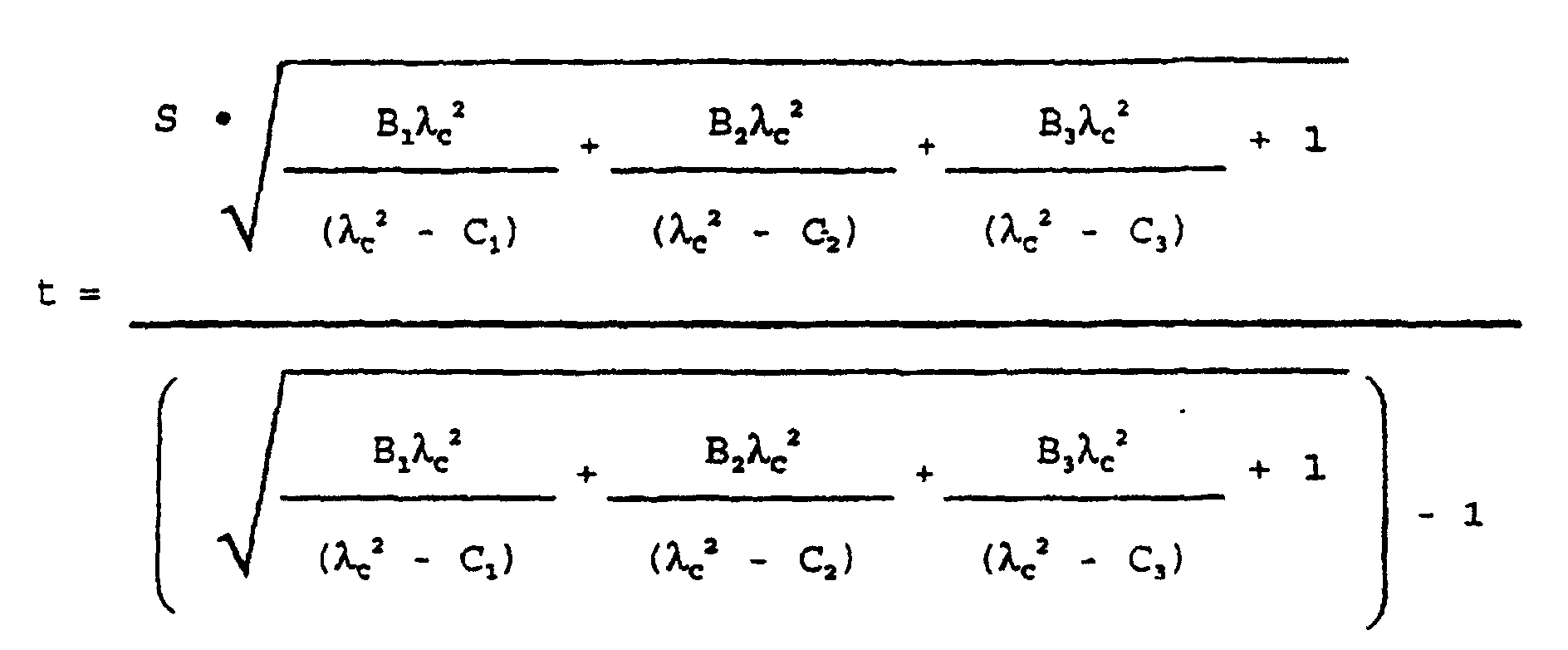
- The above equation is derived from the Sellmeier Dispersion Formula, and Snell's Law simplified for use with small angles of incidence, namely S = (t/n)(n-1), wherein S + t are as defined above, and n is the index of refraction. Based on this equation, the filters have the preferred and unique thicknesses, for their given λc, set forth in Table II:
Filter Number Thickness (in mm) 1 6.096 2 7.093 3 7.296 4 7.276 5 7.194 6 7.145 7 7.075 8 7.057 - (The optical assembly of Fig. 1 with these filters is adjusted to provide an F number of 3.8.)
- It will be appreciated that, for other values of λc and "d", thicknesses different from those of Table I can be selected.
- In use, wheel 40 is rotated so that only one or another of the plural filters therein (e.g., filter number 1, 2, - 8) is selected at any one time to intercept the beam that is converging through the filter. The selection, of course, is made based upon the detectable wavelength that is optimized for a given test element E, as is well known.
- It is not necessary that the detecting station use a filter wheel to move the various filters into position. Instead, a linearly-moveable frame can be used that is reciprocated back and forth, not shown.
- As noted above, the optical system described for Fig. 1 has system efficiencies dictated by the flash energies of the lamp at the center wavelengths used for detection, the filters that provide such pass-through center wavelengths, and the photodetector. For a preferred optical system, the resulting relative intensities detectable at the various center wavelengths of interest (340, 400, 460, 540, 600, 630, 670, and 680) are shown in Fig. 2. That is, the system is most efficient at 460 nm, and least efficient at 340 nm (assigned an arbitrary value of 1.0). Furthermore, at 460 nm the system is about 4.6 times as efficient as it is at 340 nm, measured by relative intensities.
- (It will be appreciated by those skilled in the art that these efficiencies and how they compare to each other will vary as the components of the optical system, and the choice of center wavelengths, vary. Whatever system is selected, the raw, relative intensities need only be measured at the center wavelengths of choice.)
- Given the plot of Fig. 2, the next step is to assign the nominal full voltage value for the flashlamp to the weakest center wavelength - in this case, to the 340 nm center wavelength, Fig. 3. For a preferred flashlamp in question, the nominal full voltage value for a nominal full intensity exposure, is 650 volts. Because center wavelength 460 nm is about 4.6 times as efficient as 340 nm, the voltage to be applied to the flashlamp when using 460 nm center wavelength is determined as follows:
- Flash energy E for the flashlamp is determined from the equation.
- E = ½CV2, where C is the capacitance of the capacitor of Fig. 1 and V is the voltage V+ applied to the flashlamp. Since a preferred capacitance value is 1 µF, then E340 for the 650 volts applied at 340 nm (Fig. 2), becomes,
- It is already apparent from Fig. 2 that a 460 nm center wavelength measurement needs a flash energy that is 1/4.6 that of the 340 nm center wavelength. Or, the flash energy,
- In like manner, the voltages to be used for the other center wavelengths, adjusted to have a relative intensity equal to that of the 340 nm center wavelength, are determinable, and are the values shown in Fig. 3.
- Thus, the voltages that are applied to the other center wavelengths fall in between 305 and 650.
- Of the particular assays tested above, the center wavelengths listed in Table III are particularly useful:

- In this fashion, the voltage applied to the flashlamp is scaled down a priori from the nominal full value, for a given assay to be tested, depending on which center wavelength is used - unless, of course, the center wavelength is 340 nm. Hence, the lamp's lifetime is extended as it is not always flashed at its maximum intensity.
- Still further, however, the fraction of the full nominal voltage to be used, whether equal to 1.0 x 650 volts in the case of the 340 nm, 305 volts in the case of 460 nm, or something in-between, is further modified depending on the endpoint photoresponse efficiency of the particular assay. This is determined, Figs. 4 and 5, from the slope of a plot of the calibration curve of the particular assay, when compared to the extreme slope values illustrated here as being for triglyceride and for albumin. That is, the most efficient photoresponsiveness is shown in the slope of the triglyceride plot, and the least is shown in the slope of the albumin plot, where "slope" for purposes of this invention is measured as the change in the absolute value of the density units measured over the entire dynamic range of the assay.
- Thus, in Fig. 4, the dynamic range for triglyceride is from 10 to 525 mg/dL. ("Full dynamic ranges" as used in this application are those full ranges, based upon the analyzer and the reagent chemistries, that are published by an analyzer manufacturer as being reliable for use in a particular assay. It will be understood by those skilled in the art that these will vary from manufacturer to manufacturer, and over time.) As is seen from Fig. 4, the change in density units from 10 to 525 is from about 0.3 to about 1.8, or a slope of 1.5 density units over the dynamic range.
- In contrast, the least efficient photoresponse curve of albumin produces a slope of (0.9 - 0.5), or 0.4 density units, measured over its dynamic range of from 1 to 6 g/dL.
- Thus, a full value of lamp intensity is given to albumin's exposure, taking into account, however, that its reading at 630 nm has already reduced its voltage requirement, Fig. 3, to 475 volts instead of the full nominal value of 650 volts. That is, because albumin's photoresponse efficiency is the least efficient, its flashlamp voltage value of 475 volts is not further reduced.
- However, all other assays are further reduced from the values shown in Fig. 3. More specifically, the exposure intensity shown in Fig. 3 is reduced by one-half if the slope of the calibration curve, over the full dynamic range, is as steep as that of Fig. 4, namely 1.5 density units. (This assumes that the assay in question has sufficient inherent precision such that a 50% reduction in illumination intensity will not render the assay so imprecise as to be outside acceptable clinical bounds.)
- It is believed that all other assays listed in Table III have slopes between that of triglyceride and albumin, and are accordingly assigned a multiplier fraction in between ½ and 1. Thus, an assay whose slope is 0.95, or half-way between 0.4 and 1.5, is assigned a multiplier fraction of .75. Thus, if such an assay should use a center wavelength of 600 nm, the intensity to be applied to the flashlamp is only 3/4 that used for 460 volts. Solving for Vu in (Vu)2/(460)2 = 0.75, one gets a voltage of 398 for such a case. As one skilled will realize, in no case should the lamp voltage be reduced below the minimum operating voltage.
- These values of multiplier fractions of 1.0 for 0.4 slope, 0.5 for 1.5 slope and ¾ for 0.95 slope, allow a transform plot to be drawn as in Fig. 6. Such a plot is used to determine the photoresponse efficiency multiplier fraction, based upon the slope of the calibration curve, for any assay.
- Stated another way, the CO2 assay is measured at 340 center wavelength, and has a photoresponse curve that produces a negative density change of 1.88 at 5 mmol/L, to 1.12 at 40 mmol/L, which is its full dynamic range. Or, the absolute value of the slope of CO2 is 0.76 density units. From the plot of Fig. 6, one can determine that the multiplier to be used for the photoresponse efficiency of CO2 is about 0.84. That is, since CO2 is measured at the center wavelength of 340 nm, Table III, the nominal full value of 650 volts, Fig. 3, is multiplied by 0.84 to produce a voltage of about 545 volts, and 545 volts is the reduced flashlamp intensity . that is used, preferably, to measure CO2.
- It is, of course, possible that an assay could produce a slope in its calibration curve that exceeds 1.5. In that case, whatever its value is as an extension of the plot of Fig. 6 into the next, upper left quadrant, shown as a dotted line, the appropriate multiplier fraction below 0.5 can be determined.
- Likewise, should the.slope of a calibration curve be less than 0.4, the plot of Fig. 6 can be extended, not shown, into the lower right quadrant to produce a multiplier fraction greater than 1.0. There is a limit, however, since much less than 0.4 produces a calibration curve having a too-low signal-to-noise ratio, as is well-known.
- The invention disclosed herein may be practiced in the absence of any element which is not specifically disclosed herein.
- The invention has been described in detail with particular reference to preferred embodiments thereof, but it will be understood that variations and modifications can be effected within the scope of the claims.
Claims (10)
- A method of detecting a change in optical density in a series of end-point test assays wherein said detectable changes in optical density are produced at varying efficiencies, the method comprising the steps of:a) selecting a test assay from said series, said selected assay having a known end-point photoresponse efficiency and a known filter center wavelength;b) providing a variable-intensity flash lamp illuminator comprising a lamp. (10), a set of multiple filters (42) with pre-selected center wavelengths assigned to particular assays, and a circuit (14) for activating said lamp (10) and comprising a capacitor, a power source (20), and a variable output voltage converter (22) connected to said source (20) and having its variable voltage output connected across said capacitor, said lamp (10) and said filters (42) providing a known level of system efficiency as a function of the center wavelength of the filter (42);c) providing a predetermined relationship between levels of illuminating intensities from said lamp (10) at different wavelengths, in which the photoresponse efficiencies of said assays are inversely proportional to the lamp intensities and said intensities are proportional to the square of the voltages applied.to said lamp (10);d) selecting from said relationship a voltage applied to said lamp (10), and hence an intensity of the lamp (10), that corresponds to said known photoresponse efficiency of the assay selected in step (a) and its system efficiency based upon the filter center wavelength for said assay; ande) thereafter exposing said assay to said selected illuminating intensity, so that less intensity is used for assays having either higher photoresponse efficiencies or center wavelengths with a higher system efficiency, or both, than is used for worst-case efficiency assays.
- A method as defined in claim 1, and further including the step of detecting light reflected from said assay using a photodiode (12).
- A method as defined in claim 1, wherein said predetermined relationship comprises the step of assigning a nominal full level of illuminating intensity, IF, and hence voltage applied to said lamp, to assays having a center wavelength of 340 nm, and reduced levels of illuminating intensities to assays having center wavelengths above said 340 nm.
- A method as defined in claim 3, wherein said predetermined relationship is further defined by assigning said nominal full level of illuminating intensity, and hence applied voltage only to 340 nm wavelength assays having a density versus concentration photoresponse curve that is no steeper than a curve having a slope of an absolute value of 0.4 density units over the entire dynamic range of said assay.
- A method as defined in claim 4, wherein said assigned level of illuminating intensity based upon the center wavelength is multiplied by a fraction less than 1.0 for a selected assay having a photoresponse curve whose slope is steeper than said slope of an absolute value of 0.4 density units over the entire dynamic range of said assay.
- A method as defined in claim 5, wherein a selected assay having a photoresponse curve with a slope of an absolute value of 1.5 density units over the entire dynamic range of said assay, is exposed to said assigned level of illuminating intensity based upon center wavelength, multiplied by the fraction one-half.
- A method as defined in claim 3, wherein for assays having a center wavelength of 460 nm, the predetermined relationship comprises the step of assigning the value of 0.5 x IF of illuminating intensity, and hence a value of 0.7 x the applied voltage.
- A method as defined in claim 7, and further including the steps of assigning a level of illuminating intensity to assays having center wavelengths that are other than 340 and 460 nm, that is between said nominal full level and said 0.7 of the full level of said voltage.
- A method as defined in claim 8, wherein for said nominal full level of illuminating intensity, the voltage applied to said flashlamp (10) is a voltage that is about 650 volts.
- A method as defined in claim 1 wherein said step b) comprises providing a flashlamp (10) as said illuminator and providing in said circuit (14), a firing capacitor and a variable output voltage converter having its variable voltage output connected across said capacitor, so that the voltage selected by said step d) is applied to the firing capacitor to fire the flashlamp (10) at said selected intensity.
Applications Claiming Priority (2)
| Application Number | Priority Date | Filing Date | Title |
|---|---|---|---|
| US9636198P | 1998-08-13 | 1998-08-13 | |
| US96361P | 1998-08-13 |
Publications (3)
| Publication Number | Publication Date |
|---|---|
| EP0979993A2 EP0979993A2 (en) | 2000-02-16 |
| EP0979993A3 EP0979993A3 (en) | 2000-03-29 |
| EP0979993B1 true EP0979993B1 (en) | 2003-05-02 |
Family
ID=22257009
Family Applications (1)
| Application Number | Title | Priority Date | Filing Date |
|---|---|---|---|
| EP99306364A Expired - Lifetime EP0979993B1 (en) | 1998-08-13 | 1999-08-12 | A method of preselecting flashlamp voltages for assays |
Country Status (5)
| Country | Link |
|---|---|
| US (1) | US6310337B1 (en) |
| EP (1) | EP0979993B1 (en) |
| JP (1) | JP2000155094A (en) |
| AT (1) | ATE239222T1 (en) |
| DE (1) | DE69907338T2 (en) |
Family Cites Families (9)
| Publication number | Priority date | Publication date | Assignee | Title |
|---|---|---|---|---|
| GB1486505A (en) | 1974-06-04 | 1977-09-21 | Compur Werk Gmbh & Co | Handheld photoelectric appliance for testing liquids |
| US4024428A (en) | 1975-05-19 | 1977-05-17 | Optical Associates, Incorporated | Radiation-sensitive control circuit for driving lamp at various power levels |
| CA1201606A (en) | 1983-01-27 | 1986-03-11 | Donald L. Kramer | Photometric device |
| US4643571A (en) | 1984-09-14 | 1987-02-17 | The Perkin-Elmer Corporation | Current control system for spectrophotometers |
| JPS63252239A (en) | 1987-04-09 | 1988-10-19 | Sumitomo Electric Ind Ltd | reflective oximeter |
| FI77736C (en) | 1987-06-25 | 1989-04-10 | Valtion Teknillinen | FOERFARANDE FOER REGLERING AV STRAOLKAELLA OCH REGLERBAR STRAOLKAELLA. |
| US5281540A (en) * | 1988-08-02 | 1994-01-25 | Abbott Laboratories | Test array for performing assays |
| DE4013586C2 (en) | 1990-04-27 | 1994-08-18 | Suzuki Motor Co | Device for the detection of immunological agglutination |
| JP3474612B2 (en) | 1993-12-03 | 2003-12-08 | 浜松ホトニクス株式会社 | Photodetector |
-
1999
- 1999-08-03 US US09/366,247 patent/US6310337B1/en not_active Expired - Fee Related
- 1999-08-12 EP EP99306364A patent/EP0979993B1/en not_active Expired - Lifetime
- 1999-08-12 DE DE69907338T patent/DE69907338T2/en not_active Expired - Fee Related
- 1999-08-12 AT AT99306364T patent/ATE239222T1/en not_active IP Right Cessation
- 1999-08-13 JP JP11229095A patent/JP2000155094A/en active Pending
Also Published As
| Publication number | Publication date |
|---|---|
| DE69907338T2 (en) | 2004-02-19 |
| EP0979993A2 (en) | 2000-02-16 |
| DE69907338D1 (en) | 2003-06-05 |
| ATE239222T1 (en) | 2003-05-15 |
| JP2000155094A (en) | 2000-06-06 |
| EP0979993A3 (en) | 2000-03-29 |
| US6310337B1 (en) | 2001-10-30 |
Similar Documents
| Publication | Publication Date | Title |
|---|---|---|
| US4171909A (en) | Apparatus for measuring light intensities | |
| US6999173B2 (en) | Method and apparatus for ratio fluorometry | |
| US4755058A (en) | Device and method for measuring light diffusely reflected from a nonuniform specimen | |
| CA2018858C (en) | Optical read head for immunoassay instrument | |
| US6075613A (en) | Optical scanner calibration device | |
| CA1226453A (en) | Device and method for measuring light diffusely reflected from a nonuniform specimen | |
| FI77736B (en) | FOERFARANDE FOER REGLERING AV STRAOLKAELLA OCH REGLERBAR STRAOLKAELLA. | |
| US4977325A (en) | Optical read system and immunoassay method | |
| CN1521495A (en) | Multi-Wavelength Readhead for Analyte Determination in Body Fluids | |
| AU2818997A (en) | Method and device for measuring reflected optical radiation | |
| US20040021077A1 (en) | High speed analyzer using near infrared radiation transmitted through thick samples of optically dense materials | |
| JPS63175744A (en) | Optical absorption analyzer | |
| EP0806662B1 (en) | Apparatus and method for determination of urine color | |
| CN118225769B (en) | Optical system of dry biochemical analyzer | |
| US20060066850A1 (en) | Light measuring device, biochemical analyzer, biochemical analysis method, and spectrophotometer | |
| JP2001515744A (en) | Measuring device for measuring autofluorescence of the cornea of the eye | |
| US6310337B1 (en) | Method of preselecting flashlamp voltages for assays | |
| US5194916A (en) | Fluorescence spectrophotometer | |
| US5903346A (en) | Analysis system | |
| JP2002521656A (en) | Method for testing the function of a spectrometer and a spectrometer having a fault detection device | |
| JPH03274427A (en) | Spectroscope | |
| EP0081947A1 (en) | Method and apparatus for normalizing radiometric measurements | |
| JPH11508053A (en) | Analysis system | |
| JP2761215B2 (en) | Fluorescent color measurement device | |
| JP2000310592A (en) | Optical measuring device |
Legal Events
| Date | Code | Title | Description |
|---|---|---|---|
| PUAI | Public reference made under article 153(3) epc to a published international application that has entered the european phase |
Free format text: ORIGINAL CODE: 0009012 |
|
| PUAL | Search report despatched |
Free format text: ORIGINAL CODE: 0009013 |
|
| AK | Designated contracting states |
Kind code of ref document: A2 Designated state(s): AT BE CH CY DE DK ES FI FR GB GR IE IT LI LU MC NL PT SE |
|
| AX | Request for extension of the european patent |
Free format text: AL;LT;LV;MK;RO;SI |
|
| AK | Designated contracting states |
Kind code of ref document: A3 Designated state(s): AT BE CH CY DE DK ES FI FR GB GR IE IT LI LU MC NL PT SE |
|
| AX | Request for extension of the european patent |
Free format text: AL;LT;LV;MK;RO;SI |
|
| 17P | Request for examination filed |
Effective date: 20000904 |
|
| AKX | Designation fees paid |
Free format text: AT BE CH CY DE DK ES FI FR GB GR IE IT LI LU MC NL PT SE |
|
| 17Q | First examination report despatched |
Effective date: 20020320 |
|
| GRAH | Despatch of communication of intention to grant a patent |
Free format text: ORIGINAL CODE: EPIDOS IGRA |
|
| GRAH | Despatch of communication of intention to grant a patent |
Free format text: ORIGINAL CODE: EPIDOS IGRA |
|
| GRAA | (expected) grant |
Free format text: ORIGINAL CODE: 0009210 |
|
| AK | Designated contracting states |
Designated state(s): AT BE CH CY DE DK ES FI FR GB GR IE IT LI LU MC NL PT SE |
|
| PG25 | Lapsed in a contracting state [announced via postgrant information from national office to epo] |
Ref country code: NL Free format text: LAPSE BECAUSE OF FAILURE TO SUBMIT A TRANSLATION OF THE DESCRIPTION OR TO PAY THE FEE WITHIN THE PRESCRIBED TIME-LIMIT Effective date: 20030502 Ref country code: FI Free format text: LAPSE BECAUSE OF FAILURE TO SUBMIT A TRANSLATION OF THE DESCRIPTION OR TO PAY THE FEE WITHIN THE PRESCRIBED TIME-LIMIT Effective date: 20030502 Ref country code: BE Free format text: LAPSE BECAUSE OF FAILURE TO SUBMIT A TRANSLATION OF THE DESCRIPTION OR TO PAY THE FEE WITHIN THE PRESCRIBED TIME-LIMIT Effective date: 20030502 Ref country code: AT Free format text: LAPSE BECAUSE OF FAILURE TO SUBMIT A TRANSLATION OF THE DESCRIPTION OR TO PAY THE FEE WITHIN THE PRESCRIBED TIME-LIMIT Effective date: 20030502 |
|
| REG | Reference to a national code |
Ref country code: GB Ref legal event code: FG4D |
|
| REG | Reference to a national code |
Ref country code: CH Ref legal event code: EP |
|
| REF | Corresponds to: |
Ref document number: 69907338 Country of ref document: DE Date of ref document: 20030605 Kind code of ref document: P |
|
| REG | Reference to a national code |
Ref country code: IE Ref legal event code: FG4D |
|
| REG | Reference to a national code |
Ref country code: CH Ref legal event code: NV Representative=s name: E. BLUM & CO. PATENTANWAELTE |
|
| PG25 | Lapsed in a contracting state [announced via postgrant information from national office to epo] |
Ref country code: SE Free format text: LAPSE BECAUSE OF FAILURE TO SUBMIT A TRANSLATION OF THE DESCRIPTION OR TO PAY THE FEE WITHIN THE PRESCRIBED TIME-LIMIT Effective date: 20030802 Ref country code: GR Free format text: LAPSE BECAUSE OF FAILURE TO SUBMIT A TRANSLATION OF THE DESCRIPTION OR TO PAY THE FEE WITHIN THE PRESCRIBED TIME-LIMIT Effective date: 20030802 Ref country code: DK Free format text: LAPSE BECAUSE OF FAILURE TO SUBMIT A TRANSLATION OF THE DESCRIPTION OR TO PAY THE FEE WITHIN THE PRESCRIBED TIME-LIMIT Effective date: 20030802 |
|
| PG25 | Lapsed in a contracting state [announced via postgrant information from national office to epo] |
Ref country code: PT Free format text: LAPSE BECAUSE OF FAILURE TO SUBMIT A TRANSLATION OF THE DESCRIPTION OR TO PAY THE FEE WITHIN THE PRESCRIBED TIME-LIMIT Effective date: 20030804 |
|
| PG25 | Lapsed in a contracting state [announced via postgrant information from national office to epo] |
Ref country code: LU Free format text: LAPSE BECAUSE OF NON-PAYMENT OF DUE FEES Effective date: 20030812 Ref country code: IE Free format text: LAPSE BECAUSE OF NON-PAYMENT OF DUE FEES Effective date: 20030812 Ref country code: CY Free format text: LAPSE BECAUSE OF FAILURE TO SUBMIT A TRANSLATION OF THE DESCRIPTION OR TO PAY THE FEE WITHIN THE PRESCRIBED TIME-LIMIT Effective date: 20030812 |
|
| PG25 | Lapsed in a contracting state [announced via postgrant information from national office to epo] |
Ref country code: ES Free format text: LAPSE BECAUSE OF FAILURE TO SUBMIT A TRANSLATION OF THE DESCRIPTION OR TO PAY THE FEE WITHIN THE PRESCRIBED TIME-LIMIT Effective date: 20030813 |
|
| PG25 | Lapsed in a contracting state [announced via postgrant information from national office to epo] |
Ref country code: MC Free format text: LAPSE BECAUSE OF NON-PAYMENT OF DUE FEES Effective date: 20030831 |
|
| NLV1 | Nl: lapsed or annulled due to failure to fulfill the requirements of art. 29p and 29m of the patents act | ||
| ET | Fr: translation filed | ||
| PLBE | No opposition filed within time limit |
Free format text: ORIGINAL CODE: 0009261 |
|
| STAA | Information on the status of an ep patent application or granted ep patent |
Free format text: STATUS: NO OPPOSITION FILED WITHIN TIME LIMIT |
|
| 26N | No opposition filed |
Effective date: 20040203 |
|
| REG | Reference to a national code |
Ref country code: IE Ref legal event code: MM4A |
|
| PG25 | Lapsed in a contracting state [announced via postgrant information from national office to epo] |
Ref country code: IT Free format text: LAPSE BECAUSE OF NON-PAYMENT OF DUE FEES Effective date: 20050812 |
|
| PGFP | Annual fee paid to national office [announced via postgrant information from national office to epo] |
Ref country code: DE Payment date: 20070809 Year of fee payment: 9 |
|
| REG | Reference to a national code |
Ref country code: CH Ref legal event code: PFA Owner name: ORTHO-CLINICAL DIAGNOSTICS, INC. Free format text: ORTHO-CLINICAL DIAGNOSTICS, INC.#100 INDIGO CREEK DRIVE#ROCHESTER, NY 14626-5101 (US) -TRANSFER TO- ORTHO-CLINICAL DIAGNOSTICS, INC.#100 INDIGO CREEK DRIVE#ROCHESTER, NY 14626-5101 (US) |
|
| PGFP | Annual fee paid to national office [announced via postgrant information from national office to epo] |
Ref country code: CH Payment date: 20070815 Year of fee payment: 9 |
|
| PGFP | Annual fee paid to national office [announced via postgrant information from national office to epo] |
Ref country code: GB Payment date: 20070809 Year of fee payment: 9 |
|
| PGFP | Annual fee paid to national office [announced via postgrant information from national office to epo] |
Ref country code: FR Payment date: 20070808 Year of fee payment: 9 |
|
| REG | Reference to a national code |
Ref country code: CH Ref legal event code: PL |
|
| GBPC | Gb: european patent ceased through non-payment of renewal fee |
Effective date: 20080812 |
|
| REG | Reference to a national code |
Ref country code: FR Ref legal event code: ST Effective date: 20090430 |
|
| PG25 | Lapsed in a contracting state [announced via postgrant information from national office to epo] |
Ref country code: LI Free format text: LAPSE BECAUSE OF NON-PAYMENT OF DUE FEES Effective date: 20080831 Ref country code: CH Free format text: LAPSE BECAUSE OF NON-PAYMENT OF DUE FEES Effective date: 20080831 |
|
| PG25 | Lapsed in a contracting state [announced via postgrant information from national office to epo] |
Ref country code: FR Free format text: LAPSE BECAUSE OF NON-PAYMENT OF DUE FEES Effective date: 20080901 Ref country code: DE Free format text: LAPSE BECAUSE OF NON-PAYMENT OF DUE FEES Effective date: 20090303 |
|
| PG25 | Lapsed in a contracting state [announced via postgrant information from national office to epo] |
Ref country code: GB Free format text: LAPSE BECAUSE OF NON-PAYMENT OF DUE FEES Effective date: 20080812 |