EP0979948A1 - Fan blade assembly of a ceiling fan - Google Patents
Fan blade assembly of a ceiling fan Download PDFInfo
- Publication number
- EP0979948A1 EP0979948A1 EP98306361A EP98306361A EP0979948A1 EP 0979948 A1 EP0979948 A1 EP 0979948A1 EP 98306361 A EP98306361 A EP 98306361A EP 98306361 A EP98306361 A EP 98306361A EP 0979948 A1 EP0979948 A1 EP 0979948A1
- Authority
- EP
- European Patent Office
- Prior art keywords
- surface wall
- engaging
- mounting
- blade assembly
- blade
- Prior art date
- Legal status (The legal status is an assumption and is not a legal conclusion. Google has not performed a legal analysis and makes no representation as to the accuracy of the status listed.)
- Granted
Links
- 230000008878 coupling Effects 0.000 claims abstract description 14
- 238000010168 coupling process Methods 0.000 claims abstract description 14
- 238000005859 coupling reaction Methods 0.000 claims abstract description 14
- 230000002093 peripheral effect Effects 0.000 claims abstract description 12
- 238000010276 construction Methods 0.000 description 2
- 230000000717 retained effect Effects 0.000 description 2
- 230000037431 insertion Effects 0.000 description 1
- 238000003780 insertion Methods 0.000 description 1
- 230000014759 maintenance of location Effects 0.000 description 1
- 239000007769 metal material Substances 0.000 description 1
Images


Classifications
-
- F—MECHANICAL ENGINEERING; LIGHTING; HEATING; WEAPONS; BLASTING
- F04—POSITIVE - DISPLACEMENT MACHINES FOR LIQUIDS; PUMPS FOR LIQUIDS OR ELASTIC FLUIDS
- F04D—NON-POSITIVE-DISPLACEMENT PUMPS
- F04D25/00—Pumping installations or systems
- F04D25/02—Units comprising pumps and their driving means
- F04D25/08—Units comprising pumps and their driving means the working fluid being air, e.g. for ventilation
- F04D25/088—Ceiling fans
-
- F—MECHANICAL ENGINEERING; LIGHTING; HEATING; WEAPONS; BLASTING
- F04—POSITIVE - DISPLACEMENT MACHINES FOR LIQUIDS; PUMPS FOR LIQUIDS OR ELASTIC FLUIDS
- F04D—NON-POSITIVE-DISPLACEMENT PUMPS
- F04D29/00—Details, component parts, or accessories
- F04D29/26—Rotors specially for elastic fluids
- F04D29/32—Rotors specially for elastic fluids for axial flow pumps
- F04D29/34—Blade mountings
Definitions
- This invention relates to a fan blade assembly of a ceiling fan for mounting on a rotor of a ceiling fan, more particularly to a fan blade assembly which can retain a blade member on a mounting arm effectively and firmly.
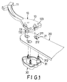
- a conventional fan blade assembly is shown to include a mounting arm 10 with one end 11 secured on a rotor (not shown) and the other end formed as a plate-like blade mounting end 13 which has a plurality of through holes 133 and a plurality of engaging posts 131 extending downwardly from the blade mounting end 13 adjacent to the through holes 133.
- a blade member 20 is formed with a plurality of mounting holes 21, each confined by an inner peripheral wall with a constricted portion to divide the mounting hole 21 into a notch portion 211 and a bore portion 212.
- each engaging post 131 can be pressed into the bore portion 212 of the respective mounting hole 21, and can then be moved into the notch portion 211 via the constricted portion such that a retaining portion 132 thereof rests on a bottom side of the blade member 20.
- a cap member 30 has a plurality of resilient engaging plugs 31 with retaining portions 312. Each engaging plug 31 is inserted into and is fitted snugly in the bore portion 212 of the respective mounting hole 21 such that the retaining portion 312 passes through the through hole 133 for retention on the mounting end 13.
- the blade member 20 can be mounted on the mounting arm 10.
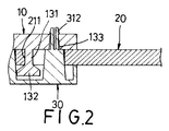
- the mounting arm 10 and the cap member 30 are made of metal material and are not produced with high precision, it is difficult to assemble the engaging plugs 31 into the mounting holes 21 and the through holes 133. In addition, a clearance will be caused in each mounting hole 21 between the engaging post 131 and the respective engaging plug 31, thereby resulting in unsteady engagement of the blade member 20 on the mounting arm 10.
- the object of the present invention is to provide a fan blade assembly which can retain a blade member on a mounting arm effectively and firmly.
- a fan blade assembly includes a mounting arm with a mounting end which is formed with a plurality of engaging posts.
- a blade member has a plurality of mounting holes, each having a larger bore portion and a smaller notch portion divided by a constricted portion.
- a plurality of elastomeric coupling members are sleeved securely on the engaging posts, and have shanks and radial outward peripheral flanges. Each coupling member is fitted snugly in the notch portion by passing the shank thereinto after the peripheral flange has been brought to pass through the bore portion to rest on one side of the blade member.
- a cap member has a plurality of engaging plugs.
- each engaging plug is inserted into and is fitted snugly in the bore portion of the respective mounting hole in such a manner that a guiding portion thereof will gradually be brought to abut against the constricted portion.
- each engaging plug is further split to form a resilient portion for facilitating insertion of the engaging plug into the bore portion of the respective mounting hole.
- the first preferred embodiment of a fan blade assembly is shown to comprise a mounting arm 40 which has a connecting end portion 41 adapted for coupling with a rotor of a ceiling fan (not shown), and a plate-like blade mounting end portion 43 with first and second surface walls 431,432 and a plurality of engaging posts 44 protruding downwardly from the second surface wall 432 in a longitudinal direction.
- Each engaging post 44 includes an upper section 441, a lower section 443, and a narrow neck section 442 formed between the upper and lower sections 441,443.
- a blade member 50 has a connecting end which has a third surface wall 501 confronting the second surface wall 432, and an opposite fourth surface wall 502.
- the connecting end further has a plurality of mounting holes 51, each of which is confined by an inner peripheral wall 511 with a constricted portion 511a to divide the mounting hole 51 into a notch portion 513 and a bore portion 512 of a dimension larger than that of the notch portion 513.
- a plurality of elastomeric coupling members 45 are mounted to the connecting end of the blade member 50.
- Each coupling member 45 has a through hole 453 so that the corresponding one of the engaging posts 44 is inserted into and is retainingly engaged in the through hole 453 in such a manner that the lower section 443 hooks on a bottom side of the coupling member 45.
- each coupling member 45 includes a head 451 and a shank 452 which extends downwardly from the head 451 and which has a radial outward peripheral flange 452a.
- a cap member 60 has an upper fifth surface wall 601 which confronts the fourth surface wall 502 and which has a plurality of annular engaging plugs 61 extending upwardly in the longitudinal direction from the fifth surface wall 502.
- Each engaging plug 61 is formed with a distal engaging portion 612, and a proximate engaging portion 613 proximate to the fifth wall surface 601 and provided with an inclined guiding portion 611.
- the engaging plug 61 is split to form a resilient portion 62 at a position opposite to the guiding portion 611.
- the resilient portion 62 has a radially and outwardly extending retaining portion 621 on a top end thereof so as to hook on the third surface wall 501 immediately after the engaging plug 61 has been press-fitted in the bore portion 512 of the respective mounting hole 51 against a biasing action of the retaining portion 621.
- the coupling members 45 are fitted snugly in the notch portions 513, respectively, by passing the shanks 452 thereinto after the peripheral flanges 452a have been brought to pass downwardly through the bore portion 512 to rest on the fourth surface wall 502 of the blade member 50. Subsequently, the engaging plugs 61 are brought to be inserted upwardly into and fitted snugly in the bore portions 512, respectively, so that the guiding portions 611 abut gradually against the constricted portions 511a.
- each engaging plug 61 can be inserted easily into the bore portion 512 of the respective mounting hole 51 due to the provision of the resilient portion 62.
- the engaging plug 61 and the coupling member 45 can be engaged together tightly, thereby preventing the creation of a clearance therebetween in the respective mounting hole 51.
- the blade member 50 can be retained securely on the mounting arm 40.
- the noise due to vibrations when the ceiling fan rotates can be eliminated by virtue of the coupling members 45.
- cap member 60 can be decorated to enhance the aesthetic appeal of the ceiling fan.
- the second preferred embodiment of the fan blade assembly is shown to have a construction similar to that of the first preferred embodiment, except that the first surface wall 431' of the mounting arm 40' is under the second surface wall 432'. That is, the engaging posts 44' extend upwardly from the second surface wall 432'. Likewise, the engaging plugs 61' of the cap member 60'extend downwardly from the fifth surface wall 601' so as to retain the cap member 60' above the blade mounting end portion 43' in a manner similar to that mentioned hereinabove.
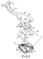
- Figs. 7 and 8 show the third preferred embodiment of this invention, wherein, in addition to the components of the first preferred embodiment, the cap member 70 further has a resilient dog member 72 which extends upwardly in the longitudinal direction from the fifth surface wall 701 among the engaging plugs 71.
- the dog member 72 has a length longer than that of the engaging plugs 71, and a hook end portion 721 so as to hook on the first surface wall 431 immediately after the dog member 72 passes snugly though a through hole 52 in the blade member 50 and a through hole 46 in the blade mounting end portion 43 against a biasing action of the hook end portion 721. As such, the blade member 50 is firmly retained on the mounting arm 40.
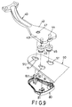
- the cap member 80 of the fourth preferred embodiment has a dog member 82 to replace one of the engaging plugs 81. Since the dog member 82 is similar to the dog member 72 in Fig. 7, a detailed description of the construction thereof will be omitted herein.
- the blade mounting end portion 43 is formed with a through hole 47 near one of the engaging posts 44 so that the hook end portion 821 of the dog member 82 can pass through the bore portion 512 of one of the mounting holes 51 and the through hole 47 to hook on the first surface wall 431.
Abstract
Description
- This invention relates to a fan blade assembly of a ceiling fan for mounting on a rotor of a ceiling fan, more particularly to a fan blade assembly which can retain a blade member on a mounting arm effectively and firmly.
- Referring to Figs. 1 and 2, a conventional fan blade assembly is shown to include a
mounting arm 10 with oneend 11 secured on a rotor (not shown) and the other end formed as a plate-likeblade mounting end 13 which has a plurality of throughholes 133 and a plurality ofengaging posts 131 extending downwardly from theblade mounting end 13 adjacent to the throughholes 133. Ablade member 20 is formed with a plurality of mountingholes 21, each confined by an inner peripheral wall with a constricted portion to divide themounting hole 21 into anotch portion 211 and abore portion 212. As such, eachengaging post 131 can be pressed into thebore portion 212 of therespective mounting hole 21, and can then be moved into thenotch portion 211 via the constricted portion such that aretaining portion 132 thereof rests on a bottom side of theblade member 20. Acap member 30 has a plurality of resilientengaging plugs 31 with retainingportions 312. Eachengaging plug 31 is inserted into and is fitted snugly in thebore portion 212 of therespective mounting hole 21 such that theretaining portion 312 passes through the throughhole 133 for retention on themounting end 13. Thus, theblade member 20 can be mounted on themounting arm 10. - Since the
mounting arm 10 and thecap member 30 are made of metal material and are not produced with high precision, it is difficult to assemble theengaging plugs 31 into themounting holes 21 and the throughholes 133. In addition, a clearance will be caused in eachmounting hole 21 between theengaging post 131 and the respectiveengaging plug 31, thereby resulting in unsteady engagement of theblade member 20 on themounting arm 10. - The object of the present invention is to provide a fan blade assembly which can retain a blade member on a mounting arm effectively and firmly.
- According to this invention, a fan blade assembly includes a mounting arm with a mounting end which is formed with a plurality of engaging posts. A blade member has a plurality of mounting holes, each having a larger bore portion and a smaller notch portion divided by a constricted portion. A plurality of elastomeric coupling members are sleeved securely on the engaging posts, and have shanks and radial outward peripheral flanges. Each coupling member is fitted snugly in the notch portion by passing the shank thereinto after the peripheral flange has been brought to pass through the bore portion to rest on one side of the blade member. A cap member has a plurality of engaging plugs. Each engaging plug is inserted into and is fitted snugly in the bore portion of the respective mounting hole in such a manner that a guiding portion thereof will gradually be brought to abut against the constricted portion. Preferably, each engaging plug is further split to form a resilient portion for facilitating insertion of the engaging plug into the bore portion of the respective mounting hole.
- Other features and advantages of the present invention will become apparent in the following detailed description of the preferred embodiments of the invention, with reference to the accompanying drawings, in which:
- Fig. 1 is an exploded view showing a portion of a conventional fan blade assembly of a ceiling fan;
- Fig. 2 is a sectional view of Fig. 1;
- Fig. 3 is an exploded view of a first preferred embodiment of a portion of a fan blade assembly according to this invention;
- Fig. 4 is a sectional view of a portion of the fan blade assembly according to the first preferred embodiment;
- Fig. 5 is an exploded view of a second preferred embodiment of a portion of a fan blade assembly according to this invention;
- Fig. 6 is a sectional view of a portion of the fan blade assembly according to the second preferred embodiment;
- Fig. 7 is an exploded view of a third preferred embodiment of a portion of a fan blade assembly according to this invention;
- Fig. 8 is a sectional view of a portion of the fan blade assembly according to the third preferred embodiment; and
- Fig. 9 is an exploded view of a fourth preferred embodiment of a portion of a fan blade assembly according to this invention.
-
- Before the present invention is described in greater detail, it should be noted that same reference numerals have been used to denote like elements throughout the specification
- Referring to Figs. 3 and 4, the first preferred embodiment of a fan blade assembly according to the present invention is shown to comprise a
mounting arm 40 which has a connectingend portion 41 adapted for coupling with a rotor of a ceiling fan (not shown), and a plate-like blademounting end portion 43 with first and second surface walls 431,432 and a plurality ofengaging posts 44 protruding downwardly from thesecond surface wall 432 in a longitudinal direction. Eachengaging post 44 includes anupper section 441, alower section 443, and anarrow neck section 442 formed between the upper and lower sections 441,443. - A
blade member 50 has a connecting end which has athird surface wall 501 confronting thesecond surface wall 432, and an oppositefourth surface wall 502. The connecting end further has a plurality of mountingholes 51, each of which is confined by an innerperipheral wall 511 with aconstricted portion 511a to divide themounting hole 51 into anotch portion 513 and abore portion 512 of a dimension larger than that of thenotch portion 513. - A plurality of
elastomeric coupling members 45 are mounted to the connecting end of theblade member 50. Eachcoupling member 45 has a through hole 453 so that the corresponding one of theengaging posts 44 is inserted into and is retainingly engaged in the through hole 453 in such a manner that thelower section 443 hooks on a bottom side of thecoupling member 45. In addition, eachcoupling member 45 includes ahead 451 and ashank 452 which extends downwardly from thehead 451 and which has a radial outward peripheral flange 452a. - A
cap member 60 has an upperfifth surface wall 601 which confronts thefourth surface wall 502 and which has a plurality of annularengaging plugs 61 extending upwardly in the longitudinal direction from thefifth surface wall 502. Eachengaging plug 61 is formed with a distalengaging portion 612, and a proximateengaging portion 613 proximate to thefifth wall surface 601 and provided with an inclined guidingportion 611. In addition, theengaging plug 61 is split to form aresilient portion 62 at a position opposite to the guidingportion 611. Theresilient portion 62 has a radially and outwardly extending retainingportion 621 on a top end thereof so as to hook on thethird surface wall 501 immediately after theengaging plug 61 has been press-fitted in thebore portion 512 of therespective mounting hole 51 against a biasing action of theretaining portion 621. - In assembly, after being sleeved retainingly on the
engaging posts 44, thecoupling members 45 are fitted snugly in thenotch portions 513, respectively, by passing theshanks 452 thereinto after the peripheral flanges 452a have been brought to pass downwardly through thebore portion 512 to rest on thefourth surface wall 502 of theblade member 50. Subsequently, theengaging plugs 61 are brought to be inserted upwardly into and fitted snugly in thebore portions 512, respectively, so that the guidingportions 611 abut gradually against theconstricted portions 511a. - As such, each
engaging plug 61 can be inserted easily into thebore portion 512 of therespective mounting hole 51 due to the provision of theresilient portion 62. In addition, theengaging plug 61 and thecoupling member 45 can be engaged together tightly, thereby preventing the creation of a clearance therebetween in therespective mounting hole 51. Thus, theblade member 50 can be retained securely on themounting arm 40. Also, the noise due to vibrations when the ceiling fan rotates can be eliminated by virtue of thecoupling members 45. - It is noted that the
cap member 60 can be decorated to enhance the aesthetic appeal of the ceiling fan. - Referring to Figs. 5 and 6, the second preferred embodiment of the fan blade assembly according to this invention is shown to have a construction similar to that of the first preferred embodiment, except that the first surface wall 431' of the mounting arm 40' is under the second surface wall 432'. That is, the engaging posts 44' extend upwardly from the second surface wall 432'. Likewise, the engaging plugs 61' of the cap member 60'extend downwardly from the fifth surface wall 601' so as to retain the cap member 60' above the blade mounting end portion 43' in a manner similar to that mentioned hereinabove.
- Figs. 7 and 8 show the third preferred embodiment of this invention, wherein, in addition to the components of the first preferred embodiment, the
cap member 70 further has aresilient dog member 72 which extends upwardly in the longitudinal direction from thefifth surface wall 701 among theengaging plugs 71. Thedog member 72 has a length longer than that of theengaging plugs 71, and ahook end portion 721 so as to hook on thefirst surface wall 431 immediately after thedog member 72 passes snugly though a throughhole 52 in theblade member 50 and a throughhole 46 in the blademounting end portion 43 against a biasing action of thehook end portion 721. As such, theblade member 50 is firmly retained on themounting arm 40. - Alternatively, as shown in Fig. 9, as compared with the first preferred embodiment, the
cap member 80 of the fourth preferred embodiment has adog member 82 to replace one of theengaging plugs 81. Since thedog member 82 is similar to thedog member 72 in Fig. 7, a detailed description of the construction thereof will be omitted herein. The blademounting end portion 43 is formed with a throughhole 47 near one of theengaging posts 44 so that thehook end portion 821 of thedog member 82 can pass through thebore portion 512 of one of themounting holes 51 and the throughhole 47 to hook on thefirst surface wall 431.
Claims (3)
- A fan blade assembly adapted to be mounted on a rotor of a ceiling fan, said fan blade assembly including a mounting arm (40,40') having a plate-like blade mounting end portion (43,43') with a first surface wall (431,431'), a second surface wall (432,432'), and a plurality of engaging posts (44,44') protruding from said second surface wall (432,432') in a longitudinal direction;a blade member (50) having a connecting end which has a third surface wall (501) confronting said second surface wall (432,432') and a fourth surface wall (502) opposite to said third surface wall (501); anda cap member (60,60',70,80) having a fifth surface wall (601,601',701) confronting said fourth surface wall (502);
further characterized by:said connecting end further having a plurality of inner peripheral walls (511) that confine respectively a plurality of mounting holes (51), each of said inner peripheral walls (511) having a constricted portion (511a) to divide a corresponding one of said mounting holes (51) into a notch portion (513) and a bore portion (512) of a dimension larger than that of said notch portion (513);a plurality of elastomeric coupling members (45,45'), each of which has a through hole (453) formed therethrough such that a corresponding one of said engaging posts (44) is inserted into and is retainingly engaged in said through hole (453), each of said coupling members (45) including a shank (452), and a radial outward peripheral flange (452a) projecting from said shank (452), and being fitted snugly in said notch portion (513) by passing said shank (452) thereinto after said peripheral flange (452a) has been brought to pass through said bore portion (512) to rest on said fourth surface wall (502) of said blade member (50); andsaid cap member (60,60',70,80) further having a plurality of annular engaging plugs (61,61',71,81), each of which extends in the longitudinal direction from said fifth surface wall (601,601',701) to form a distal engaging portion (612) and a proximate engaging portion (613) proximate to said fifth surface wall (601,601',701), said distal engaging portion (612) having a guiding portion (611) at a position such that when said engaging plug (61,61',71,81) is brought to be inserted into and fitted snugly in said bore portion (512) of a respective one of said mounting holes (51), said guiding portion (611) will abut gradually against said constricted portion (511a). - The fan blade assembly as claimed in Claim 1, characterized in that each of said engaging plugs (61,61',71,81) is split to form a resilient portion (62) with a radially and outwardly extending retaining portion (621) which hooks on said third surface wall (501) of said blade member (50) immediately after each of said engaging plugs (61,61',71,81) has been press-fitted in said bore portion (512) of the respective one of said mounting holes (51) against a biasing action of said retaining portion (621).
- The fan blade assembly as claimed in Claim 1 or 2, further characterized by a resilient dog member (72,82) formed on said cap member (70,80) and extending in the longitudinal direction from said fifth surface wall (701), said dog member (72,82) having a length longer than that of said engaging plugs (71,81), and a hook end portion (721,821) which hooks on said first surface wall (431) immediately after said dog member (72,82) has been brought to pass snugly though said blade member (50) and said blade mounting end portion (43) against a biasing action of said hook end portion (721,821).
Priority Applications (4)
| Application Number | Priority Date | Filing Date | Title |
|---|---|---|---|
| EP98306361A EP0979948B1 (en) | 1998-08-10 | 1998-08-10 | Fan blade assembly of a ceiling fan |
| DE69816071T DE69816071T2 (en) | 1998-08-10 | 1998-08-10 | Blade arrangement of a ceiling fan |
| US09/176,727 US6039540A (en) | 1998-08-10 | 1998-10-21 | Fan blade assembly of a ceiling fan |
| CA002274160A CA2274160A1 (en) | 1998-08-10 | 1999-06-10 | Fan blade assembly of a ceiling fan |
Applications Claiming Priority (3)
| Application Number | Priority Date | Filing Date | Title |
|---|---|---|---|
| EP98306361A EP0979948B1 (en) | 1998-08-10 | 1998-08-10 | Fan blade assembly of a ceiling fan |
| US09/176,727 US6039540A (en) | 1998-08-10 | 1998-10-21 | Fan blade assembly of a ceiling fan |
| CA002274160A CA2274160A1 (en) | 1998-08-10 | 1999-06-10 | Fan blade assembly of a ceiling fan |
Publications (2)
| Publication Number | Publication Date |
|---|---|
| EP0979948A1 true EP0979948A1 (en) | 2000-02-16 |
| EP0979948B1 EP0979948B1 (en) | 2003-07-02 |
Family
ID=32329379
Family Applications (1)
| Application Number | Title | Priority Date | Filing Date |
|---|---|---|---|
| EP98306361A Expired - Lifetime EP0979948B1 (en) | 1998-08-10 | 1998-08-10 | Fan blade assembly of a ceiling fan |
Country Status (4)
| Country | Link |
|---|---|
| US (1) | US6039540A (en) |
| EP (1) | EP0979948B1 (en) |
| CA (1) | CA2274160A1 (en) |
| DE (1) | DE69816071T2 (en) |
Cited By (2)
| Publication number | Priority date | Publication date | Assignee | Title |
|---|---|---|---|---|
| AU732368B3 (en) * | 1999-11-12 | 2001-04-26 | Shell Electric Mfg. (Holdings) Co., Ltd. | A mounting mechanism for ceiling fan blades |
| FR2866930A1 (en) * | 2004-03-01 | 2005-09-02 | Leroy Somer Moteurs | Axial blow fan, has two companion flanges associated with flanges of hub, and clamping device clamping each blade between flanges and companion flanges through screw, where all flanges are formed by injection molding |
Families Citing this family (37)
| Publication number | Priority date | Publication date | Assignee | Title |
|---|---|---|---|---|
| US6309183B1 (en) * | 1997-05-05 | 2001-10-30 | King Of Fans, Inc. | Blade arm |
| US6872053B2 (en) | 1997-05-05 | 2005-03-29 | King Of Fans | Quick install blade arms for ceiling fans |
| US6210117B1 (en) | 1999-09-03 | 2001-04-03 | King Of Fans, Inc. | Device for connecting a fan blade to a rotor of a ceiling fan motor |
| US6666652B2 (en) * | 1997-05-05 | 2003-12-23 | King Of Fans, Inc. | Slide in, hook and fold out ceiling fan blades |
| US6010306A (en) | 1997-05-05 | 2000-01-04 | King Of Fans, Inc. | Quick assembly blades for ceiling fans |
| US6688850B2 (en) | 1997-05-05 | 2004-02-10 | King Of Fans, Inc. | Hook and fold ceiling fan blades |
| US6352411B1 (en) | 1997-05-05 | 2002-03-05 | King Of Fans, Inc. | Quick install blade arms for ceiling fans |
| US7281899B1 (en) | 1997-05-05 | 2007-10-16 | King Of Frans, Inc. | Quick assembly blades for ceiling fans |
| US5951197A (en) | 1998-11-17 | 1999-09-14 | Wu; San-Chi | Connecting device for connecting a fan blade to a rotor of a motor of a ceiling fan |
| US6213716B1 (en) | 1999-11-19 | 2001-04-10 | King Of Fans, Inc. | Folding fan |
| US6585488B1 (en) * | 2000-02-25 | 2003-07-01 | King Of Fans, Inc. | Ceiling fan blade isolation system |
| US6508629B2 (en) * | 2001-03-06 | 2003-01-21 | Angelo Fan Brace Licensing, L.L.C. | Connector for attaching a ceiling fan blade to a fan blade holder |
| US6652236B2 (en) | 2001-11-29 | 2003-11-25 | Hoo Cheung Group Ltd. | Fan blade assembly and method of assembling |
| US6821091B2 (en) | 2002-06-05 | 2004-11-23 | Litex Industries Inc. | Securing device |
| US6863499B2 (en) * | 2002-07-12 | 2005-03-08 | Hunter Fan Company | Quick connect blade iron system |
| US6840739B2 (en) * | 2003-02-04 | 2005-01-11 | Hunter Fan Company | Ceiling fan |
| US6932576B2 (en) * | 2003-04-01 | 2005-08-23 | Hunter Fan Company | Quick connect ceiling fan blade |
| US6902374B2 (en) * | 2003-04-15 | 2005-06-07 | Hunter Fan Company | Ceiling fan |
| US6902375B2 (en) * | 2003-05-01 | 2005-06-07 | Hunter Fan Company | Quick connect ceiling fan blade |
| CA2527504A1 (en) * | 2003-06-03 | 2005-04-07 | King Of Fans, Inc. | Slide in hook and fold out ceiling fan blades |
| US7223078B1 (en) | 2004-11-18 | 2007-05-29 | Litex Industries, Limited, Having A General Partner Of Libco International, Llc | Rotary plate fastener for ceiling fan blades |
| US20060140770A1 (en) * | 2004-12-28 | 2006-06-29 | Pan Air Electric Co., Ltd. | Fan blade mounting structure for ceiling fan |
| US7527478B2 (en) * | 2006-05-19 | 2009-05-05 | Hunter Fan Company | Fan blade mounting system |
| US8047795B2 (en) * | 2007-01-18 | 2011-11-01 | Hunter Fan Company | Fan blade mounting system |
| US8356979B2 (en) * | 2008-10-28 | 2013-01-22 | Hunter Fan Company | Fan blade mounting system |
| US8727732B2 (en) * | 2009-11-18 | 2014-05-20 | Hunter Fan Company | Fan blade mounting system |
| CN102062122B (en) * | 2009-11-18 | 2015-11-25 | 亨特风扇公司 | Fan blade mounting system |
| US20110158812A1 (en) * | 2009-12-31 | 2011-06-30 | New Century Electrical Manufacturing (Zhongshan) Co., Ltd. | Kind of fan blade can be easily assembled and disassembled |
| US9039377B2 (en) | 2010-08-09 | 2015-05-26 | Lowe's Companies, Inc. | Fan assemblies and methods for assembling same |
| US9651058B1 (en) | 2013-07-05 | 2017-05-16 | Litex Industries, Limited | T-shaped fan blade arm attachment |
| WO2015179781A1 (en) | 2014-05-23 | 2015-11-26 | Chien Luen Industries Co., Ltd., Inc. | Slide on flush mount bracket with captive fasteners |
| USD787038S1 (en) * | 2015-08-27 | 2017-05-16 | Hunter Fan Company | Blade iron arm for a ceiling fan |
| USD872250S1 (en) * | 2017-11-03 | 2020-01-07 | Hunter Fan Company | Ceiling fan |
| CN108266394A (en) * | 2018-03-03 | 2018-07-10 | 尹传亮 | A kind of Lamp with ceiling fan of stealth |
| US11732724B2 (en) * | 2019-12-23 | 2023-08-22 | Hunter Fan Company | Ceiling fan blade and grommet |
| US11959490B2 (en) | 2022-03-29 | 2024-04-16 | Hunter Fan Company | Ceiling fan with a blade connection assembly |
| US11939989B2 (en) * | 2022-04-06 | 2024-03-26 | Hunter Fan Company | Ceiling fan, blade, and blade connector |
Citations (4)
| Publication number | Priority date | Publication date | Assignee | Title |
|---|---|---|---|---|
| US5304037A (en) * | 1993-04-14 | 1994-04-19 | Hunter Fan Company | Ceiling fan blade vibration isolation system |
| GB2287757A (en) * | 1994-03-02 | 1995-09-27 | Hunter Fan Co | Vibration isolation mounting for fan blades |
| GB2288853A (en) * | 1992-01-29 | 1995-11-01 | Hunter Fan Co | Ceiling fan |
| EP0840015A2 (en) * | 1996-08-07 | 1998-05-06 | Hunter Fan Company | Modular ceiling fan assembly and system |
Family Cites Families (3)
| Publication number | Priority date | Publication date | Assignee | Title |
|---|---|---|---|---|
| US5722814A (en) * | 1997-04-03 | 1998-03-03 | Yu; Chai-Chi | Fan blade mounting device having a decorative member provided thereon |
| US5944486A (en) * | 1997-04-24 | 1999-08-31 | Hodgkins, Jr.; Donald P. | Interchangeable fan blade system |
| US5951197A (en) * | 1998-11-17 | 1999-09-14 | Wu; San-Chi | Connecting device for connecting a fan blade to a rotor of a motor of a ceiling fan |
-
1998
- 1998-08-10 EP EP98306361A patent/EP0979948B1/en not_active Expired - Lifetime
- 1998-08-10 DE DE69816071T patent/DE69816071T2/en not_active Expired - Fee Related
- 1998-10-21 US US09/176,727 patent/US6039540A/en not_active Expired - Lifetime
-
1999
- 1999-06-10 CA CA002274160A patent/CA2274160A1/en not_active Abandoned
Patent Citations (4)
| Publication number | Priority date | Publication date | Assignee | Title |
|---|---|---|---|---|
| GB2288853A (en) * | 1992-01-29 | 1995-11-01 | Hunter Fan Co | Ceiling fan |
| US5304037A (en) * | 1993-04-14 | 1994-04-19 | Hunter Fan Company | Ceiling fan blade vibration isolation system |
| GB2287757A (en) * | 1994-03-02 | 1995-09-27 | Hunter Fan Co | Vibration isolation mounting for fan blades |
| EP0840015A2 (en) * | 1996-08-07 | 1998-05-06 | Hunter Fan Company | Modular ceiling fan assembly and system |
Cited By (3)
| Publication number | Priority date | Publication date | Assignee | Title |
|---|---|---|---|---|
| AU732368B3 (en) * | 1999-11-12 | 2001-04-26 | Shell Electric Mfg. (Holdings) Co., Ltd. | A mounting mechanism for ceiling fan blades |
| FR2866930A1 (en) * | 2004-03-01 | 2005-09-02 | Leroy Somer Moteurs | Axial blow fan, has two companion flanges associated with flanges of hub, and clamping device clamping each blade between flanges and companion flanges through screw, where all flanges are formed by injection molding |
| EP1571345A1 (en) * | 2004-03-01 | 2005-09-07 | Moteurs Leroy Somer | Fan |
Also Published As
| Publication number | Publication date |
|---|---|
| DE69816071D1 (en) | 2003-08-07 |
| CA2274160A1 (en) | 2000-12-10 |
| DE69816071T2 (en) | 2004-04-22 |
| US6039540A (en) | 2000-03-21 |
| EP0979948B1 (en) | 2003-07-02 |
Similar Documents
| Publication | Publication Date | Title |
|---|---|---|
| US6039540A (en) | Fan blade assembly of a ceiling fan | |
| EP1002955A1 (en) | Connecting device for connecting a fan blade to a rotor of a motor of a ceiling fan | |
| JP2000018223A5 (en) | ||
| KR20170092754A (en) | Self-locking nut and the fastening tool of the same | |
| EP0979949A1 (en) | Fan blade assembly of a ceiling fan | |
| JPH04138115U (en) | Fixed structure of plate material | |
| JP2805057B2 (en) | Hand tool grip | |
| JPH032004Y2 (en) | ||
| JPH0352418U (en) | ||
| JPH0394412U (en) | ||
| JPS61508U (en) | Fastening parts | |
| JPH0416012Y2 (en) | ||
| JP2000230526A (en) | Screw and driver bit | |
| JPH11280726A (en) | Escape-preventive clip | |
| JP2515100Y2 (en) | Wheel cap | |
| JPH0315849Y2 (en) | ||
| JPS5927193Y2 (en) | curtain runner | |
| JPH0238705Y2 (en) | ||
| JPS594177Y2 (en) | Bearing body fixing mechanism | |
| JPH0719221A (en) | Securing method of male screw to metal plate | |
| JPH0124584Y2 (en) | ||
| JPH0223919U (en) | ||
| JPH0351215U (en) | ||
| JP2010151223A (en) | High strength one push clip | |
| JPH0742715A (en) | Connection member |
Legal Events
| Date | Code | Title | Description |
|---|---|---|---|
| PUAI | Public reference made under article 153(3) epc to a published international application that has entered the european phase |
Free format text: ORIGINAL CODE: 0009012 |
|
| AK | Designated contracting states |
Kind code of ref document: A1 Designated state(s): DE FR GB IT NL |
|
| AX | Request for extension of the european patent |
Free format text: AL;LT;LV;MK;RO;SI |
|
| 17P | Request for examination filed |
Effective date: 20000713 |
|
| AKX | Designation fees paid |
Free format text: DE FR GB IT NL |
|
| RBV | Designated contracting states (corrected) |
Designated state(s): DE FR GB IT NL |
|
| GRAH | Despatch of communication of intention to grant a patent |
Free format text: ORIGINAL CODE: EPIDOS IGRA |
|
| GRAH | Despatch of communication of intention to grant a patent |
Free format text: ORIGINAL CODE: EPIDOS IGRA |
|
| GRAA | (expected) grant |
Free format text: ORIGINAL CODE: 0009210 |
|
| AK | Designated contracting states |
Designated state(s): DE FR GB IT NL |
|
| REG | Reference to a national code |
Ref country code: GB Ref legal event code: FG4D |
|
| REF | Corresponds to: |
Ref document number: 69816071 Country of ref document: DE Date of ref document: 20030807 Kind code of ref document: P |
|
| ET | Fr: translation filed | ||
| PLBE | No opposition filed within time limit |
Free format text: ORIGINAL CODE: 0009261 |
|
| STAA | Information on the status of an ep patent application or granted ep patent |
Free format text: STATUS: NO OPPOSITION FILED WITHIN TIME LIMIT |
|
| 26N | No opposition filed |
Effective date: 20040405 |
|
| PGFP | Annual fee paid to national office [announced via postgrant information from national office to epo] |
Ref country code: GB Payment date: 20040804 Year of fee payment: 7 |
|
| PGFP | Annual fee paid to national office [announced via postgrant information from national office to epo] |
Ref country code: FR Payment date: 20040819 Year of fee payment: 7 |
|
| PGFP | Annual fee paid to national office [announced via postgrant information from national office to epo] |
Ref country code: NL Payment date: 20040831 Year of fee payment: 7 |
|
| PGFP | Annual fee paid to national office [announced via postgrant information from national office to epo] |
Ref country code: DE Payment date: 20040930 Year of fee payment: 7 |
|
| PG25 | Lapsed in a contracting state [announced via postgrant information from national office to epo] |
Ref country code: IT Free format text: LAPSE BECAUSE OF NON-PAYMENT OF DUE FEES;WARNING: LAPSES OF ITALIAN PATENTS WITH EFFECTIVE DATE BEFORE 2007 MAY HAVE OCCURRED AT ANY TIME BEFORE 2007. THE CORRECT EFFECTIVE DATE MAY BE DIFFERENT FROM THE ONE RECORDED. Effective date: 20050810 Ref country code: GB Free format text: LAPSE BECAUSE OF NON-PAYMENT OF DUE FEES Effective date: 20050810 |
|
| PG25 | Lapsed in a contracting state [announced via postgrant information from national office to epo] |
Ref country code: NL Free format text: LAPSE BECAUSE OF NON-PAYMENT OF DUE FEES Effective date: 20060301 Ref country code: DE Free format text: LAPSE BECAUSE OF NON-PAYMENT OF DUE FEES Effective date: 20060301 |
|
| GBPC | Gb: european patent ceased through non-payment of renewal fee |
Effective date: 20050810 |
|
| PG25 | Lapsed in a contracting state [announced via postgrant information from national office to epo] |
Ref country code: FR Free format text: LAPSE BECAUSE OF NON-PAYMENT OF DUE FEES Effective date: 20060428 |
|
| NLV4 | Nl: lapsed or anulled due to non-payment of the annual fee |
Effective date: 20060301 |
|
| REG | Reference to a national code |
Ref country code: FR Ref legal event code: ST Effective date: 20060428 |