EP0979944A2 - Bypassventilanordnung für ein Hochdruckreinigungsgerät sowie Hochdruckreinigungsgerät mit einer solchen Bypassventilanordnung - Google Patents
Bypassventilanordnung für ein Hochdruckreinigungsgerät sowie Hochdruckreinigungsgerät mit einer solchen Bypassventilanordnung Download PDFInfo
- Publication number
- EP0979944A2 EP0979944A2 EP99115736A EP99115736A EP0979944A2 EP 0979944 A2 EP0979944 A2 EP 0979944A2 EP 99115736 A EP99115736 A EP 99115736A EP 99115736 A EP99115736 A EP 99115736A EP 0979944 A2 EP0979944 A2 EP 0979944A2
- Authority
- EP
- European Patent Office
- Prior art keywords
- bypass valve
- pressure
- valve
- bypass
- chamber
- Prior art date
- Legal status (The legal status is an assumption and is not a legal conclusion. Google has not performed a legal analysis and makes no representation as to the accuracy of the status listed.)
- Withdrawn
Links
- 238000004140 cleaning Methods 0.000 claims description 30
- 239000007788 liquid Substances 0.000 claims description 10
- XLYOFNOQVPJJNP-UHFFFAOYSA-N water Substances O XLYOFNOQVPJJNP-UHFFFAOYSA-N 0.000 description 5
- 238000005516 engineering process Methods 0.000 description 3
- 239000012530 fluid Substances 0.000 description 3
- 238000011144 upstream manufacturing Methods 0.000 description 3
- 238000006073 displacement reaction Methods 0.000 description 2
- 230000000694 effects Effects 0.000 description 2
- 230000035939 shock Effects 0.000 description 2
- 208000027418 Wounds and injury Diseases 0.000 description 1
- 239000012459 cleaning agent Substances 0.000 description 1
- 238000010276 construction Methods 0.000 description 1
- 230000006378 damage Effects 0.000 description 1
- 230000001419 dependent effect Effects 0.000 description 1
- 238000011161 development Methods 0.000 description 1
- 230000018109 developmental process Effects 0.000 description 1
- 238000010438 heat treatment Methods 0.000 description 1
- 208000014674 injury Diseases 0.000 description 1
- 238000004519 manufacturing process Methods 0.000 description 1
- 239000000463 material Substances 0.000 description 1
- 239000000203 mixture Substances 0.000 description 1
- 238000003303 reheating Methods 0.000 description 1
- 238000000926 separation method Methods 0.000 description 1
- 230000007704 transition Effects 0.000 description 1
- 230000001960 triggered effect Effects 0.000 description 1
Images


Classifications
-
- F—MECHANICAL ENGINEERING; LIGHTING; HEATING; WEAPONS; BLASTING
- F04—POSITIVE - DISPLACEMENT MACHINES FOR LIQUIDS; PUMPS FOR LIQUIDS OR ELASTIC FLUIDS
- F04B—POSITIVE-DISPLACEMENT MACHINES FOR LIQUIDS; PUMPS
- F04B49/00—Control, e.g. of pump delivery, or pump pressure of, or safety measures for, machines, pumps, or pumping installations, not otherwise provided for, or of interest apart from, groups F04B1/00 - F04B47/00
- F04B49/22—Control, e.g. of pump delivery, or pump pressure of, or safety measures for, machines, pumps, or pumping installations, not otherwise provided for, or of interest apart from, groups F04B1/00 - F04B47/00 by means of valves
- F04B49/24—Bypassing
- F04B49/246—Bypassing by keeping open the outlet valve
-
- B—PERFORMING OPERATIONS; TRANSPORTING
- B08—CLEANING
- B08B—CLEANING IN GENERAL; PREVENTION OF FOULING IN GENERAL
- B08B3/00—Cleaning by methods involving the use or presence of liquid or steam
- B08B3/02—Cleaning by the force of jets or sprays
- B08B3/026—Cleaning by making use of hand-held spray guns; Fluid preparations therefor
-
- B—PERFORMING OPERATIONS; TRANSPORTING
- B08—CLEANING
- B08B—CLEANING IN GENERAL; PREVENTION OF FOULING IN GENERAL
- B08B2203/00—Details of cleaning machines or methods involving the use or presence of liquid or steam
- B08B2203/02—Details of machines or methods for cleaning by the force of jets or sprays
- B08B2203/0205—Bypass pressure relief valves
-
- F—MECHANICAL ENGINEERING; LIGHTING; HEATING; WEAPONS; BLASTING
- F04—POSITIVE - DISPLACEMENT MACHINES FOR LIQUIDS; PUMPS FOR LIQUIDS OR ELASTIC FLUIDS
- F04B—POSITIVE-DISPLACEMENT MACHINES FOR LIQUIDS; PUMPS
- F04B2205/00—Fluid parameters
- F04B2205/15—By-passing over the pump
- F04B2205/151—Opening width of a bypass valve
-
- F—MECHANICAL ENGINEERING; LIGHTING; HEATING; WEAPONS; BLASTING
- F04—POSITIVE - DISPLACEMENT MACHINES FOR LIQUIDS; PUMPS FOR LIQUIDS OR ELASTIC FLUIDS
- F04B—POSITIVE-DISPLACEMENT MACHINES FOR LIQUIDS; PUMPS
- F04B2205/00—Fluid parameters
- F04B2205/17—Opening width of a throttling device
- F04B2205/172—Opening width of a throttling device after the pump outlet
Definitions
- the invention relates to a bypass valve arrangement for a high-pressure cleaning device with a feed pump for cleaning fluid with the features of the generic term of claim 1.
- the invention also relates to a high-pressure cleaning device, in which such a bypass valve arrangement is provided.
- High-pressure cleaning devices also called high-pressure cleaners for short, are for cleaning work widely used in the professional and private sector.
- high-pressure cleaners are bypass valve arrangements, so-called unloaders, used, the bypass valve opens as soon as the valve gun or the like is closed is so that when the feed pump continues to run, a residual volume of the cleaning liquid is promoted in the circuit with the lowest pressure drop.
- the known pressure washer with a bypass valve arrangement of which the invention (DE - U - 295 21 372) shows a bypass valve arrangement - unloader - on the Feed pump, a valve gun for opening and closing a nozzle head, the usually via an intermediate cleaning lance with the valve gun is connected, but can also be directly connected there, and one of the Delivery pump or the bypass valve arrangement leading to the valve gun pressure line.
- the pressure line is connected to the one connected to the feed pump At the end or in the unloader, an opening in the direction of flow towards the valve gun, at closed valve gun closed check valve.
- the check valve open and flow through the Pressure line is the safety valve due to the pressure in the pressure line of both Pages balanced and functionless or closed.
- the Valve gun closed and stops the flow through the pressure line so the check valve also closes and pressure conditions occur at the safety valve on, which of the high pressure that is still present in the pressure line, the by Only open the bypass valve upstream of the check valve low pressure and the spring force of the return spring of the safety valve exerted pressure are determined.
- This safety valve opens as long as the pressure in the pressure line downstream of the check valve by a certain Amount (determined by the return spring) is greater than the pressure in the Pressure line upstream of the check valve or in the bypass circuit of the unloader.
- a holding pressure in the pressure line when the valve gun is closed is advisable also usable if a switch is provided, which the feed pump for the Cleaning liquid switches off immediately when the valve gun has been closed is.
- the holding pressure in the pressure line is then available for re-actuation of the switch and switching on the feed pump for the cleaning liquid as soon as the valve gun is opened again.
- introduces When opening the valve gun, there is a pressure drop in the pressure line compared to the holding pressure that a force effect is realized in or on the unloader that can be used to perform a switching function.
- the holding pressure remaining in the pressure line be greater than the working pressure on the actuating piston of the first actuating device. This is the case with longer lengths of the pressure line despite the reduced holding pressure problematic.
- the pressure line expands elastically under pressure, she can be compared to a pressure accumulator. It stores a certain amount of water, which is released in the shortest possible time when the pressure gun is released by opening the valve gun can be. This is relevant in the hobby area because you are on a ladder or standing on a scaffold when opening the valve gun under certain circumstances sudden recoil is unbalanced. In commercial applications with stationary high-pressure cleaning devices and large hose lengths the pressure line is of course much more problematic.
- the problem underlying the invention is therefore the holding pressure in the Lower the pressure line with the valve gun closed, and in particular to be independent of the working pressure of the first actuator.
- a second actuating device is added to relieve the pressure serves the pressure line to a comparatively low holding pressure, but at the same time acts directly on the bypass valve body of the bypass valve.
- the first actuator that implements the classic unloader function is used only for the initial opening of the bypass valve when the valve gun is closed, the second actuating device then takes over the keeping open of the bypass valve while reducing the pressure in the pressure line to Holding pressure.
- This separation of duties makes the holding pressure in the pressure line independent of the working pressure of the first actuator, which is consequently in the previously usual size can remain.
- the holding pressure in the pressure line can be up to to a few bar, again far below that known from the prior art Values are reduced.
- the one stored by the elastic behavior of the pressure line The amount of water is therefore comparatively even with long hose lengths small. The recoil is hardly noticeable when the valve gun is opened. Also at switched off high pressure cleaning device, the injury potential is practical eliminated.
- bypass valve arrangement is that due to the low holding pressure in the pressure line when the valve gun is closed the opening forces on the valve gun are low.
- the teaching of the invention can be implemented in two alternative ways, namely on the one hand with relief of the pressure line to the inflow space, on the other hand with relief the pressure line to the bypass room. Subclaims are on configurations and further developments of the bypass arrangement as a whole and of the two previously explained alternatives directed. Finally, the subject of the invention is a High-pressure cleaning device comprising such a bypass valve arrangement according to the invention having.
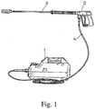
- Fig. 1 shows the basic structure of a high-pressure cleaning device with an under including a feed pump for cleaning liquid, in particular for water Housing 1 with a valve gun 2 with a connected cleaning lance 3 with a nozzle head recognizable at the end or also with a directly connected one Nozzle head and with one leading from the feed pump to the valve gun 2 Pressure line 4.
- FIG. 2 Using the first exemplary embodiment of a bypass valve arrangement according to FIG. 2 the further structure is explained. Is indicated in Fig. 2, the feed pump 5 for the Cleaning liquid, usually water or a water / cleaning agent mixture.
- a common valve housing 6 of the bypass valve arrangement is shown here, on or in which all components of the bypass valve arrangement are arranged are.
- the individual components of the Bypass valve arrangement it is of course also possible to use the individual components of the Bypass valve arrangement to arrange all or some separately from one another and over to connect pressure-resistant connecting lines with each other accordingly.
- the bypass valve arrangement has the following components:
- a check valve 7 is located in a drain chamber 8, on which the pressure line 4 is connected or connectable to the valve gun 2 This check valve 7 closes when valve gun 2 is closed.
- a pump pressure connection is provided 9 with the check valve 7 connecting inflow space 10. At the pump pressure connection 9 is a pump pressure line when the bypass valve arrangement is installed 11 connected. The check valve 7 separates the outflow space 8 from the inflow space 10, thus preventing backflow from the pressure line 4.
- bypass valve 14 Separates the inflow space 10 from a bypass space 12 with a bypass connection 13 a bypass valve 14, which has a bypass valve seat 15, a bypass valve body 16 and a valve spring loading the bypass valve body 16 against the bypass valve seat 15 17 has.
- the Bypass valve body 16 designed as a ball, which also corresponds to a frequently selected one Version. This is held in a version 18 in the illustrated embodiment and is made of highly wear-resistant material.
- the bypass connection 13 from the bypass room 12 is with a bypass valve arrangement connected with a return line 19 to a low-pressure area, in particular to the suction side of the feed pump 5 connected.
- First actuating device 20 is provided with which the bypass valve 14 counteracts the spring force of the valve spring 17 is opened as soon as the operating pressure, in particular the pressure in the pressure line 4 exceeds a certain value or one certain pressure difference is exceeded.
- the first actuating device 20 has the bypass valve body 16 from the bypass valve seat 15 lifting actuator 21, which is not in a fixed connection is with the bypass valve body 16, so that only forces that the bypass valve 14th open to be transferred to the bypass valve body 16.
- the actuator 21 is adjusted by an adjusting spring 22, the spring force of which is adjusted by means of a handwheel 23 can be loaded away from the bypass valve body 16 by means of the adjusting spring 22 you can set a certain working pressure.
- With the actuator 21 is connected to an actuating piston 24. This separates one in a cylinder 25 Control chamber 26, which is hydraulically connected to the drain chamber 8.
- the bypass valve 14 With increasing hydraulic pressure, the actuating piston 24 becomes counter to the spring force the adjusting spring 22 is adjusted so that the bypass valve 14 opens. Through a when the valve gun 2 closes the rapid pressure rise that occurs is the bypass valve 14 can accordingly be opened so far that the pressure in the inflow space 10 collapses, because this is via the bypass valve 14 with a sufficiently large Flow cross-section with the one at low pressure or without pressure Return line 19 is connected.
- the bypass valve 14 has a second actuating device 30 is assigned.
- the second actuating device 30 has a cylinder 31 and therein a relief piston connected to the bypass valve body 16 32 on the valve spring 17 in the closed position of the bypass valve 14 is charged.
- the relief piston 32 hydraulically separates in the cylinder 31 with the drain chamber 8 connected first control chamber 33 with an opening direction of the bypass valve 14 acting piston surface and one in the illustrated embodiment with the inflow space 10 connected second control chamber 34 with a piston surface acting in the closing direction of the bypass valve 14 from each other.
- the term "cylinder" is to be understood comprehensively, meaning the section of the housing, the control chambers sealed against each other with the associated piston forms.
- a valve arrangement 35 is controlled by the relief piston 32, which according to a certain lead (a certain distance) of the relief piston 32 in Opening direction of the bypass valve 14 is a hydraulic connection from the drain chamber 8 to an area of the bypass valve arrangement that is closed Check valve 7 and open bypass valve 14 a significantly below the working pressure has residual pressure. In the illustrated embodiment this area of the bypass valve arrangement of the inflow space 10, but that is not imperative, one could also think of other areas of the bypass valve arrangement.
- the actuator 21 of the first actuator 20 with the bypass valve body 16 is not firmly connected affects the position of the bypass valve body 16 in this context, the position of the actuating element 21 is not.
- the open position of the bypass valve 14 is also raised of the bypass valve body 16 from the bypass valve seat 15 no longer from that Actuating element 21 dependent on the first actuating device 20. So it bothers not that the pressure drop in the control chamber 26, which is hydraulic with the drain chamber 8 is connected in which the pressure has now been reduced to the holding pressure has led to the actuating piston 24 under the action of the adjusting spring 22 has been withdrawn and the bypass valve body 16 is not touched more.
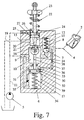
- Fig. 7 of the drawing shows a variant in which the control chamber 26 is hydraulically connected to the inflow space 10. This is one in practice constructive reasons possibly preferred variant. Both types are known from the prior art. This variant is only the one claimed Realizable solution. This is because the initial surge will bypass valve 14 opens, but then the second actuating device 30 keeps the bypass valve open takes over.
- FIGS. 2, 3, 4, 5, 6 shows how the bypass valve arrangement works is in operation.
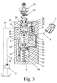
- FIG. 3 shows the situation when the feed pump 5 is running and the valve gun 2 is open, so in operation. Due to the fast flowing cleaning fluid, the check valve 7 held in the open position, the bypass valve arrangement is under operating pressure. This can be seen in particular from the fact that the actuating piston 24 counter to the spring force of the adjusting spring 22 has moved somewhat downwards. The from Drain chamber 8 via a connecting line 27 to the control chamber 26 operating pressure has a corresponding force effect on the upper surface of the actuating piston 24 in a row. The displacement of the actuating piston 24 has thanks Corresponding vote just led to the actuating element 21st stands directly on the bypass valve body 16, but not yet from the bypass valve seat 15 has lifted off.
- Fig. 4 shows the state in which the valve gun 2 has now been closed.
- the rapid pressure rise (pressure shock) occurring when the valve gun 2 is closed on the one hand has closed the check valve 7, on the other hand the actuating piston 24 quickly pressed down so that the actuator 21 the bypass valve body 16 has lifted off the bypass valve seat 15.
- the bypass valve 14 is open, the feed pump 5 delivers directly in the circuit from the pump pressure line 11 via the inflow space 10 and the bypass valve 14 into the bypass space 12 and the Return line 19.
- the pressure in the pressure line 4 has the Working pressure of the first actuator 20 significantly exceeded.
- FIG. 4 also shows that the pressure in the pressure line 4 or the discharge space 8 via a connecting line 36 of the second actuating device 30 is fed.
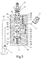
- 4 of the position of the relief piston 32 which is taken up by the displacement of the bypass valve body 16 moves the relief piston 32 in the transition according to FIG. 5 of the drawing under the Influence of the pressure in the drain chamber 8 further down.
- the relief piston takes off 32 via a piston rod 37 the bypass valve body firmly attached to it 16 continue with down.
- a throttle point 38 In the connecting line 36 from the drainage space 8 for the first control chamber 33 is in the illustrated embodiment a throttle point 38. This causes the inflow of hydraulic fluid into the first control chamber 33 not suddenly, but slowly, the relief piston 32 is slowly moved down. There is in this area no pressure shock. This is prevented by the throttle point 38.
- valve arrangement 35 now shows the position in which the valve arrangement 35 is opened.
- the relief piston 32 namely has the specific flow in the opening direction of the bypass valve 14 traveled.
- the hydraulic arrangement is made by means of the valve arrangement 15 Connection from the discharge space 8 to an area of the bypass valve arrangement produced, which is below the previously explained residual pressure, which is significantly below the working pressure is located.
- the area of the bypass valve arrangement which has the residual pressure the inflow space is 10.
- the illustrated and so far preferred embodiment further shows that the Valve arrangement 35 from the relief piston 32 in connection with detour lines 39 formed on the wall of the cylinder 31 of the second actuator 30 is.
- the detour lines 39 can be in the form of simple cutouts or notches in the wall of the cylinder 31 may be formed. It can also be real bypass channels act.
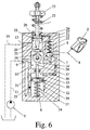
- the pressure in the discharge chamber 8 is now at a holding pressure lowered by the residual pressure in the system and by the spring force of the Valve spring 17 generated pressure is determined. If this holding pressure is reached, then from the bypass valve arrangement in the position shown in FIG. 6.
- the Bypass valve body 16 is adjusted back in the direction of the bypass valve seat 15 been, but has not reached the bypass valve seat 15, the bypass valve 14 is open unchanged. Since the holding pressure in the drain chamber 8 is very much is lower than the working pressure of the first actuating device 20, the actuating piston 24 of the first actuating device 20 under the action of the adjusting spring 22, as can be seen, again reached its upper position as in FIG. The opening position of the bypass valve 14 is therefore no longer the first in this situation Actuator 20, but only from the second actuator 30 determined.
- Each actuator has an element for production a fixed or adjustable force, especially just a spring on and a pressurized piston assembly.
- the elements of the first actuator are on the range of the working pressure with the consumer switched on matched, the elements of the second actuator are on the accumulator pressure the system with the consumer switched off, i.e. the holding pressure adjusted.
- the holding pressure in the system can be selected to be significantly lower than that of the Bypass valve arrangements implemented in the prior art, that has the ones explained at the beginning safety advantages.
- FIG. 7 differs from that in FIG. 2 illustrated embodiment only in that in the first actuator 20 the connecting line 27 to the control chamber 26 to the inflow space 10, does not lead to the drainage space 8. So here it is the pressure in the inflow space 10 that the Movement of the actuating piston 24 of the first actuating device 20 controls.
- FIGS. 1 to 7 show a fixed setting Advance of the relief piston 32 of the second actuator 30. It is but also conceivable that this lead is variably adjustable. In a similar way here the spring force of the valve spring 17 is fixed. It could be done easily also imagine that the spring force of the valve spring 17 is variably adjustable, for example by means of a threaded spindle inserted into the second control chamber 34 from the outside, with which the abutment of the valve spring 17 could be adjusted. On this way you can adjust the system holding pressure.
- the bypass valve body 16 is itself in the inflow space 10 arranged.
- a known from the prior art is also conceivable Arrangement of the bypass valve body 16 itself in the bypass chamber 12, that is on the other side of the passage.
- the bypass valve seat 15 would have to be accordingly be relocated.
- Such an arrangement is the subject of the prior art Technology from DE-U-295 21 372, however, in the prior art discussed there the arrangement of the bypass valve body 16 in the inflow space 10 is shown.
- a complete or partial pressure compensation of the bypass valve body 16 is also a possibility that need not be described further here.
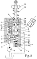
- the further exemplary embodiment of the bypass valve arrangement according to the invention shown in FIG. 8 differs from that explained in the preceding figures Embodiment in that the second control chamber 34 of the second Actuator 30 is not connected to the inflow space 10 but with the bypass chamber 12 is connected.
- the relief piston 32 is guided in a pressure-tight manner between the discharge space 8 and the bypass space 12 is located while the bypass valve body 16 is in the inflow space 10.
- the Drainage space 8 and the bypass space 12 with the implementation in between therefore form the cylinder 31 for the relief piston 32.
- the valve spring 17 is actuated directly the bypass valve body 16 and via this the relief piston 32, while in the previously described embodiment, the valve spring 17 immediately rests on the relief piston 32.
- the valve arrangement 35 of the second actuating device 30 is one with here Valve body 40 and valve seat 41.
- Valve body 40 and valve seat 41 is an additional connecting line 42 from the drainage space 8 to a relief space 43 of the valve arrangement 35.
- the valve assembly 35 is actuated as soon as the pressure in the discharge chamber 8 Relief piston 32 has moved around the lead. Then the lower one hits End of the bypass valve body 16 on an actuating rod 44 for the valve body 40 of the valve assembly 35 and presses it against the spring force of the valve spring 45 downward, so that the valve body 40 lifts off the valve seat 41 and the drainage space 8 connects to the inflow space 10.
- the actuating element 21 is on the actuating piston 24 guided in a pressure-tight manner via a seal 50 into the discharge space 8, the further control chamber 51 thus formed on the actuating piston 24 via a Vent opening 52 is connected to the ambient atmosphere.
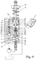
- FIG. 9 The further exemplary embodiment shown in FIG. 9 is based on the working principle of the embodiment shown in Fig. 8. It is also provided here that the valve arrangement 35 in the interior of the bypass valve body 16 or here this one-piece relief piston 32 is located.
- the valve assembly 35 is arranged so that the opening direction opposite to the opening direction of the bypass valve 14.
- the interior of the bypass valve body 16 or relief piston 32 has one in the section lying in the discharge chamber 8 Connection opening 53 to the drainage space 8.
- the valve body lies in this area 40 of the valve arrangement 35 with the valve spring 45.
- the actuating rod 44 protrudes downward into the relief space 43, which is connected to the inflow space 10 is.
- An adjustable stop 54 for the actuating rod 44 defines the advance, which can be variably adjusted here.
- the invention also relates to a high-pressure cleaning device with a Bypass valve arrangement as previously described.
Landscapes
- Engineering & Computer Science (AREA)
- Mechanical Engineering (AREA)
- General Engineering & Computer Science (AREA)
- Safety Valves (AREA)
- Details Of Reciprocating Pumps (AREA)
- Multiple-Way Valves (AREA)
Abstract
Description
- Fig. 1
- in schematischer, einen Überblick gebender Darstellung eine Hochdruckreinigungseinrichtung üblicher Bauart,
- Fig. 2
- ein erstes Ausführungsbeispiel einer erfindungsgemäßen Bypassventilanordnung, Förderpumpe des Hochdruckreinigungsgerätes ausgeschaltet druckloser Zustand,
- Fig. 3
- die Bypassventilanordnung aus Fig. 2 im Betrieb mit laufender Förderpumpe und geöffneter Ventilpistole,
- Fig. 4
- die Bypassventilanordnung aus Fig. 2 mit laufender Förderpumpe, jedoch geschlossener Ventilpistole und geöffnetem Bypassventil, Druckleitung noch nicht entlastet,
- Fig. 5
- die Bypassventilanordnung aus Fig. 2 in einer zeitlich Fig. 4 nachgeordneten Phase, nämlich bei Beginn der Druckentlastung der Druckleitung,
- Fig. 6
- die Bypassventilanordnung aus Fig. 2 in einer Fig. 5 nachgeordneten Phase, nämlich nach Abschluß der Druckentlastung der Druckleitung,
- Fig. 7
- ein zweites Ausführungsbeispiel einer erfindungsgemäßen Bypassventilanordnung in einer Fig. 2 entsprechenden Darstellung,
- Fig. 8
- ein drittes Ausführungsbeispiel einer erfindungsgemäßen Bypassventilanordnung in einer Fig. 2 entsprechenden Darstellung,
- Fig. 9
- ein viertes Ausführungsbeispiel einer erfindungsgemäßen Bypassventilanordnung in einer Fig. 2 entsprechenden Darstellung.
Claims (10)
- Bypassventilanordnung für ein Hochdruckreinigungsgerät mit einer Förderpumpe (5) für Reinigungsflüssigkeit, miteinem Rückschlagventil (7) zwischen einem Abflußraum (8), an den eine Druckleitung (4) zu einer Ventilpistole (2) o. dgl. anschließbar ist, und einem Zuflußraum (10) mit einem Pumpendruckanschluß (9), wobei das Rückschlagventil (7) bei Schließen der Ventilpistole (2) o. dgl. schließt,einem den Zuflußraum (10) von einem Bypassraum (12) mit Bypassanschluß (13) abtrennenden Bypassventil (14) mit Bypassventilsitz (15), Bypassventilkörper (16) und den Bypassventilkörper (16) gegen den Bypassventilsitz (15) belastender Ventilfeder (17) o. dgl.,einer ersten Betätigungseinrichtung (20) für das Bypassventil (14) mit einem den Bypassventilkörper (16) vom Bypassventilsitz (15) abhebenden Betätigungselement (21) ohne feste Verbindung mit dem Bypassventilkörper (16), einer das Betätigungselement (21) vom Bypassventilkörper (16) weg belastenden, einen bestimmten, vorzugsweise einstellbaren Arbeitsdruck definierenden Einstellfeder (22) o. dgl. und einem mit dem Betätigungselement (21) verbundenen Betätigungskolben (24), der eine Steuerkammer (26) abtrennt,
wobei der Betätigungskolben (24) bei ansteigendem Hydraulikdruck entgegen der Kraft der Einstellfeder (22) o. dgl. so verstellt wird, daß das Bypassventil (14) öffnet, wobei durch einen beim Schließen der Ventilpistole (2) o. dgl. auftretenden schnellen Druckanstieg das Bypassventil (14) so weit öffenbar ist, daß der Druck im Zuflußraum (10) zusammenbricht,
gekennzeichnet durch folgende Merkmale:a) Dem Bypassventil (14) ist eine zweite Betätigungseinrichtung (30) zugeordnet.b) Die zweite Betätigungseinrichtung (30) weist einen Zylinder (31) und darin einen mit dem Bypassventillkörper (16) verbundenen Entlastungskolben (32) auf, der von der Ventilfeder (17) o. dgl. in Schließrichtung des Bypassventiis (14) belastet ist.c) Der Entlastungskolben (32) trennt im Zylinder (31) eine hydraulisch mit dem Abflußraum (8) verbundene erste Steuerkammer (33) mit einerin Öffnungsrichtung des Bypassventils (14) wirkenden Kolbenfläche und eine hydraulisch mit dem Zuflußraum (10) oder dem Bypassraum (12) verbundene zweite Steuerkammer (34) mit einer in Schließrichtung des Bypassventils (14) wirkenden Kolbenfläche voneinander.d) Vom Entlastungskolben (32) wird eine Ventilanordnung (35) gesteuert, die nach einem bestimmten Vorlauf des Entlastungskolbens (32) in Öffnungsrichtung des Bypassventils (14) eine hydraulische Verbindung vom Abflußraum (8) zu einem Bereich der Bypassventilanordnung herstellt, der bei geschlossenem Rückschlagventil (7) und geöffnetem Bypassventil (14) einen erheblich unter dem Arbeitsdruck liegenden Restdruck aufweist.e) Nach Absinken des Drucks im Abflußraum (8) auf einen vom Restdruck und vom durch die Kraft der Ventilfeder (17) o. dgl. erzeugten Druck bestimmten Haltedruck wird durch Rückstellung des Entlastungskolbens (32) die Ventilanordnung (35) wieder geschlossen, dabei aber der Bypassventilkörper (16) vom Bypassventilsitz (15) abgehoben gehalten. - Bypassventilanordnung nach Anspruch 1, dadurch gekennzeichnet, daß die Steuerkammer (26) hydraulisch mit dem Abflußraum (8) oder, vorzugsweise, mit dem Zuflußraum (10) verbunden ist.
- Bypassventilanordnung nach Anspruch 1 oder 2, dadurch gekennzeichnet daß die Komponenten der Bypassventilanordnung in und an einem gemeinsamen Ventilgehäuse (6) angeordnet sind, und/oder daß der Vorlauf des Entlastungskolbens (32) variabel einstellbar ist und/oder daß die Kraft der Ventilfeder (17) o. dgl. variabel einstellbar ist, und/oder daß in der hydraulischen Verbindung zwischen dem Abflußraum (8) und der ersten Steuerkammer (33) eine Drosselstelle (38) angeordnet ist.
- Bypassventilanordnung nach einem der Ansprüche 1 bis 3, dadurch gekennzeichnet, daß der den Restdruck aufweisende Bereich der Bypassventilanordnung der Zuflußraum (10) oder der Bypassraum (12) ist.
- Bypassventilanordnung nach einem der Ansprüche 1 bis 4, dadurch gekennzeichnet, daß die Ventilanordnung (35) vom Entlastungskolben (32) in Verbindung mit Umwegleitungen (39) an der Wandung des Zylinders (31) der zweiten Betätigungseinrichtung (30) gebildet ist.
- Bypassventilanordnung nach einem der Ansprüche 1 bis 4, dadurch gekennzeichnet daß die Ventilanordnung (35) einen Ventilkörper (40) und einen Ventilsitz (41) aufweist und, vorzugsweise, daß die Ventilanordnung (35) zwischen dem Abflußraum (8) und dem Zuflußraum (10) vom Bypassventilkörper (16) betätigt wird, sobald der Druck im Abflußraum (8) den Entlastungskolben (32) um den Vorlauf bewegt hat.
- Bypassventilanordnung nach Anspruch 6, dadurch gekennzeichnet, daß die Ventilanordnung (35) im Inneren des Bypassventilkörpers (16) bzw. des Entlastungskolbens (32) angeordnet ist und, vorzugsweise, daß die Öffnungsrichtung der Ventilanordnung (35) der Öffnungsrichtung des Bypassventils (14) entgegengerichtet ist und daß der Bypassventilkörper (16) bzw. der Entlastungskolben (32) über eine Verbindungsöffnung (53) mit dem Abflußraum (8) in Verbindung steht.
- Bypassventilanordnung nach Anspruch 7, dadurch gekennzeichnet, daß die Ventilanordnung (35) durch einen im Zuflußraum angeordneten Anschlag (54) geöffnet wird, sobald der Druck im Abflußraum (8) den Bypassventilkörper (16) entgegen der Kraft der Ventilfeder (17) o. dgl. um den Vorlauf in Öffnungsrichtung verschoben hat.
- Bypassventilanordnung nach Anspruch 8, dadurch gekennzeichnet, daß der Anschlag (54) einstellbar ist.
- Hochdruckreinigungsgerät mit einer Förderpumpe (5) für Reinigungsflüssigkeit,, gekennzeichnet durch eine Bypassventilanordnung nach einem der Ansprüche 1 bis 9.
Applications Claiming Priority (4)
| Application Number | Priority Date | Filing Date | Title |
|---|---|---|---|
| DE19836407 | 1998-08-12 | ||
| DE19836407 | 1998-08-12 | ||
| DE19838947 | 1998-08-27 | ||
| DE19838947A DE19838947C1 (de) | 1998-08-12 | 1998-08-27 | Bypassventilanordnung für ein Hochdruckreinigungsgerät sowie Hochdruckreinigungsgerät mit einer solchen Bypassventilanordnung |
Publications (2)
| Publication Number | Publication Date |
|---|---|
| EP0979944A2 true EP0979944A2 (de) | 2000-02-16 |
| EP0979944A3 EP0979944A3 (de) | 2000-10-18 |
Family
ID=26048086
Family Applications (1)
| Application Number | Title | Priority Date | Filing Date |
|---|---|---|---|
| EP99115736A Withdrawn EP0979944A3 (de) | 1998-08-12 | 1999-08-10 | Bypassventilanordnung für ein Hochdruckreinigungsgerät sowie Hochdruckreinigungsgerät mit einer solchen Bypassventilanordnung |
Country Status (1)
| Country | Link |
|---|---|
| EP (1) | EP0979944A3 (de) |
Cited By (1)
| Publication number | Priority date | Publication date | Assignee | Title |
|---|---|---|---|---|
| EP2093643A2 (de) | 2008-02-19 | 2009-08-26 | P.A. S.p.A. | Bypass- und Drucksteuerventil |
Family Cites Families (2)
| Publication number | Priority date | Publication date | Assignee | Title |
|---|---|---|---|---|
| DE3810341A1 (de) * | 1988-03-17 | 1989-09-28 | Suttner Gmbh & Co Kg | Fluessigkeitsfoerdereinrichtung, insbesondere hochdruckreinigungseinrichtung |
| DE4221192A1 (de) * | 1992-06-27 | 1994-01-05 | Kaercher Gmbh & Co Alfred | Hochdruckreinigungsgerät |
-
1999
- 1999-08-10 EP EP99115736A patent/EP0979944A3/de not_active Withdrawn
Cited By (4)
| Publication number | Priority date | Publication date | Assignee | Title |
|---|---|---|---|---|
| EP2093643A2 (de) | 2008-02-19 | 2009-08-26 | P.A. S.p.A. | Bypass- und Drucksteuerventil |
| JP2009197995A (ja) * | 2008-02-19 | 2009-09-03 | Pa Spa | 改良されたバイパス及び圧力調整弁 |
| EP2093643A3 (de) * | 2008-02-19 | 2010-07-21 | P.A. S.p.A. | Bypass- und Drucksteuerventil |
| US8091576B2 (en) | 2008-02-19 | 2012-01-10 | P.A. S.P.A. | By-pass and pressure regulator valve |
Also Published As
| Publication number | Publication date |
|---|---|
| EP0979944A3 (de) | 2000-10-18 |
Similar Documents
| Publication | Publication Date | Title |
|---|---|---|
| DE2249181C3 (de) | Hydraulische Lenkbegrenzung für Servolenkanlagen, insbesondere für Kraftfahrzeuge | |
| EP2425164B1 (de) | Proportional-drosselventil | |
| DE4330073A1 (de) | Vorgesteuertes Hydraulikventil | |
| LU88390A1 (de) | Vorsteuerstufe fuer Druckbegrenzungsventile | |
| EP1574474A2 (de) | Hydraulische Anordnung | |
| DE4108915C2 (de) | Hydraulische Einrichtung zur Druckmittelversorgung eines bevorrechtigten Primärlastkreises | |
| DE2243585B2 (de) | Hydropneumatische Federung für Kraftfahrzeuge | |
| EP3012463B1 (de) | Hydraulikaggregat | |
| EP0174482B1 (de) | Zweistellungs-Schaltventil mit hydraulischer Selbsthaltung | |
| DE2533164C3 (de) | Hydraulische Steuereinrichtung für ein Hydrauliksystem | |
| DE3810341C2 (de) | ||
| DE3922553C2 (de) | Vorrichtung zur Entlastung eines unter hohem Druck stehenden mit Hydraulikflüssigkeit gefüllten Arbeitsraumes | |
| DE102006060333B3 (de) | Hydraulische Ventilanordnung | |
| DE19838947C1 (de) | Bypassventilanordnung für ein Hochdruckreinigungsgerät sowie Hochdruckreinigungsgerät mit einer solchen Bypassventilanordnung | |
| DE2728004C2 (de) | Hydraulische Steuervorrichtung für einen Servomotor, insbesondere für Fahrzeuglenkungen | |
| DE3320047C2 (de) | ||
| EP1497559A1 (de) | Hydraulische steueranordnung in load-sensing technik | |
| WO2011061171A1 (de) | Mehrstufig schaltbare vorgesteuerte ventilanordnung | |
| DE3508432C2 (de) | ||
| EP0979944A2 (de) | Bypassventilanordnung für ein Hochdruckreinigungsgerät sowie Hochdruckreinigungsgerät mit einer solchen Bypassventilanordnung | |
| DE2812765A1 (de) | Bremseinrichtung fuer den anhaenger eines fahrzeugs, das einen von einer druckmittelquelle gespeisten hydraulikkreis mit einem verbraucher hat | |
| EP2019240A1 (de) | Hydraulisches Lastschaltventil mit RC-Glied | |
| DE3630454C1 (en) | Device for controlling hydraulic drives | |
| CH649360A5 (de) | Hydraulisch entsperrbare ventilanordnung. | |
| DE19505333C2 (de) | Hydraulikantrieb |
Legal Events
| Date | Code | Title | Description |
|---|---|---|---|
| PUAI | Public reference made under article 153(3) epc to a published international application that has entered the european phase |
Free format text: ORIGINAL CODE: 0009012 |
|
| AK | Designated contracting states |
Kind code of ref document: A2 Designated state(s): AT BE CH CY DE DK ES FI FR GB GR IE IT LI LU MC NL PT SE |
|
| AX | Request for extension of the european patent |
Free format text: AL;LT;LV;MK;RO;SI |
|
| PUAL | Search report despatched |
Free format text: ORIGINAL CODE: 0009013 |
|
| AK | Designated contracting states |
Kind code of ref document: A3 Designated state(s): AT BE CH CY DE DK ES FI FR GB GR IE IT LI LU MC NL PT SE |
|
| AX | Request for extension of the european patent |
Free format text: AL;LT;LV;MK;RO;SI |
|
| AKX | Designation fees paid | ||
| STAA | Information on the status of an ep patent application or granted ep patent |
Free format text: STATUS: THE APPLICATION IS DEEMED TO BE WITHDRAWN |
|
| 18D | Application deemed to be withdrawn |
Effective date: 20010419 |
|
| REG | Reference to a national code |
Ref country code: DE Ref legal event code: 8566 |