EP0979751A2 - Vehicle seat support frame with left and right forward adjustment arms - Google Patents
Vehicle seat support frame with left and right forward adjustment arms Download PDFInfo
- Publication number
- EP0979751A2 EP0979751A2 EP99111912A EP99111912A EP0979751A2 EP 0979751 A2 EP0979751 A2 EP 0979751A2 EP 99111912 A EP99111912 A EP 99111912A EP 99111912 A EP99111912 A EP 99111912A EP 0979751 A2 EP0979751 A2 EP 0979751A2
- Authority
- EP
- European Patent Office
- Prior art keywords
- swivel
- support
- seat
- support frame
- outside
- Prior art date
- Legal status (The legal status is an assumption and is not a legal conclusion. Google has not performed a legal analysis and makes no representation as to the accuracy of the status listed.)
- Granted
Links
- 239000003351 stiffener Substances 0.000 claims abstract description 8
- 239000002184 metal Substances 0.000 description 2
- 210000002455 dental arch Anatomy 0.000 description 1
- 238000003466 welding Methods 0.000 description 1
Images

Classifications
-
- B—PERFORMING OPERATIONS; TRANSPORTING
- B60—VEHICLES IN GENERAL
- B60N—SEATS SPECIALLY ADAPTED FOR VEHICLES; VEHICLE PASSENGER ACCOMMODATION NOT OTHERWISE PROVIDED FOR
- B60N2/00—Seats specially adapted for vehicles; Arrangement or mounting of seats in vehicles
- B60N2/24—Seats specially adapted for vehicles; Arrangement or mounting of seats in vehicles for particular purposes or particular vehicles
- B60N2/26—Seats specially adapted for vehicles; Arrangement or mounting of seats in vehicles for particular purposes or particular vehicles for children
- B60N2/28—Seats readily mountable on, and dismountable from, existing seats or other parts of the vehicle
- B60N2/2887—Fixation to a transversal anchorage bar, e.g. isofix
- B60N2/2893—Fixation to a transversal anchorage bar, e.g. isofix coupled to the seat sub-frame
-
- B—PERFORMING OPERATIONS; TRANSPORTING
- B60—VEHICLES IN GENERAL
- B60N—SEATS SPECIALLY ADAPTED FOR VEHICLES; VEHICLE PASSENGER ACCOMMODATION NOT OTHERWISE PROVIDED FOR
- B60N2/00—Seats specially adapted for vehicles; Arrangement or mounting of seats in vehicles
- B60N2/02—Seats specially adapted for vehicles; Arrangement or mounting of seats in vehicles the seat or part thereof being movable, e.g. adjustable
- B60N2/04—Seats specially adapted for vehicles; Arrangement or mounting of seats in vehicles the seat or part thereof being movable, e.g. adjustable the whole seat being movable
- B60N2/16—Seats specially adapted for vehicles; Arrangement or mounting of seats in vehicles the seat or part thereof being movable, e.g. adjustable the whole seat being movable height-adjustable
- B60N2/1605—Seats specially adapted for vehicles; Arrangement or mounting of seats in vehicles the seat or part thereof being movable, e.g. adjustable the whole seat being movable height-adjustable characterised by the cinematic
- B60N2/161—Rods
- B60N2/1615—Parallelogram-like structure
-
- B—PERFORMING OPERATIONS; TRANSPORTING
- B60—VEHICLES IN GENERAL
- B60N—SEATS SPECIALLY ADAPTED FOR VEHICLES; VEHICLE PASSENGER ACCOMMODATION NOT OTHERWISE PROVIDED FOR
- B60N2/00—Seats specially adapted for vehicles; Arrangement or mounting of seats in vehicles
- B60N2/02—Seats specially adapted for vehicles; Arrangement or mounting of seats in vehicles the seat or part thereof being movable, e.g. adjustable
- B60N2/04—Seats specially adapted for vehicles; Arrangement or mounting of seats in vehicles the seat or part thereof being movable, e.g. adjustable the whole seat being movable
- B60N2/16—Seats specially adapted for vehicles; Arrangement or mounting of seats in vehicles the seat or part thereof being movable, e.g. adjustable the whole seat being movable height-adjustable
- B60N2/1635—Seats specially adapted for vehicles; Arrangement or mounting of seats in vehicles the seat or part thereof being movable, e.g. adjustable the whole seat being movable height-adjustable characterised by the drive mechanism
- B60N2/165—Gear wheel driven mechanism
Definitions
- the invention relates to a seat support frame of a vehicle seat with a left and a right side part and a left and a right, front Swivel support arm, with the left swivel support in the front area of the left
- the right swivel support is articulated in the front area of the right Is articulated on the side and an adjustment device is provided with which the The inclination of the two swivel supports can be adjusted.
- the left pair of rails the longitudinal guidance of the motor vehicle seat essentially perpendicularly below the left side part of the seat support, as well as the right pair of rails the longitudinal guide substantially perpendicular below the right side part of the seat support frame located.
- At least the arrangement is symmetrical in many cases, if there is an offset, it is mirror-symmetrical on both sides of the seat.
- the aim is to stiffen the pairs of rails as close as possible to the side Arrange areas of the floor assembly, i.e. the pair of rails on the outside of the vehicle near the sill there or directly on the sill and inside the vehicle Attach a pair of rails near the tunnel there or directly to the tunnel.
- the invention is concerned with a seat frame for this case.
- the invention has for its object to provide a seat frame that is strong laterally offset arrangement of a seat support compared to a longitudinal guide suitable and the mechanical loads that occur due to the one-sided offset intercepts in the simplest possible way.
- This task is based on the seat support frame of the type mentioned solved in that a swivel support a) on the outside of its associated Is arranged side, b) starting from the articulation with this The side part is exposed to the outside, c) one transverse to its plane of movement has running stiffening and d) with the other swivel support a cross tube is rigidly connected.
- the one front pivot support is strongly exhibited while the other swivel support (the other side of the seat) is not.
- This swivel bracket essentially absorbs the large offset on the corresponding seat side is provided for the associated pair of rails.
- the offset on the other side of the seat on the other hand is significantly smaller, for example three to five times smaller.
- the bracing ensures that the corresponding front swivel support also has sufficient strength transversely to their plane of movement. Accordingly The bracing runs transverse to its plane of movement.
- the plane of movement The swivel bracket is the plane in which it moves when it is around its pivot point is pivoted on the associated swivel support.
- the two swivel supports are rigidly connected to each other by the cross tube into a substantially H-shaped unit.
- the adjustment forces directed to both swivel supports at the same time.
- Through the cross tube an additional Bracing is achieved because the lateral ones act on the swivel support Forces are also transmitted to the other swivel support via the cross tube. It is preferred that the connection of the cross tube to the swivel supports essentially takes place in the longitudinal center of the swivel supports.
- the outside of the vehicle is front swivel support that has the bracing. That way it can vehicle pair of rails on the outside are displaced relatively far to the side, thus a large offset between a vertical through the associated swivel support and the vehicle-side pair of rails occur.
- the mechanical effect of the bracing is increased by the fact that it Cross tube is connected. This also uses the cross tube, the lateral stiffness to increase the more extended swivel support.
- the outside of the vehicle which is provided with the bracing, is preferably issued to the outside world at least three times, in particular at least five times more than the other, vehicle-side or vehicle-side swivel support.
- the seat is thus arranged relatively asymmetrically to the longitudinal guide.
- the other pivot support is an essentially flat part.
- the cross tube is at an angle of 10 up to 30 degrees to the main direction of the more exposed, preferably the outside of the vehicle Swivel support runs.
- the seat support has a left side part 20 right side part 22 and a rear traverse 24.
- the labels left and right and front and back are always seen in relation to a passenger, who sits down on the seat support.
- a rear cross shaft 26 on which a left and a right adjusting arm 28 are fixed, for example welded on. How from 1 can be seen, the transverse shaft 26 projects freely beyond the right adjusting arm 28, so that this free end region is inserted into a bearing bore 30 of the right side part 22 can be.
- the locking ring 32 is used for fixing.
- the left side part 20 has a receiving bay 34 which is open at the bottom. There are holes are provided to the left and right of the receiving bay 34, which act as the first fastening means 36 are referred to.
- a bearing part 38 is arranged around the transverse shaft 26, which on the one hand takes over the mounting of the transverse shaft 26 and on the other hand second Fastening means 40 forms, which are also designed as holes here.
- the bearing part 38 is designed so that it bridges the receiving bay 34 and after attachment on the associated left side part 20 the (actually missing there) bearing hole for forms the left region of the transverse shaft 26. In the embodiment shown the bearing part 38 after assembly on the inside of the left side part 20, that is between the two side parts 20, 22.
- the left actuating arm 28 is located on the other hand, on the outside of the left side part 20.
- a drive part 42 is connected to the transverse shaft 26. It is in the concrete Provide training with a dental arch.
- cross shaft 26 with its two control arms 28, the bearing part 38 and the drive part 42 completely prefabricated as a structural unit can be later, as shown in Figure 1 by the dash-dotted upper assembly line can be seen in the prefabricated unit from the two side parts 20, 22 and the rear cross member 24 can be inserted.
- connection points are detachable, for example using screw connections. They can also be realized with removable rivets.
- connection of the bearing part 38 with the edge region of the receiving bay 34 by means of the fastening means 36, 40 done by welding, riveting, screwing or the like.
- FIG. 2 shows two different cross members 24, 25 can be used.
- the crossbar 24 shown assembled is a normal crossbar. She has known in Wise brackets for accommodating seat springs that run forward. they are not shown here. By loosening the four connection points that run accordingly are, the cross member 24 can be replaced by a cross member 25 with brackets for an Isofix attachment. This is due to the four dash-dotted lines that are parallel to each other Assembly lines shown.
- the traverse 25 differs with the exception of two Isofix brackets not from the traverse 24.
- a front swivel bridge 44 is also shown in FIGS. 1 and 2.
- she consists from a cross tube 50 and two pivot supports 52, 54, each at its upper End and at their lower end have a bearing hole and approximately in their central area are firmly connected to each other by the cross tube 50.
- This unit too can be pre-assembled and subsequently integrated into the described arrangement, as is also evident from the two lower dash-dotted assembly lines becomes.
- connecting means which are designed here as screws 56 and nuts 58.
- the right pivot support 54 is a substantially flat one Sheet metal stamping. As can be seen from FIG. 2, it is on the outside of the right one Side part 22 arranged. There is a right one essentially perpendicular to it Rail pair 60 of a longitudinal guide. In contrast, the left pivot support 52 is strong Flown outwards and downwards, so runs obliquely. As a result, an associated, left pair of rails 62 is at a distance d from a vertical through the connection area between the left pivot support 42 and the left side part 20 is located, which is also called offset. This offset d is like a comparison with the right side of the seat shows at least three times, preferably at least five times the size of the right side of the seat.
- the left pivot support 52 runs in its connection area with the cross tube 50 at an angle, you can see this from the elliptical connecting line.
- the cross tube 50 runs practically at right angles to the right pivot support 54, one recognizes this by the circular connecting line.
- the left pivot support 52 has a stiffener 64 in the form of a triangular piece of sheet metal, which is preferably in one piece with the actual pivot support 52 is related and is bent out of its plane so that it is essentially transversely to the plane of movement in which the left pivot support 52 about its articulation point pivots on the left side, stands.
- the stiffener 64 runs downwards off, it is connected to the cross tube 50 at the top, along a triangular side. It is it is also possible to use an appropriate stiffener above the cross tube, but which is not shown here.
- a front crossmember (not shown) can be arranged here.
- the two side parts 20, 22 are essentially Identical in design, but differ in the area of the bearing bore 30 or the receiving bay 34.
- a hole in the Side part 20 is provided, which is designed here as a bearing 46.
- a in the area around the bearing 46 Electric motor 48 are flanged. It has the following special feature: its gearbox is open in the area facing the side part 20, so there is no one there Housing wall of the gear housing.
- the side part 20 takes over in the area around the Bearing 46 around the function of the missing housing wall of the gear housing. On this saves weight, it becomes a precise bearing of the output shaft of the electric motor 48 in the side part 20 and the assignment to the drive part 42 is cheap.
Landscapes
- Engineering & Computer Science (AREA)
- Aviation & Aerospace Engineering (AREA)
- Transportation (AREA)
- Mechanical Engineering (AREA)
- Health & Medical Sciences (AREA)
- Child & Adolescent Psychology (AREA)
- General Health & Medical Sciences (AREA)
- Seats For Vehicles (AREA)
Abstract
Description
Die Erfindung bezieht sich auf ein Sitzträgergestell eines Fahrzeugsitzes mit einem linken und einem rechten Seitenteil und einer linken und einer rechten, vorderen Schwenkstützelarm, wobei die linke Schwenkstütze im Vorderbereich des linken Seitenteils angelenkt ist, die rechte Schwenkstütze im Vorderbereich des rechten Seitenteils angelenkt ist und eine Verstelleinrichtung vorgesehen ist, mit der die Neigung der beiden Schwenkstützen eingestellt werden kann.The invention relates to a seat support frame of a vehicle seat with a left and a right side part and a left and a right, front Swivel support arm, with the left swivel support in the front area of the left The right swivel support is articulated in the front area of the right Is articulated on the side and an adjustment device is provided with which the The inclination of the two swivel supports can be adjusted.
Bei Kraftfahrzeugsitzen besteht häufig eine Zuordnung, dass sich das linke Schienenpaar der Längsführung des Kraftfahrzeugsitzes im wesentlichen lotrecht unterhalb des linken Seitenteils des Sitzträgers befindet, ebenso dass sich das rechte Schienenpaar der Längsführung im wesentlichen lotrecht unterhalb des rechten Seitenteils des Sitzträgergestells befindet. Zumindest ist die Anordnung in vielen Fällen symmetrisch, wenn also ein Versatz vorhanden ist, ist er auf beiden Sitzseiten spiegelsymmetrisch.In motor vehicle seats, there is often an assignment that the left pair of rails the longitudinal guidance of the motor vehicle seat essentially perpendicularly below the left side part of the seat support, as well as the right pair of rails the longitudinal guide substantially perpendicular below the right side part of the seat support frame located. At least the arrangement is symmetrical in many cases, if there is an offset, it is mirror-symmetrical on both sides of the seat.
Nun ist man bestrebt, die Schienenpaare möglichst in Nähe der seitlichen, versteiften Bereiche der Bodengruppe anzuordnen, also das fahrzeugaußenseitige Schienenpaar in Nähe des dortigen Schwellers oder direkt am Schweller und das fahrzeuginnenseitige Schienenpaar in Nähe des dortigen Tunnels oder direkt am Tunnel zu befestigen. Dies führt dazu, dass die bisher gewohnte, symmetrische Anordnung zwischen Längsführung und Sitzträgergestell nicht immer beibehalten werden kann, insbesondere dass ein nureinseitiger seitlicher Versatz auftritt. Die Erfindung beschäftigt sich mit einem Sitzgestell für diesen Fall.Now the aim is to stiffen the pairs of rails as close as possible to the side Arrange areas of the floor assembly, i.e. the pair of rails on the outside of the vehicle near the sill there or directly on the sill and inside the vehicle Attach a pair of rails near the tunnel there or directly to the tunnel. This leads to the familiar symmetrical arrangement between Longitudinal guidance and seat support frame cannot always be maintained, in particular that a one-sided lateral offset occurs. The invention is concerned with a seat frame for this case.
Der Erfindung liegt die Aufgabe zugrunde, ein Sitzgestell anzugeben, das für eine stark seitlich versetzte Anordnung eines Sitzträgers gegenüber einer Längsführung geeignet ist und die aufgrund des einseitigen Versatzes auftretenden mechanischen Belastungen in möglichst einfacher Art abfängt.The invention has for its object to provide a seat frame that is strong laterally offset arrangement of a seat support compared to a longitudinal guide suitable and the mechanical loads that occur due to the one-sided offset intercepts in the simplest possible way.
Diese Aufgabe wird ausgehend von dem Sitzträgergestell der eingangs genannten Art dadurch gelöst, dass eine Schwenkstütze a) an der Außenseite des ihr zugehörigen Seitenteils angeordnet ist, b) ausgehend von der Gelenkverbindung mit diesem Seitenteil nach unten hin nach außen ausgestellt ist, c) eine quer zu ihrer Bewegungsebene verlaufende Aussteifung aufweist und d) mit der anderen Schwenkstütze über ein Querrohr starr verbunden ist.This task is based on the seat support frame of the type mentioned solved in that a swivel support a) on the outside of its associated Is arranged side, b) starting from the articulation with this The side part is exposed to the outside, c) one transverse to its plane of movement has running stiffening and d) with the other swivel support a cross tube is rigidly connected.
Erfindungsgemäß ist also die eine vordere Schwenkstütze stark ausgestellt, während es die andere Schwenkstütze (der anderen Sitzseite) nicht ist. Die stark ausgestellte, also schräg nach unten und nach außen verlaufende Schwenkstütze hat eine Aussteifung und ist außenseitig am zugehörigen Seitenteil angeordnet. Diese Schwenkstütze nimmt im wesentlichen den großen Versatz auf, der an der entsprechenden Sitzseite zum zugehörigen Schienenpaar vorgesehen ist. Der Versatz an der anderen Sitzseite ist dagegen deutlich kleiner, beispielsweise drei- bis fünfmal kleiner.According to the invention, the one front pivot support is strongly exhibited while the other swivel support (the other side of the seat) is not. The strongly exhibited So the downward and outward swivel support has a stiffener and is arranged on the outside on the associated side part. This swivel bracket essentially absorbs the large offset on the corresponding seat side is provided for the associated pair of rails. The offset on the other side of the seat on the other hand is significantly smaller, for example three to five times smaller.
Durch die Aussteifung wird erreicht, dass die entsprechende vordere Schwenkstütze auch quer zu ihrer Bewegungsebene eine ausreichende Festigkeit aufweist. Dementsprechend verläuft die Aussteifung quer zu ihrer Bewegungsebene. Die Bewegungsebene der Schwenkstütze ist die Ebene, in der sie sich bewegt, wenn sie um ihren Anlenkpunkt an der zugehörigen Schwenkstütze geschwenkt wird.The bracing ensures that the corresponding front swivel support also has sufficient strength transversely to their plane of movement. Accordingly The bracing runs transverse to its plane of movement. The plane of movement The swivel bracket is the plane in which it moves when it is around its pivot point is pivoted on the associated swivel support.
Aufgrund der Anordnung der nach außen ausgestellten Schwenkstütze an der Außenseite des zugehörigen Seitenteils wird schon ein gewisser Anteil des Versatzes realisiert. Da die andere Sitzseite keinen oder einen deutlichen geringeren Versatz aufweisen soll, ist ihre Schwenkstütze vorzugsweise an der Innenfläche des zugehörigen Seitenteils angelenkt. Due to the arrangement of the swivel support on the outside a certain part of the offset is already realized in the associated side part. Since the other side of the seat has no or a significantly smaller offset is, its swivel support is preferably on the inner surface of the associated Articulated on the side.
Durch das Querrohr werden die beiden Schwenkstützen starr miteinander verbunden zu einer im wesentlichen H-förmigen Einheit. Dadurch werden die Verstellkräfte gleichzeitig auf beide Schwenkstützen geleitet. Durch das Querrohr wird zusätzlich eine Aussteifung erzielt, weil seitliche, an der ausgestellten Schwenkstütze angreifende Kräfte über das Querrohr auch auf die andere Schwenkstütze übertragen werden. Bevorzugt ist es dabei so, dass die Verbindung des Querrohrs mit den Schwenkstützen im wesentlichen in der Längsmitte der Schwenkstützen erfolgt.The two swivel supports are rigidly connected to each other by the cross tube into a substantially H-shaped unit. As a result, the adjustment forces directed to both swivel supports at the same time. Through the cross tube an additional Bracing is achieved because the lateral ones act on the swivel support Forces are also transmitted to the other swivel support via the cross tube. It is preferred that the connection of the cross tube to the swivel supports essentially takes place in the longitudinal center of the swivel supports.
Als besonders bevorzugt hat es sich herausgestellt, dass es die fahrzeugaussenseitige vordere Schwenkstütze ist, die die Aussteifung aufweist. Auf diese Weise kann das fahrzeugaußenseitige Schienenpaar relativ weit seitlich nach außen versetzt werden, also ein großer Versatz zwischen einer Vertikalen durch die zugehörige Schwenkstütze und dem fahrzeugseitigen Schienenpaar auftreten.It has turned out to be particularly preferred that it is the outside of the vehicle is front swivel support that has the bracing. That way it can vehicle pair of rails on the outside are displaced relatively far to the side, thus a large offset between a vertical through the associated swivel support and the vehicle-side pair of rails occur.
Die mechanische Wirkung der Aussteifung wird dadurch erhöht, dass sie mit dem Querrohr verbunden ist. Dadurch wird auch das Querrohr herangezogen, die Seitensteifigkeit der stärker ausgestellten Schwenkstütze zu erhöhen.The mechanical effect of the bracing is increased by the fact that it Cross tube is connected. This also uses the cross tube, the lateral stiffness to increase the more extended swivel support.
Vorzugsweise ist die fahrzeugaußenseitige, mit der Aussteifung versehene Schwenkstütze mindestens dreimal, insbesondere mindestens fünfmal stärker nach außen ausgestellt als die andere, fahrzeuginnenseitige oder fahrzeugaußenseitige Schwenkstütze. Der Sitz ist dadurch relativ unsymmetrisch zur Längsführung angeordnet. Vorzugsweise ist die andere Schwenkstütze ein im wesentlichen ebenes Teil.The outside of the vehicle, which is provided with the bracing, is preferably issued to the outside world at least three times, in particular at least five times more than the other, vehicle-side or vehicle-side swivel support. The seat is thus arranged relatively asymmetrically to the longitudinal guide. Preferably the other pivot support is an essentially flat part.
Als bevorzugt hat es sich herausgestellt, wenn das Querrohr in einem Winkel von 10 bis 30 Grad zur Hauptrichtung der stärker ausgestellten, also bevorzugt der fahrzeugaußenseitigen Schwenkstütze verläuft.It has proven to be preferable if the cross tube is at an angle of 10 up to 30 degrees to the main direction of the more exposed, preferably the outside of the vehicle Swivel support runs.
Weitere Vorteile und Merkmale der Erfindung ergeben sich aus den übrigen Ansprüchen sowie der nun folgenden Beschreibung eines nicht einschränkend zu verstehenden Ausführungsbeispiels der Erfindung, das unter Bezugnahme auf die Zeichnung näher erläutert wird. In dieser Zeichnung zeigen:
- FIG. 1:
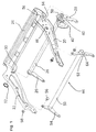
- eine perspektivische Darstellung eines Sitzträgers für ein Sitzgestell in Form eines Montagebildes und
- FIG. 2:
- eine Darstellung des Sitzträgers ähnlich Fig. 1, jedoch nicht als Montagebild, sondern in zusammengesetzter Form und mit zugeordneten Schienenpaaren einer Längsführung.
- FIG. 1:
- a perspective view of a seat support for a seat frame in the form of an assembly picture and
- FIG. 2:
- a representation of the seat support similar to FIG. 1, but not as an assembly picture, but in an assembled form and with associated pairs of rails of a longitudinal guide.
Wie aus Figur 1 und 2 ersichtlich ist, hat der Sitzträger ein linkes Seitenteil 20, ein
rechtes Seitenteil 22 und eine rückwärtige Traverse 24. Die Bezeichnungen links und
rechts sowie vorn und hinten werden immer im Bezug auf einen Passagier gesehen,
der auf dem Sitzträger Platz nimmt.As can be seen from FIGS. 1 and 2, the seat support has a
Weiterhin gehört zum Sitzträger eine rückwärtige Querwelle 26, an der ein linker und
ein rechter Stellarm 28 festgelegt sind, beispielsweise angeschweißt sind. Wie aus
Figur 1 ersichtlich, steht jenseits des rechten Stellarms 28 die Querwelle 26 frei vor, so
dass dieser freie Endbereich in eine Lagerbohrung 30 des rechten Seitenteils 22 eingesetzt
werden kann. Mittels des eingezeichneten Sicherungsringes 32 erfolgt die Fixierung.Furthermore, a
Das linke Seitenteil 20 hat eine Aufnahmebucht 34, die nach unten offen ist. Es sind
links und rechts der Aufnahmebucht 34 jeweils Löcher vorgesehen, die als erste Befestigungsmittel
36 bezeichnet werden. Um die Querwelle 26 ist ein Lagerteil 38 angeordnet,
das einerseits eine Lagerung der Querwelle 26 übernimmt und andererseits zweite
Befestigungsmittel 40 ausbildet, die auch hier als Löcher ausgeführt sind. Das Lagerteil
38 ist so ausgeführt, dass es die Aufnahmebucht 34 überbrückt und nach Befestigung
am zugehörigen, linken Seitenteil 20 die (eigentlich dort fehlende) Lagerbohrung für
den linken Bereich der Querwelle 26 ausbildet. Im gezeigten Ausführungsbeispiel befindet
sich das Lagerteil 38 nach der Montage auf der Innenseite des linken Seitenteils
20, also zwischen den beiden Seitenteilen 20, 22. Der linke Stellarm 28 befindet sich
dagegen auf der Außenseite des linken Seitenteils 20.The
Weiter inwärts auf der Querwelle 26, also vom Lagerteil 38 zum rechten Seitenteil 22
hingewandt ist ein Antriebsteil 42 mit der Querwelle 26 verbunden. Es ist in der konkreten
Ausbildung mit einem Zahnbogen versehen. Further inwards on the
Aus der Beschreibung wird verständlich, dass die Querwelle 26 mit ihren beiden Stellarmen
28, dem Lagerteil 38 und dem Antriebsteil 42 als Baueinheit komplett vorgefertigt
werden kann, die später, wie aus Figur 1 durch die strichpunktierte obere Montagelinie
ersichtlich ist, in die vorgefertigte Einheit aus den beiden Seitenteilen 20, 22 und
der rückwärtigen Traverse 24 eingefügt werden kann.From the description it is understood that the
Wie Figur 1 und 2 zeigen, ist die rückwärtige Traverse 24 an insgesamt vier Verbindungspunkten
mit den beiden Seitenteilen 20, 22 verbunden. Diese Verbindungspunkte
sind lösbar, beispielsweise erfolgen sie über Schraubenverbindungen.
Sie können auch durch entfernbare Niete realisiert sein. Ebenso kann die Verbindung
des Lagerteils 38 mit dem Randbereich der Aufnahmebucht 34 mittels der Befestigungsmittel
36, 40 über Schweißen, Vernieten, Schrauben oder dergleichen erfolgen.As FIGS. 1 and 2 show, the
Wie Figur 2 zeigt, können zwei unterschiedliche Traversen 24, 25 eingesetzt werden.
Die montiert dargestellte Traverse 24 ist eine normale Traverse. Sie hat in bekannter
Weise Halterungen für die Aufnahme von Sitzfedern, die nach vorn verlaufen. Sie sind
hier nicht dargestellt. Durch Lösen der vier Verbindungspunkte, die entsprechend ausgeführt
sind, kann die Traverse 24 ersetzt werden durch eine Traverse 25 mit Bügeln
für eine Isofix-Befestigung. Dies ist durch die vier zueinander parallelen, strichpunktierten
Montagelinien dargestellt. Die Traverse 25 unterscheidet sich mit Ausnahme der
zwei Isofix-Bügel nicht von der Traverse 24.As FIG. 2 shows, two
In Figur 1 und 2 ist noch eine vordere Schwenkbrücke 44 eingezeichnet. Sie besteht
aus einem Querrohr 50 und zwei Schwenkstützen 52, 54, die jeweils an ihrem oberen
Ende und an ihrem unteren Ende eine Lagerbohrung haben und etwa in ihrem Mittelbereich
durch das Querrohr 50 fest miteinander verbunden sind. Auch diese Einheit
kann vormontiert und nachträglich in die beschriebene Anordnung integriert werden,
wie dies ebenfalls anhand der zwei unteren strichpunktierten Montagelinien deutlich
wird. An den Endpunkten der beiden Montagelinien befinden sich jeweils Verbindungsmittel,
die hier als Schrauben 56 und Muttern 58 ausgeführt sind.A front
Wie die Figuren zeigen, ist die rechte Schwenkstütze 54 ein im wesentlichen ebenes
Blechstanzteil. Sie ist, wie aus Figur 2 ersichtlich ist, auf der Außenseite des rechten
Seitenteils 22 angeordnet. Im wesentlichen lotrecht unter ihr befindet sich ein rechtes
Schienenpaar 60 einer Längsführung. Dagegen ist die linke Schwenkstütze 52 stark
nach außen und nach unten ausgestellt, verläuft also schräg. Dies hat zur Folge, dass
ein zugehöriges, linkes Schienenpaar 62 sich in einer Entfernung d von einer Vertikalen
durch den Verbindungsbereich zwischen linker Schwenkstütze 42 und linkem Seitenteil
20 befindet, der auch als Versatz bezeichnet wird. Dieser Versatz d ist, wie ein Vergleich
mit der rechten Sitzseite zeigt, mindestens dreimal, vorzugsweise mindestens
fünfmal so groß wie auf der rechten Sitzseite.As the figures show, the
Die linke Schwenkstütze 52 verläuft in ihrem Verbindungsbereich mit dem Querrohr 50
schräg, man erkennt dies an der elliptisch verlaufenden Verbindungslinie. Dagegen
verläuft das Querrohr 50 praktisch rechtwinklig zur rechten Schwenkstütze 54, man
erkennt dies an der kreisförmigen Verbindungslinie.The
Die linke Schwenkstütze 52 hat eine Aussteifung 64 in Form eines im wesentlichen
dreieckförmigen Blechstücks, das bevorzugt einstückig mit der eigentlichen Schwenkstütze
52 zusammenhängt und aus ihrer Ebene herausgebogen ist, so dass es im wesentlichen
quer zur Bewegungsebene, in der die linke Schwenkstütze 52 um ihren Anlenkpunkt
am linken Seitenteil schwenkt, steht. Die Aussteifung 64 läuft nach unten
aus, sie ist oben, entlang einer Dreiecksseite, mit dem Querrohr 50 verbunden. Es ist
auch möglich, oberhalb des Querrohres eine entsprechende Aussteifung einzusetzen,
die aber hier nicht eingezeichnet ist.The
Im vorderen Endbereich der beiden Seitenteile 20, 22 sind jeweils zwei Löcher vorgesehen,
hier kann eine vordere Traverse (nicht dargestellt) angeordnet werden.Two holes are provided in the front end area of the two
Wie sich aus Figur 1 und 2 ergibt, sind die beiden Seitenteile 20, 22 im wesentlichen
spiegelbildlich baugleich, sie unterscheiden sich jedoch im Bereich der Lagerbohrung
30 bzw. der Aufnahmebucht 34. In Nähe der Aufnahmebucht 34 ist ein Loch im
Seitenteil 20 vorgesehen, das hier als Lager 46 ausgebildet ist. Um dieses Lager 46
sind mehrere Befestigungslöcher vorgesehen. Im Bereich um das Lager 46 kann ein
Elektromotor 48 angeflanscht werden. Er hat folgende Besonderheit: Sein Getriebegehäuse
ist in dem, dem Seitenteil 20 zugewandten Bereich offen, dort fehlt also eine
Gehäusewand des Getriebegehäuses. Das Seitenteil 20 übernimmt im Bereich um das
Lager 46 herum die Funktion der fehlenden Gehäusewand des Getriebegehäuses. Auf
diese Weise wird Gewicht gespart, es wird eine präzise Lagerung der Ausgangswelle
des Elektromotors 48 im Seitenteil 20 erreicht und die Zuordnung zum Antriebsteil 42
ist günstig.As can be seen from FIGS. 1 and 2, the two
Es ist auch möglich, anstelle eines Lagers direkt im linken Seitenteil 20 ein entsprechend
vergrößertes Lagerteil 38 einzusetzen, das zugleich auch noch die Lagerung der
Ausgangswelle des Elektromotors 48 und den Abschluß des Getriebegehäuses
übernimmt.It is also possible to place a bearing directly in the
Claims (8)
Applications Claiming Priority (2)
| Application Number | Priority Date | Filing Date | Title |
|---|---|---|---|
| DE29814223U DE29814223U1 (en) | 1998-02-27 | 1998-08-12 | Seat support frame of a vehicle seat with a left and a right front adjusting arm |
| DE29814223U | 1998-08-12 |
Publications (3)
| Publication Number | Publication Date |
|---|---|
| EP0979751A2 true EP0979751A2 (en) | 2000-02-16 |
| EP0979751A3 EP0979751A3 (en) | 2002-01-02 |
| EP0979751B1 EP0979751B1 (en) | 2005-11-09 |
Family
ID=8061033
Family Applications (1)
| Application Number | Title | Priority Date | Filing Date |
|---|---|---|---|
| EP99111912A Expired - Lifetime EP0979751B1 (en) | 1998-08-12 | 1999-06-21 | Vehicle seat support frame with left and right forward adjustment arms |
Country Status (3)
| Country | Link |
|---|---|
| US (1) | US6264274B1 (en) |
| EP (1) | EP0979751B1 (en) |
| DE (1) | DE59912756D1 (en) |
Cited By (2)
| Publication number | Priority date | Publication date | Assignee | Title |
|---|---|---|---|---|
| CN103702864A (en) * | 2011-07-26 | 2014-04-02 | C.劳勃.汉默斯坦两合有限公司 | Seat frame of a motor vehicle seat with two side parts and a transverse tube |
| US8888192B2 (en) | 2010-07-09 | 2014-11-18 | Toyota Boshoku Kabushiki Kaisha | Support structure of vehicle seat frame |
Families Citing this family (8)
| Publication number | Priority date | Publication date | Assignee | Title |
|---|---|---|---|---|
| DE10128670C1 (en) * | 2001-06-13 | 2002-06-20 | Faurecia Autositze Gmbh & Co | Releasable fixing device, for fitting child seat to a vehicle seat, has operating element on outside of vehicle seat by which torque is transmitted to turning axis |
| EP1291232B1 (en) | 2001-09-10 | 2006-11-15 | C.Rob. Hammerstein GmbH & Co.KG | Automotive vehicle seat frame with a seat support and front parallelogram arms |
| DE102007039363B4 (en) * | 2006-11-23 | 2015-03-19 | Johnson Controls Metals and Mechanisms GmbH & Co. KG | Adjustment device in a motor vehicle with a movable adjustment part and method for its production |
| JP2008173332A (en) * | 2007-01-19 | 2008-07-31 | Delta Tooling Co Ltd | Seat structure |
| WO2011027661A1 (en) * | 2009-09-04 | 2011-03-10 | Semiconductor Energy Laboratory Co., Ltd. | Light-emitting device and method for manufacturing the same |
| DE102010028630A1 (en) * | 2010-05-05 | 2011-11-10 | C. Rob. Hammerstein Gmbh & Co. Kg | Seat base for a motor vehicle seat |
| US9884684B2 (en) * | 2014-10-23 | 2018-02-06 | Gulfstream Aerospace Corporation | In-flight leveling system |
| JP6533247B2 (en) * | 2017-04-03 | 2019-06-19 | テイ・エス テック株式会社 | Vehicle seat |
Family Cites Families (8)
| Publication number | Priority date | Publication date | Assignee | Title |
|---|---|---|---|---|
| BE763001A (en) * | 1970-02-17 | 1971-07-16 | Chapman Ltd A W | VEHICLE SEAT SUPPORT |
| DE3046886A1 (en) * | 1980-12-12 | 1982-06-24 | Keiper Automobiltechnik Gmbh & Co Kg, 5630 Remscheid | HEIGHT ADJUSTMENT DEVICE FOR SEATS, IN PARTICULAR MOTOR VEHICLE SEATS |
| JP2910179B2 (en) * | 1990-07-26 | 1999-06-23 | アイシン精機株式会社 | Vertical adjustment device for vehicle seat |
| JP2995956B2 (en) * | 1991-10-18 | 1999-12-27 | トヨタ自動車株式会社 | Seat frame mounting structure |
| US5284381A (en) * | 1991-11-19 | 1994-02-08 | Tachi-S Co. Ltd. | Structure of seat cushion frame in automotive seat |
| FR2687353B1 (en) * | 1992-02-18 | 1998-02-13 | Renault | DEVICE FOR ADJUSTING THE HEIGHT OF A SEAT CUSHION SUPPORT. |
| FR2728206A1 (en) * | 1994-12-20 | 1996-06-21 | Faure Bertrand Equipements Sa | SEAT FRAME FOR VEHICLE SEAT |
| US5964441A (en) * | 1996-04-01 | 1999-10-12 | Lear Corporation | Linkage assembly with extruded hole member |
-
1999
- 1999-06-21 EP EP99111912A patent/EP0979751B1/en not_active Expired - Lifetime
- 1999-06-21 DE DE59912756T patent/DE59912756D1/en not_active Expired - Lifetime
- 1999-08-11 US US09/372,695 patent/US6264274B1/en not_active Expired - Lifetime
Non-Patent Citations (1)
| Title |
|---|
| None |
Cited By (4)
| Publication number | Priority date | Publication date | Assignee | Title |
|---|---|---|---|---|
| US8888192B2 (en) | 2010-07-09 | 2014-11-18 | Toyota Boshoku Kabushiki Kaisha | Support structure of vehicle seat frame |
| DE102011078688B4 (en) | 2010-07-09 | 2021-11-04 | Toyota Boshoku K.K. | SUPPORTING STRUCTURE FOR A VEHICLE SEAT FRAME |
| CN103702864A (en) * | 2011-07-26 | 2014-04-02 | C.劳勃.汉默斯坦两合有限公司 | Seat frame of a motor vehicle seat with two side parts and a transverse tube |
| CN103702864B (en) * | 2011-07-26 | 2017-04-19 | C.劳勃.汉默斯坦两合有限公司 | Seat frame of a motor vehicle seat with two side parts and a transverse tube |
Also Published As
| Publication number | Publication date |
|---|---|
| EP0979751B1 (en) | 2005-11-09 |
| EP0979751A3 (en) | 2002-01-02 |
| US6264274B1 (en) | 2001-07-24 |
| DE59912756D1 (en) | 2005-12-15 |
Similar Documents
| Publication | Publication Date | Title |
|---|---|---|
| DE29814223U1 (en) | Seat support frame of a vehicle seat with a left and a right front adjusting arm | |
| DE69600909T2 (en) | Backrest frame for vehicle seat | |
| DE10315056B4 (en) | Motor vehicle side threshold reinforcing structure | |
| DE19538229B4 (en) | Upper body structure for vehicle bodies | |
| EP2337704B1 (en) | Base frame of a vehicle seat comprising two pairs of rails, rockers and one seat support | |
| DE102006027390B4 (en) | Gooseneck joint arrangement for vehicles | |
| DE4408219A1 (en) | Adjustable vehicle seat | |
| EP0979752B1 (en) | Vehicle seat frame with a seat support with two side parts and a rear crossbar | |
| WO2013110528A1 (en) | Subframe for a motor vehicle | |
| DE102007041000B4 (en) | Motor vehicle with a base, a safety belt and a belt machine | |
| EP2054260A1 (en) | Vehicle seat, in particular commercial vehicle seat | |
| EP0979748B1 (en) | Seat frame for an adjustable vehicle seat | |
| EP0979751B1 (en) | Vehicle seat support frame with left and right forward adjustment arms | |
| WO2012045778A2 (en) | Longitudinal adjustment device for a motor vehicle seat | |
| EP2473393B1 (en) | Vehicle chassis having modular rear axle construction | |
| DE10310018A1 (en) | Device for fastening a belt buckle of a seat belt to a vehicle seat | |
| DE102005060480B4 (en) | Automotive seat | |
| DE10001102A1 (en) | Front bodywork for a motor vehicle | |
| DE102018106419B4 (en) | adjusting device | |
| DE102006060179A1 (en) | Seat for e.g. passenger car, has lateral part in shape of shell, having root and shaped flange, where diverted lateral part is opened on seat side located from exterior side of vehicle | |
| DE102013218993A1 (en) | seat adjustment | |
| DE19745032B4 (en) | Hinge assembly for the pivotable articulation of a door or tailgate on a body part of a motor vehicle | |
| DE102020122541A1 (en) | Vehicle seat support structure and vehicle seat | |
| DE102005024264B4 (en) | Body floor for motor vehicles | |
| DE102014207534B4 (en) | VEHICLE SEAT WITH ADJUSTMENT KINEMATICS |
Legal Events
| Date | Code | Title | Description |
|---|---|---|---|
| PUAI | Public reference made under article 153(3) epc to a published international application that has entered the european phase |
Free format text: ORIGINAL CODE: 0009012 |
|
| AK | Designated contracting states |
Kind code of ref document: A2 Designated state(s): AT BE CH CY DE DK ES FI FR GB GR IE IT LI LU MC NL PT SE Kind code of ref document: A2 Designated state(s): DE FR |
|
| AX | Request for extension of the european patent |
Free format text: AL;LT;LV;MK;RO;SI |
|
| PUAL | Search report despatched |
Free format text: ORIGINAL CODE: 0009013 |
|
| AK | Designated contracting states |
Kind code of ref document: A3 Designated state(s): AT BE CH CY DE DK ES FI FR GB GR IE IT LI LU MC NL PT SE |
|
| AX | Request for extension of the european patent |
Free format text: AL;LT;LV;MK;RO;SI |
|
| RIC1 | Information provided on ipc code assigned before grant |
Free format text: 7B 60N 2/28 A, 7B 60N 2/16 B, 7B 60N 2/07 B |
|
| 17P | Request for examination filed |
Effective date: 20020702 |
|
| AKX | Designation fees paid |
Free format text: DE FR |
|
| GRAP | Despatch of communication of intention to grant a patent |
Free format text: ORIGINAL CODE: EPIDOSNIGR1 |
|
| GRAS | Grant fee paid |
Free format text: ORIGINAL CODE: EPIDOSNIGR3 |
|
| GRAA | (expected) grant |
Free format text: ORIGINAL CODE: 0009210 |
|
| AK | Designated contracting states |
Kind code of ref document: B1 Designated state(s): DE FR |
|
| REF | Corresponds to: |
Ref document number: 59912756 Country of ref document: DE Date of ref document: 20051215 Kind code of ref document: P |
|
| ET | Fr: translation filed | ||
| PLBE | No opposition filed within time limit |
Free format text: ORIGINAL CODE: 0009261 |
|
| STAA | Information on the status of an ep patent application or granted ep patent |
Free format text: STATUS: NO OPPOSITION FILED WITHIN TIME LIMIT |
|
| 26N | No opposition filed |
Effective date: 20060810 |
|
| REG | Reference to a national code |
Ref country code: DE Ref legal event code: R082 Ref document number: 59912756 Country of ref document: DE Representative=s name: PATENTANWAELTE BAUER VORBERG KAYSER PARTNERSCH, DE |
|
| REG | Reference to a national code |
Ref country code: DE Ref legal event code: R082 Ref document number: 59912756 Country of ref document: DE Representative=s name: PATENTANWAELTE BAUER VORBERG KAYSER PARTNERSCH, DE Effective date: 20141016 Ref country code: DE Ref legal event code: R081 Ref document number: 59912756 Country of ref document: DE Owner name: JOHNSON CONTROLS METALS AND MECHANISMS GMBH & , DE Free format text: FORMER OWNER: C. ROB. HAMMERSTEIN GMBH & CO. KG, 42699 SOLINGEN, DE Effective date: 20141016 |
|
| PGFP | Annual fee paid to national office [announced via postgrant information from national office to epo] |
Ref country code: DE Payment date: 20150630 Year of fee payment: 17 |
|
| REG | Reference to a national code |
Ref country code: FR Ref legal event code: PLFP Year of fee payment: 18 |
|
| PGFP | Annual fee paid to national office [announced via postgrant information from national office to epo] |
Ref country code: FR Payment date: 20160627 Year of fee payment: 18 |
|
| REG | Reference to a national code |
Ref country code: DE Ref legal event code: R119 Ref document number: 59912756 Country of ref document: DE |
|
| PG25 | Lapsed in a contracting state [announced via postgrant information from national office to epo] |
Ref country code: DE Free format text: LAPSE BECAUSE OF NON-PAYMENT OF DUE FEES Effective date: 20170103 |
|
| REG | Reference to a national code |
Ref country code: FR Ref legal event code: ST Effective date: 20180228 |
|
| PG25 | Lapsed in a contracting state [announced via postgrant information from national office to epo] |
Ref country code: FR Free format text: LAPSE BECAUSE OF NON-PAYMENT OF DUE FEES Effective date: 20170630 |