EP0979636A2 - Femoral ligament tensing and prosthesis sizing device - Google Patents
Femoral ligament tensing and prosthesis sizing device Download PDFInfo
- Publication number
- EP0979636A2 EP0979636A2 EP99306323A EP99306323A EP0979636A2 EP 0979636 A2 EP0979636 A2 EP 0979636A2 EP 99306323 A EP99306323 A EP 99306323A EP 99306323 A EP99306323 A EP 99306323A EP 0979636 A2 EP0979636 A2 EP 0979636A2
- Authority
- EP
- European Patent Office
- Prior art keywords
- bone
- jack
- jig
- tool
- template
- Prior art date
- Legal status (The legal status is an assumption and is not a legal conclusion. Google has not performed a legal analysis and makes no representation as to the accuracy of the status listed.)
- Granted
Links
- 210000003041 ligament Anatomy 0.000 title claims abstract description 8
- 238000004513 sizing Methods 0.000 title abstract description 27
- 210000000988 bone and bone Anatomy 0.000 claims abstract description 51
- 210000004872 soft tissue Anatomy 0.000 claims abstract description 11
- 241001227561 Valgus Species 0.000 claims description 5
- 241000469816 Varus Species 0.000 claims description 5
- 238000001356 surgical procedure Methods 0.000 claims description 4
- 210000003127 knee Anatomy 0.000 abstract description 3
- 210000000689 upper leg Anatomy 0.000 description 30
- 238000000034 method Methods 0.000 description 5
- 210000002303 tibia Anatomy 0.000 description 5
- 210000004439 collateral ligament Anatomy 0.000 description 4
- 238000002271 resection Methods 0.000 description 4
- 239000007943 implant Substances 0.000 description 3
- 230000007935 neutral effect Effects 0.000 description 3
- 241001422033 Thestylus Species 0.000 description 2
- 230000000694 effects Effects 0.000 description 2
- 210000002414 leg Anatomy 0.000 description 2
- 238000012986 modification Methods 0.000 description 2
- 230000004048 modification Effects 0.000 description 2
- 210000003813 thumb Anatomy 0.000 description 2
- 206010023204 Joint dislocation Diseases 0.000 description 1
- 230000000712 assembly Effects 0.000 description 1
- 238000000429 assembly Methods 0.000 description 1
- 230000001186 cumulative effect Effects 0.000 description 1
- 201000010099 disease Diseases 0.000 description 1
- 208000037265 diseases, disorders, signs and symptoms Diseases 0.000 description 1
- 230000003028 elevating effect Effects 0.000 description 1
- 210000000629 knee joint Anatomy 0.000 description 1
- 238000013150 knee replacement Methods 0.000 description 1
- 238000005259 measurement Methods 0.000 description 1
- 210000004417 patella Anatomy 0.000 description 1
- 230000008447 perception Effects 0.000 description 1
- 125000006850 spacer group Chemical group 0.000 description 1
- 210000001519 tissue Anatomy 0.000 description 1
Images


Classifications
-
- A—HUMAN NECESSITIES
- A61—MEDICAL OR VETERINARY SCIENCE; HYGIENE
- A61F—FILTERS IMPLANTABLE INTO BLOOD VESSELS; PROSTHESES; DEVICES PROVIDING PATENCY TO, OR PREVENTING COLLAPSING OF, TUBULAR STRUCTURES OF THE BODY, e.g. STENTS; ORTHOPAEDIC, NURSING OR CONTRACEPTIVE DEVICES; FOMENTATION; TREATMENT OR PROTECTION OF EYES OR EARS; BANDAGES, DRESSINGS OR ABSORBENT PADS; FIRST-AID KITS
- A61F2/00—Filters implantable into blood vessels; Prostheses, i.e. artificial substitutes or replacements for parts of the body; Appliances for connecting them with the body; Devices providing patency to, or preventing collapsing of, tubular structures of the body, e.g. stents
- A61F2/02—Prostheses implantable into the body
- A61F2/30—Joints
- A61F2/46—Special tools for implanting artificial joints
- A61F2/4657—Measuring instruments used for implanting artificial joints
-
- A—HUMAN NECESSITIES
- A61—MEDICAL OR VETERINARY SCIENCE; HYGIENE
- A61B—DIAGNOSIS; SURGERY; IDENTIFICATION
- A61B17/00—Surgical instruments, devices or methods
- A61B17/14—Surgical saws
- A61B17/15—Guides therefor
- A61B17/154—Guides therefor for preparing bone for knee prosthesis
- A61B17/155—Cutting femur
-
- A—HUMAN NECESSITIES
- A61—MEDICAL OR VETERINARY SCIENCE; HYGIENE
- A61B—DIAGNOSIS; SURGERY; IDENTIFICATION
- A61B17/00—Surgical instruments, devices or methods
- A61B17/02—Surgical instruments, devices or methods for holding wounds open, e.g. retractors; Tractors
- A61B17/025—Joint distractors
-
- A—HUMAN NECESSITIES
- A61—MEDICAL OR VETERINARY SCIENCE; HYGIENE
- A61F—FILTERS IMPLANTABLE INTO BLOOD VESSELS; PROSTHESES; DEVICES PROVIDING PATENCY TO, OR PREVENTING COLLAPSING OF, TUBULAR STRUCTURES OF THE BODY, e.g. STENTS; ORTHOPAEDIC, NURSING OR CONTRACEPTIVE DEVICES; FOMENTATION; TREATMENT OR PROTECTION OF EYES OR EARS; BANDAGES, DRESSINGS OR ABSORBENT PADS; FIRST-AID KITS
- A61F2/00—Filters implantable into blood vessels; Prostheses, i.e. artificial substitutes or replacements for parts of the body; Appliances for connecting them with the body; Devices providing patency to, or preventing collapsing of, tubular structures of the body, e.g. stents
- A61F2/02—Prostheses implantable into the body
- A61F2/30—Joints
- A61F2/38—Joints for elbows or knees
- A61F2/3859—Femoral components
-
- A—HUMAN NECESSITIES
- A61—MEDICAL OR VETERINARY SCIENCE; HYGIENE
- A61F—FILTERS IMPLANTABLE INTO BLOOD VESSELS; PROSTHESES; DEVICES PROVIDING PATENCY TO, OR PREVENTING COLLAPSING OF, TUBULAR STRUCTURES OF THE BODY, e.g. STENTS; ORTHOPAEDIC, NURSING OR CONTRACEPTIVE DEVICES; FOMENTATION; TREATMENT OR PROTECTION OF EYES OR EARS; BANDAGES, DRESSINGS OR ABSORBENT PADS; FIRST-AID KITS
- A61F2/00—Filters implantable into blood vessels; Prostheses, i.e. artificial substitutes or replacements for parts of the body; Appliances for connecting them with the body; Devices providing patency to, or preventing collapsing of, tubular structures of the body, e.g. stents
- A61F2/02—Prostheses implantable into the body
- A61F2/30—Joints
- A61F2002/30001—Additional features of subject-matter classified in A61F2/28, A61F2/30 and subgroups thereof
- A61F2002/30316—The prosthesis having different structural features at different locations within the same prosthesis; Connections between prosthetic parts; Special structural features of bone or joint prostheses not otherwise provided for
- A61F2002/30535—Special structural features of bone or joint prostheses not otherwise provided for
- A61F2002/30537—Special structural features of bone or joint prostheses not otherwise provided for adjustable
- A61F2002/30546—Special structural features of bone or joint prostheses not otherwise provided for adjustable for adjusting elasticity, flexibility, spring rate or mechanical tension
-
- A—HUMAN NECESSITIES
- A61—MEDICAL OR VETERINARY SCIENCE; HYGIENE
- A61F—FILTERS IMPLANTABLE INTO BLOOD VESSELS; PROSTHESES; DEVICES PROVIDING PATENCY TO, OR PREVENTING COLLAPSING OF, TUBULAR STRUCTURES OF THE BODY, e.g. STENTS; ORTHOPAEDIC, NURSING OR CONTRACEPTIVE DEVICES; FOMENTATION; TREATMENT OR PROTECTION OF EYES OR EARS; BANDAGES, DRESSINGS OR ABSORBENT PADS; FIRST-AID KITS
- A61F2/00—Filters implantable into blood vessels; Prostheses, i.e. artificial substitutes or replacements for parts of the body; Appliances for connecting them with the body; Devices providing patency to, or preventing collapsing of, tubular structures of the body, e.g. stents
- A61F2/02—Prostheses implantable into the body
- A61F2/30—Joints
- A61F2/46—Special tools for implanting artificial joints
- A61F2/4657—Measuring instruments used for implanting artificial joints
- A61F2002/4658—Measuring instruments used for implanting artificial joints for measuring dimensions, e.g. length
-
- A—HUMAN NECESSITIES
- A61—MEDICAL OR VETERINARY SCIENCE; HYGIENE
- A61F—FILTERS IMPLANTABLE INTO BLOOD VESSELS; PROSTHESES; DEVICES PROVIDING PATENCY TO, OR PREVENTING COLLAPSING OF, TUBULAR STRUCTURES OF THE BODY, e.g. STENTS; ORTHOPAEDIC, NURSING OR CONTRACEPTIVE DEVICES; FOMENTATION; TREATMENT OR PROTECTION OF EYES OR EARS; BANDAGES, DRESSINGS OR ABSORBENT PADS; FIRST-AID KITS
- A61F2/00—Filters implantable into blood vessels; Prostheses, i.e. artificial substitutes or replacements for parts of the body; Appliances for connecting them with the body; Devices providing patency to, or preventing collapsing of, tubular structures of the body, e.g. stents
- A61F2/02—Prostheses implantable into the body
- A61F2/30—Joints
- A61F2/46—Special tools for implanting artificial joints
- A61F2/4657—Measuring instruments used for implanting artificial joints
- A61F2002/4666—Measuring instruments used for implanting artificial joints for measuring force, pressure or mechanical tension
-
- A—HUMAN NECESSITIES
- A61—MEDICAL OR VETERINARY SCIENCE; HYGIENE
- A61F—FILTERS IMPLANTABLE INTO BLOOD VESSELS; PROSTHESES; DEVICES PROVIDING PATENCY TO, OR PREVENTING COLLAPSING OF, TUBULAR STRUCTURES OF THE BODY, e.g. STENTS; ORTHOPAEDIC, NURSING OR CONTRACEPTIVE DEVICES; FOMENTATION; TREATMENT OR PROTECTION OF EYES OR EARS; BANDAGES, DRESSINGS OR ABSORBENT PADS; FIRST-AID KITS
- A61F2250/00—Special features of prostheses classified in groups A61F2/00 - A61F2/26 or A61F2/82 or A61F9/00 or A61F11/00 or subgroups thereof
- A61F2250/0004—Special features of prostheses classified in groups A61F2/00 - A61F2/26 or A61F2/82 or A61F9/00 or A61F11/00 or subgroups thereof adjustable
- A61F2250/0012—Special features of prostheses classified in groups A61F2/00 - A61F2/26 or A61F2/82 or A61F9/00 or A61F11/00 or subgroups thereof adjustable for adjusting elasticity, flexibility, spring rate or mechanical tension
Definitions
- the present invention relates to tools and jigs for laying out machine cuts to prepare a bone for receiving a correctly sized and aligned prosthetic component, such as prosthetic knee.
- the surgical preparation of bone endings for receiving prosthetic knee joints for a total knee replacement is generally a complex procedure, particularly when ligaments remain attached, or when osteoartbritic changes to the joint have distorted the normal, more symmetric articulation geometry of the joint or bone.
- a number of bone cuts are made to effect the placement and orientation of the femoral component of the prosthesis, and to determine and form the joint gaps in extension and flexion.
- the size and shape of these two gaps affect final orientation of the prosthesis, as well as joint tensioning and clearances.
- the flexion gap is related to internal/external orientation of the femur, while the extension gap is related to the varus/valgus orientation of the femur.
- these cuts are formed so that in extension the joint gap is perpendicular to the mechanical axis of the femur, while in flexion the joint gap is such as to place the femoral component in either neutral or external rotation and assure proper patellar tracking with the femoral component. Furthermore to fit the femoral component the gaps created by the bone resections in both flexion and extension should be rectangular.
- a tool in accordance with the present invention lays out resection or alignment features for prosthetic joint replacement.
- the tool rests on a resected end of one bone of an articulating joint set, and includes a jack for pivotally supporting an opposing bone of the set while the two bone ends remain attached together by ligaments.
- the jack raises the opposing bone in flexion to the spacing of the intended prosthesis to allow the surgeon to balance soft tissue tension.
- This support allows the bone to rotate under the tension of the connecting ligaments into natural alignment, so that a template carried by the jack assembly for initially laying out drill holes, a saw cut or the like, lies against the prepared end with the bone in that orientation, thereby assuring a correct rotational alignment of the machined bone when the joint components are attached.
- a sizing jig in the tool contacts the bone to determine an offset, and a positioning block coupled to the sizing jig positions drill holes on the bone surface contacted by the jig.
- the sizing jig may include a template for indicating the size of a required prosthetic joint component, as well as one or more accessories for confirming or adjusting the size indicated on the template with respect to other landmarks.
- the jack may lift a gimballed collar that fits about on intramedullary rod to support the bone, thus allowing the marking or fitting components to pivot to the appropriate varus/valgus plane.
- the drill holes may set a position for a standard cutting block to fit a femoral end component.
- the present invention is a tool which simplifies the procedure of preparing the distal femoral end for a prosthetic implant by allowing the surgeon to set soft tissue tension, size the femur, and size the flexion gap using a single instrument.
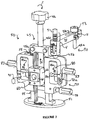
- the mechanical arrangement of various components of the tool in a prototype embodiment 50 will be appreciated from discussion of the figures below, illustrating its structure and operation.
- the tool is intended for use during surgery, and has a base 51 which rests on the proximal resected tibial cut 11 of a tibia 10 to support the femur 20.
- the tool is used once the surgeon has performed the proximal tibial cut, made the distal femoral cut, and freed up the collateral ligaments, so that the extension gap between the end faces of the tibia and femur which are to receive the prosthetic joint components has been set.
- this gap in extension is checked using sizing blocks, and is set for one representative system to be approximately 17 millimeters or greater; the spacing is set to accommodate the combined vertical thicknesses of the articulating femoral component, the tibial tray, and an insert having an upper articulation surface.
- the exposed bones are placed in flexion and the tool 50 is used to support the femur 20, with the base 51 of the tool set on the proximal resected tibial end 11, while a subassembly slides against the distal resected femoral end 21.
- the tool 50 supports the femur 20 on an intramedullary rod 44 which is raised or lowered by a jack assembly indicated generally by 45 while the surgeon adjusts the soft tissue tension in flexion.
- the femur 20 may pivot with the rod under the influence of tension of the medial and lateral ligaments, so that when soft tissue balancing is achieved, the bone will rotate into a natural position.
- Other portions of the tool carried by the jack assembly then cooperate to set marks or positioning features for attaching a conventional cutting block to then perform the posterior femoral cut, indicated schematically by dashed line 22 in the figure, which sets the flexion gap. Operation of the tool assures that the flexion gap so defined places the femoral component in either neutral or external rotation, thus assuring that proper patella tracking will occur. This operation will be more fully understood from a more detailed discussion of the tool and its structural features, a prototype embodiment of which is illustrated in Figure 3.
- the tool 50 includes a jack assembly 45 which extends upward from a base or support plate 51.
- the jack assembly moves a lifting carriage 60 between two support posts 45a, 45b along a vertical direction, while a sizing block 70 is configured to be manually moved up and down the support posts of the jack assembly.
- the lifting carriage 60 lifts the intramedullary rod 40 to set the height of the femur, and the sizing block 70 slides along the same axis so that it may be readily aligned with the femur at the distal end.
- a positioning template 80 including first and second drill guide blocks 81, 82 which are rigidly connected to each other by a thin bridge plate 86 (shown in Figure 6) slide up and down as a unit against the distal femoral surface to position the drill guides 81a, 82a respectively.
- the drill guide or template 80 may be locked in position within the sizing block 70 by locking thumb screws 83.
- the guide or template 80 connects to a preferably removable cortex hook assembly 90 comprising a vertical post 91 which rotates about its axis in a pair or aligned support holes (not numbered) in the sizing block 70 and drill guide 80, and carries a vertically adjustable positioning arm 92 to position a pin 93 against the anterior femoral cortex.
- the positioning arm 92 slides up and down with detents on the post 91 to indicate (as a component size) the vertical height of the femoral surface, and stylus 93 slides back and forth in a slot 92a of the arm to position its tip 93a behind the condyles on the surface of the femur.
- Corresponding size markings are graduated on each of posts 91 and arm 92 to show the size of the femur.
- graduations for the available femur articulation components appear on the sizing block 70 at regions 72.
- the graduated readings of assembly 90 confirm or indicate a discrepancy with the size set on the sizing block 70, and thus allow the size to be adjusted as the assembly is positioned.
- the tensioning and sizing device of Figure 3 is used during a surgical procedure as follows. First the tibial plateau and distal femur are resected and preliminary soft tissue balancing is carried out. The size of the gap between opposed resected bone endings is assessed with the leg in extension using spacer blocks which correspond to the specific tibial insert thicknesses which are to be used. Then, with the knee in 90° flexion, the support base 51 of the tool is placed on the resected tibial surface, and an intramedullary rod 40 is inserted into the intramedullary canal of the femur, and through the horizontal bore in the carriage 60.
- the lifting carriage 60 receives the intramedullary rod 40 in a block 61 which is mounted to pivot about a vertical axis by pin 62 so that the face plane of the entire assembly, i.e. the vertically-disposed plane on tile side opposite to that illustrated of the sizing block drill guide, may rest flush against the resected distal femur with which the rod makes the appropriate varus/valgus angle.
- the rod centrally supported by the gimballed holding block 61, turning the top knob 45c rotates the jack screw 45d and lifts the carriage 60, thus elevating the gimballed carrier so as to spread the tibia from the femur and tense the collateral ligaments.
- the femur size is set next, by sliding the drill guide 80 vertically within the sizing block 70 to line up wit one of the markings 72a, 72b on the front (anterior) face of the sizing block 70 corresponding to the specific femoral component sizes. This may be set to an initial or estimated size.
- the guide is locked into place by tightening two thumb screws 83 when the graduation reads the desired implant size.
- An adjustable stylus assembly 90 having components 91, 92, 93 is placed into the drill guide and through the sizing block, and is used to check the fit of the chosen implant size.
- a post 91 supports an arm 92 in which a stylus 93 is adjustably positioned to contact the anterior surface of the femur.
- the dimensions of post 91 and positioning arm 92 are such that this same size will be read off on the vertical and horizontal graduation scales of that assembly when the tip 93a of the stylus just touches the anterior cortex of the femur. If this is not the case, then a different size prosthesis may be considered to assure a better fit, and the guide 80 may be re-set accordingly.
- holes are drilled into the distal resected femur using the drill positioning guide holes 81a, 82a. The device is then removed and surgical technique proceeds using standard A/P resection blocks pinned in the two drill holes so made.
- the tensioning tool of the present invention allows the surgeon to conveniently adjust the soft tissue tension in flexion while sizing the femur and determining the cutting block position.
- the jack assembly supports the sizing block flush against the end of the femur and checks the prosthesis size in two dimensions against the anterior cortex.
- Figure 4 is a frontal plan view, more clearly showing the various sets of graduations. These are used for setting the tissue balancing flexion gap with graduations 55, setting the femoral component size wit the drill guide positioning template 80 and graduations 84, 72a and 72b confirming the size with the vertical and horizontal graduations V, H of the A/P positioning cortex hook assembly.
- Figure 5 is a top view more clearly illustrating the pivot range of adjustment to accommodate the orientation of the intramedullary rod, e.g. femoral axis, with respect to the other components of the tool, showing varus/valgus angle.
- the intramedullary rod e.g. femoral axis
- Figure 6 is a side plan view, illustrating the stylus tip 93a, the intramedullary rod 40, and the bridge plate 86 of the drill guide assembly (which rests against the plane "P" of the femoral end face) showing the spatial relation of these different sizing and positioning assemblies 70, 80 against the distal femur resected surface.
- the present invention advantageously provides a table or base which jacks up a carriage to support the intramedullary rod. This allows for a flexible extension of the femur, and permits several practical adjustments to be carried out with enhanced control or perception of the tensioning and positioning of necessary components.
Landscapes
- Health & Medical Sciences (AREA)
- Life Sciences & Earth Sciences (AREA)
- Orthopedic Medicine & Surgery (AREA)
- Transplantation (AREA)
- Surgery (AREA)
- Engineering & Computer Science (AREA)
- General Health & Medical Sciences (AREA)
- Nuclear Medicine, Radiotherapy & Molecular Imaging (AREA)
- Veterinary Medicine (AREA)
- Oral & Maxillofacial Surgery (AREA)
- Physical Education & Sports Medicine (AREA)
- Biomedical Technology (AREA)
- Heart & Thoracic Surgery (AREA)
- Public Health (AREA)
- Animal Behavior & Ethology (AREA)
- Biophysics (AREA)
- Vascular Medicine (AREA)
- Cardiology (AREA)
- Dentistry (AREA)
- Medical Informatics (AREA)
- Molecular Biology (AREA)
- Prostheses (AREA)
- Surgical Instruments (AREA)
Abstract
Description
Claims (6)
- A tool for prosthetic joint replacement surgery, such tool comprisinga jack for supporting a bone of an articulating set of bones to which a prosthetic end component is to be fastened at a respective end of said bone as it remains attached by ligaments to an opposed bone of said set, said jack raising said bone to permit the surgeon to adjust soft tissue tension in flexion, and pivotally supporting said bone such that said bone rotates due to tension of said ligaments, anda jig including a template for placing an aligned mark to prepare said bone for fastening the prosthetic end componentsaid jack cooperating with said jig to position the template while the bone has rotated into natural alignment, thereby assuring a correct rotational alignment of the bone when prosthetic end component is attached.
- A tool according to claim 1, wherein the jig includes a drill guide for positioning drill holes in an end surface of the bone to secure a cutting block.
- A tool according to claim 1, wherein the jig and jack cooperate to indicate size of the component.
- A tool according to claim 1, wherein the jack supports the bone on an intramedullary rod such that the bone rotates about its longitudinal axis.
- A tool according to claim 4, wherein the jig marks an orientation or position of a saw cut plate for fitting a femoral end component.
- A tool according to claim 4, wherein the jack varies height of a gimballed assembly, and the gimballed assembly engages the intramedullary rod to support the bone, thereby allowing the bone to assume a natural varus/valgus orientation.
Applications Claiming Priority (2)
| Application Number | Priority Date | Filing Date | Title |
|---|---|---|---|
| US09/132,279 US6056756A (en) | 1998-08-11 | 1998-08-11 | Femoral tensing and sizing device |
| US132279 | 1998-08-11 |
Publications (3)
| Publication Number | Publication Date |
|---|---|
| EP0979636A2 true EP0979636A2 (en) | 2000-02-16 |
| EP0979636A3 EP0979636A3 (en) | 2000-06-14 |
| EP0979636B1 EP0979636B1 (en) | 2009-04-29 |
Family
ID=22453272
Family Applications (1)
| Application Number | Title | Priority Date | Filing Date |
|---|---|---|---|
| EP99306323A Expired - Lifetime EP0979636B1 (en) | 1998-08-11 | 1999-08-10 | Femoral ligament tensing and prosthesis sizing device |
Country Status (4)
| Country | Link |
|---|---|
| US (1) | US6056756A (en) |
| EP (1) | EP0979636B1 (en) |
| JP (1) | JP4443680B2 (en) |
| DE (1) | DE69940798D1 (en) |
Cited By (31)
| Publication number | Priority date | Publication date | Assignee | Title |
|---|---|---|---|---|
| WO2002017826A1 (en) * | 2000-08-19 | 2002-03-07 | Biomet Merck Gbmh | Device for optimizing a knee endoprosthesis |
| EP1304093A1 (en) * | 2001-10-22 | 2003-04-23 | Sofinordest, S.A.S. | Method for measuring the balance of ligaments and ancillary for preparing the implantation of a knee prosthesis |
| WO2003079940A3 (en) * | 2002-03-19 | 2004-04-08 | Univ Illinois | System and method for prosthetic fitting and balancing in joints |
| FR2856274A1 (en) * | 2003-06-18 | 2004-12-24 | Perception Raisonnement Action | BONE CUTTING GUIDE POSITIONING DEVICE |
| EP1491166A1 (en) * | 2003-09-15 | 2004-12-29 | Zimmer GmbH | Adjusting device |
| FR2866556A1 (en) * | 2004-02-23 | 2005-08-26 | Sofinordest | Femoral and/or tibial plane selection assistance device for knee prosthesis preparation, has measuring unit including sensors measuring force exerted on arms related to desmoid tension of inner and outer ligaments |
| EP1402857A3 (en) * | 2002-09-30 | 2005-10-26 | Depuy Products, Inc. | System for tension assessment during joint arthroplasty |
| WO2007036699A1 (en) | 2005-09-30 | 2007-04-05 | Depuy International Limited | A distractor instrument |
| WO2007036694A1 (en) | 2005-09-30 | 2007-04-05 | Depuy International Limited | Instrument assembly for use in knee joint replacement surgery |
| EP1986555A4 (en) * | 2006-02-08 | 2010-10-20 | G Lynn Rasmussen | GUIDE ASSEMBLY FOR GUIDING DECOUPES ON A FEMUR AND TIBIA DURING KNEE ARTHROPLASTY |
| GB2482702A (en) * | 2010-08-11 | 2012-02-15 | Biomet Uk Healthcare Ltd | Ligament balancer |
| WO2012156806A1 (en) * | 2011-05-17 | 2012-11-22 | Medacta International S.A. | Surgical guide for implanting a knee prosthesis |
| EP2567665A3 (en) * | 2004-02-06 | 2013-06-19 | Synvasive Technology, Inc. | Dynamic knee balancer |
| US8597210B2 (en) | 2009-03-31 | 2013-12-03 | Depuy (Ireland) | System and method for displaying joint force data |
| WO2014006360A1 (en) * | 2012-07-04 | 2014-01-09 | Depuy (Ireland) | A measuring instrument for use in orthopaedic surgery |
| US8656790B2 (en) | 2006-03-29 | 2014-02-25 | Farid Amirouche | Device and method of spacer and trial design during joint arthroplasty |
| US8676778B2 (en) | 1995-12-14 | 2014-03-18 | Graphon Corporation | Method and apparatus for electronically publishing information on a computer network |
| US8721568B2 (en) | 2009-03-31 | 2014-05-13 | Depuy (Ireland) | Method for performing an orthopaedic surgical procedure |
| EP2442736A4 (en) * | 2009-06-19 | 2014-05-21 | Wright Medical Technologies Inc | CALIBRATION INSTRUMENT FOR TRACKING WITH RESPECT TO THE MEDIA LINE |
| US8740817B2 (en) | 2009-03-31 | 2014-06-03 | Depuy (Ireland) | Device and method for determining forces of a patient's joint |
| US8758355B2 (en) | 2004-02-06 | 2014-06-24 | Synvasive Technology, Inc. | Dynamic knee balancer with pressure sensing |
| US8876831B2 (en) | 2005-02-08 | 2014-11-04 | G. Lynn Rasmussen | Arthroplasty systems and methods for optimally aligning and tensioning a knee prosthesis |
| US9492179B2 (en) | 2005-02-08 | 2016-11-15 | Otsuka Medical Co., Ltd. | Systems and methods for guiding cuts to a femur and tibia during a knee arthroplasty |
| US9538953B2 (en) | 2009-03-31 | 2017-01-10 | Depuy Ireland Unlimited Company | Device and method for determining force of a knee joint |
| US10070973B2 (en) | 2012-03-31 | 2018-09-11 | Depuy Ireland Unlimited Company | Orthopaedic sensor module and system for determining joint forces of a patient's knee joint |
| US10485530B2 (en) | 2012-03-29 | 2019-11-26 | Depuy Ireland Unlimited Company | Orthopedic surgical instrument for knee surgery |
| CN114305576A (en) * | 2022-01-17 | 2022-04-12 | 王迎光 | Amputation device |
| US11357644B2 (en) | 2011-10-24 | 2022-06-14 | Synvasive Technology, Inc. | Knee balancing devices, systems and methods |
| US11992230B2 (en) | 2016-11-30 | 2024-05-28 | G. Lynn Rasmussen | Systems and methods for providing a tibial baseplate |
| US12414862B2 (en) | 2016-11-30 | 2025-09-16 | G. Lynn Rasmussen | Systems and methods for providing a tibial baseplate system |
| US12575818B2 (en) | 2005-02-08 | 2026-03-17 | G. Lynn Rasmussen | Arthroplasty systems and methods for optimally aligning and tensioning a knee prosthesis |
Families Citing this family (142)
| Publication number | Priority date | Publication date | Assignee | Title |
|---|---|---|---|---|
| US7534263B2 (en) | 2001-05-25 | 2009-05-19 | Conformis, Inc. | Surgical tools facilitating increased accuracy, speed and simplicity in performing joint arthroplasty |
| US7468075B2 (en) | 2001-05-25 | 2008-12-23 | Conformis, Inc. | Methods and compositions for articular repair |
| US8083745B2 (en) * | 2001-05-25 | 2011-12-27 | Conformis, Inc. | Surgical tools for arthroplasty |
| US7618451B2 (en) * | 2001-05-25 | 2009-11-17 | Conformis, Inc. | Patient selectable joint arthroplasty devices and surgical tools facilitating increased accuracy, speed and simplicity in performing total and partial joint arthroplasty |
| US6258095B1 (en) * | 1998-03-28 | 2001-07-10 | Stryker Technologies Corporation | Methods and tools for femoral intermedullary revision surgery |
| WO2000035346A2 (en) | 1998-09-14 | 2000-06-22 | Stanford University | Assessing the condition of a joint and preventing damage |
| US7239908B1 (en) | 1998-09-14 | 2007-07-03 | The Board Of Trustees Of The Leland Stanford Junior University | Assessing the condition of a joint and devising treatment |
| US9289153B2 (en) * | 1998-09-14 | 2016-03-22 | The Board Of Trustees Of The Leland Stanford Junior University | Joint and cartilage diagnosis, assessment and modeling |
| US7635390B1 (en) | 2000-01-14 | 2009-12-22 | Marctec, Llc | Joint replacement component having a modular articulating surface |
| EP2036495A1 (en) | 2000-09-14 | 2009-03-18 | The Board of Trustees of The Leland Stanford Junior University | Assessing condition of a joint and cartilage loss |
| AU9088801A (en) | 2000-09-14 | 2002-03-26 | Univ Leland Stanford Junior | Assessing the condition of a joint and devising treatment |
| US6458135B1 (en) * | 2001-02-02 | 2002-10-01 | Howmedica Osteonics Corp. | Femoral guide for implanting a femoral knee prosthesis and method |
| US7547307B2 (en) * | 2001-02-27 | 2009-06-16 | Smith & Nephew, Inc. | Computer assisted knee arthroplasty instrumentation, systems, and processes |
| US8439926B2 (en) | 2001-05-25 | 2013-05-14 | Conformis, Inc. | Patient selectable joint arthroplasty devices and surgical tools |
| WO2002096268A2 (en) | 2001-05-25 | 2002-12-05 | Imaging Therapeutics, Inc. | Methods and compositions for articular resurfacing |
| US8951260B2 (en) | 2001-05-25 | 2015-02-10 | Conformis, Inc. | Surgical cutting guide |
| US6482209B1 (en) * | 2001-06-14 | 2002-11-19 | Gerard A. Engh | Apparatus and method for sculpting the surface of a joint |
| US6723102B2 (en) | 2001-06-14 | 2004-04-20 | Alexandria Research Technologies, Llc | Apparatus and method for minimally invasive total joint replacement |
| US6855150B1 (en) | 2001-07-13 | 2005-02-15 | Timothy R. Linehan | Patellar trial and drill guide for use in knee replacement surgery |
| US7715602B2 (en) * | 2002-01-18 | 2010-05-11 | Orthosoft Inc. | Method and apparatus for reconstructing bone surfaces during surgery |
| US6916325B2 (en) * | 2002-02-11 | 2005-07-12 | Zimmer Orthobiologies, Inc. | Femoral sizing guide |
| US7237556B2 (en) | 2002-02-11 | 2007-07-03 | Smith & Nephew, Inc. | Image-guided fracture reduction |
| US20030187511A1 (en) * | 2002-03-26 | 2003-10-02 | Ball Robert J. | Wrist prosthesis |
| US6758850B2 (en) | 2002-03-29 | 2004-07-06 | Depuy Orthopaedics, Inc. | Instruments and methods for flexion gap adjustment |
| AU2003221664A1 (en) * | 2002-04-30 | 2003-11-17 | Orthosoft Inc. | Determining femoral cuts in knee surgery |
| US20040039396A1 (en) * | 2002-08-23 | 2004-02-26 | Orthosoft Inc. | Universal positioning block |
| US7736368B2 (en) * | 2002-08-23 | 2010-06-15 | Orthosoft Inc. | Surgical universal positioning block and tool guide |
| US20040097951A1 (en) * | 2002-11-18 | 2004-05-20 | Steffensmeier Scott J. | Measurement instrument for use in orthopaedic surgery |
| US20070282347A9 (en) * | 2002-12-20 | 2007-12-06 | Grimm James E | Navigated orthopaedic guide and method |
| US20040172044A1 (en) * | 2002-12-20 | 2004-09-02 | Grimm James E. | Surgical instrument and method of positioning same |
| US7887542B2 (en) | 2003-01-15 | 2011-02-15 | Biomet Manufacturing Corp. | Method and apparatus for less invasive knee resection |
| US8551100B2 (en) | 2003-01-15 | 2013-10-08 | Biomet Manufacturing, Llc | Instrumentation for knee resection |
| US7011664B2 (en) * | 2003-01-31 | 2006-03-14 | Zimmer Technology, Inc. | Resection guide alignment apparatus |
| US7111401B2 (en) * | 2003-02-04 | 2006-09-26 | Eveready Battery Company, Inc. | Razor head having skin controlling means |
| JP4231813B2 (en) * | 2003-05-06 | 2009-03-04 | ツィマー ゲーエムベーハー | Traction equipment |
| US7559931B2 (en) * | 2003-06-09 | 2009-07-14 | OrthAlign, Inc. | Surgical orientation system and method |
| US8057482B2 (en) | 2003-06-09 | 2011-11-15 | OrthAlign, Inc. | Surgical orientation device and method |
| EP1643917A1 (en) * | 2003-07-14 | 2006-04-12 | SYNTHES AG Chur | Aiming device |
| FR2857576B1 (en) * | 2003-07-16 | 2005-10-14 | Depuy France | ASSISTING DEVICE FOR THE IMPLANTATION OF TOTAL KNEE PROSTHESES |
| US7862570B2 (en) | 2003-10-03 | 2011-01-04 | Smith & Nephew, Inc. | Surgical positioners |
| US7764985B2 (en) | 2003-10-20 | 2010-07-27 | Smith & Nephew, Inc. | Surgical navigation system component fault interfaces and related processes |
| US7261719B1 (en) * | 2003-11-04 | 2007-08-28 | Biomet Manufacturing Corp. | Femoral sizing apparatus and method |
| CA2546023C (en) | 2003-11-14 | 2012-11-06 | Smith & Nephew, Inc. | Adjustable surgical cutting systems |
| US7488324B1 (en) | 2003-12-08 | 2009-02-10 | Biomet Manufacturing Corporation | Femoral guide for implanting a femoral knee prosthesis |
| US7442196B2 (en) * | 2004-02-06 | 2008-10-28 | Synvasive Technology, Inc. | Dynamic knee balancer |
| US8114086B2 (en) * | 2004-03-08 | 2012-02-14 | Zimmer Technology, Inc. | Navigated cut guide locator |
| US7993341B2 (en) | 2004-03-08 | 2011-08-09 | Zimmer Technology, Inc. | Navigated orthopaedic guide and method |
| JP2007531596A (en) | 2004-03-31 | 2007-11-08 | スミス アンド ネフュー インコーポレーテッド | Method and apparatus for providing a reference array input device |
| WO2005104978A1 (en) | 2004-04-21 | 2005-11-10 | Smith & Nephew, Inc. | Computer-aided methods, systems, and apparatuses for shoulder arthroplasty |
| US7662156B2 (en) * | 2004-06-22 | 2010-02-16 | Smith & Nephew, Inc. | Systems and processes for determining proper superior-inferior joint line positioning |
| US7963968B2 (en) * | 2004-12-21 | 2011-06-21 | Smith & Nephew, Inc. | Distal femoral trial with removable cutting guide |
| US20060155381A1 (en) * | 2005-01-07 | 2006-07-13 | Orthopaedic Development, Llc | Orthopedic system for total hip replacement surgery |
| US20060155382A1 (en) * | 2005-01-07 | 2006-07-13 | Orthopaedic Development, Llc. | Canulized prosthesis for total hip replacement surgery |
| CA2601976A1 (en) | 2005-02-22 | 2006-08-31 | Smith & Nephew, Inc. | In-line milling system |
| US7628794B2 (en) * | 2005-04-06 | 2009-12-08 | Trigon Inc. | Prosthetic revision knee system |
| US7695479B1 (en) | 2005-04-12 | 2010-04-13 | Biomet Manufacturing Corp. | Femoral sizer |
| US7909825B2 (en) | 2006-11-22 | 2011-03-22 | Sonoma Orthepedic Products, Inc. | Fracture fixation device, tools and methods |
| US9060820B2 (en) | 2005-05-18 | 2015-06-23 | Sonoma Orthopedic Products, Inc. | Segmented intramedullary fracture fixation devices and methods |
| US8287539B2 (en) | 2005-05-18 | 2012-10-16 | Sonoma Orthopedic Products, Inc. | Fracture fixation device, tools and methods |
| US8961516B2 (en) | 2005-05-18 | 2015-02-24 | Sonoma Orthopedic Products, Inc. | Straight intramedullary fracture fixation devices and methods |
| CN101208053A (en) | 2005-05-18 | 2008-06-25 | 索诺玛整形外科产品公司 | Minimally invasive actuatable bone fixation devices, systems and methods of use |
| DE102005049851A1 (en) * | 2005-10-18 | 2007-04-26 | Plus Orthopedics Ag | StrapsTie device |
| US20070149977A1 (en) * | 2005-11-28 | 2007-06-28 | Zimmer Technology, Inc. | Surgical component positioner |
| GB0526385D0 (en) * | 2005-12-28 | 2006-02-08 | Mcminn Derek J W | Improvements in or relating to knee prosthesis |
| US7520880B2 (en) | 2006-01-09 | 2009-04-21 | Zimmer Technology, Inc. | Adjustable surgical support base with integral hinge |
| US7744600B2 (en) * | 2006-01-10 | 2010-06-29 | Zimmer Technology, Inc. | Bone resection guide and method |
| JP2009529354A (en) | 2006-02-06 | 2009-08-20 | コンフォーミス, インコーポレイテッド | Patient-selectable arthroplasty device and surgical tool |
| US8623026B2 (en) | 2006-02-06 | 2014-01-07 | Conformis, Inc. | Patient selectable joint arthroplasty devices and surgical tools incorporating anatomical relief |
| US8070752B2 (en) | 2006-02-27 | 2011-12-06 | Biomet Manufacturing Corp. | Patient specific alignment guide and inter-operative adjustment |
| US20150335438A1 (en) | 2006-02-27 | 2015-11-26 | Biomet Manufacturing, Llc. | Patient-specific augments |
| US9345548B2 (en) | 2006-02-27 | 2016-05-24 | Biomet Manufacturing, Llc | Patient-specific pre-operative planning |
| US9113971B2 (en) | 2006-02-27 | 2015-08-25 | Biomet Manufacturing, Llc | Femoral acetabular impingement guide |
| US10278711B2 (en) | 2006-02-27 | 2019-05-07 | Biomet Manufacturing, Llc | Patient-specific femoral guide |
| US9289253B2 (en) | 2006-02-27 | 2016-03-22 | Biomet Manufacturing, Llc | Patient-specific shoulder guide |
| US8591516B2 (en) | 2006-02-27 | 2013-11-26 | Biomet Manufacturing, Llc | Patient-specific orthopedic instruments |
| US9173661B2 (en) | 2006-02-27 | 2015-11-03 | Biomet Manufacturing, Llc | Patient specific alignment guide with cutting surface and laser indicator |
| US8407067B2 (en) | 2007-04-17 | 2013-03-26 | Biomet Manufacturing Corp. | Method and apparatus for manufacturing an implant |
| US9339278B2 (en) | 2006-02-27 | 2016-05-17 | Biomet Manufacturing, Llc | Patient-specific acetabular guides and associated instruments |
| US8603180B2 (en) | 2006-02-27 | 2013-12-10 | Biomet Manufacturing, Llc | Patient-specific acetabular alignment guides |
| US9918740B2 (en) | 2006-02-27 | 2018-03-20 | Biomet Manufacturing, Llc | Backup surgical instrument system and method |
| US7780672B2 (en) | 2006-02-27 | 2010-08-24 | Biomet Manufacturing Corp. | Femoral adjustment device and associated method |
| US9907659B2 (en) | 2007-04-17 | 2018-03-06 | Biomet Manufacturing, Llc | Method and apparatus for manufacturing an implant |
| US9155574B2 (en) | 2006-05-17 | 2015-10-13 | Sonoma Orthopedic Products, Inc. | Bone fixation device, tools and methods |
| US9795399B2 (en) | 2006-06-09 | 2017-10-24 | Biomet Manufacturing, Llc | Patient-specific knee alignment guide and associated method |
| US7686812B2 (en) * | 2006-06-30 | 2010-03-30 | Howmedica Osteonics Corp. | Method for setting the rotational position of a femoral component |
| US8187280B2 (en) * | 2007-10-10 | 2012-05-29 | Biomet Manufacturing Corp. | Knee joint prosthesis system and method for implantation |
| US8265949B2 (en) | 2007-09-27 | 2012-09-11 | Depuy Products, Inc. | Customized patient surgical plan |
| ES2556909T3 (en) | 2007-09-30 | 2016-01-20 | Depuy Products, Inc. | Personalized and patient-specific orthopedic surgery instruments |
| US8357111B2 (en) | 2007-09-30 | 2013-01-22 | Depuy Products, Inc. | Method and system for designing patient-specific orthopaedic surgical instruments |
| US8197489B2 (en) | 2008-06-27 | 2012-06-12 | Depuy Products, Inc. | Knee ligament balancer |
| EP2344078B1 (en) | 2008-07-24 | 2018-04-18 | OrthAlign, Inc. | Systems for joint replacement |
| WO2010030809A1 (en) | 2008-09-10 | 2010-03-18 | Orthalign, Inc | Hip surgery systems and methods |
| US8808297B2 (en) | 2009-02-24 | 2014-08-19 | Microport Orthopedics Holdings Inc. | Orthopedic surgical guide |
| US9017334B2 (en) | 2009-02-24 | 2015-04-28 | Microport Orthopedics Holdings Inc. | Patient specific surgical guide locator and mount |
| US12383287B2 (en) | 2009-02-24 | 2025-08-12 | Microport Orthopedics Holdings, Inc. | Systems and methods for installing an orthopedic implant |
| US8808303B2 (en) | 2009-02-24 | 2014-08-19 | Microport Orthopedics Holdings Inc. | Orthopedic surgical guide |
| US8828012B2 (en) * | 2009-03-02 | 2014-09-09 | Zimmer, Inc. | Anterior cortex referencing extramedullary femoral cut guide |
| US8556830B2 (en) | 2009-03-31 | 2013-10-15 | Depuy | Device and method for displaying joint force data |
| BRPI1014917A2 (en) | 2009-04-16 | 2016-04-19 | Conformis Inc | "Patient specific joint arthroplasty devices for ligament repair" |
| US20100292705A1 (en) * | 2009-05-13 | 2010-11-18 | Maxx Orthopedics, Inc. | Sizing Guide for Femoral Prosthesis |
| GB0909918D0 (en) | 2009-06-09 | 2009-07-22 | Depuy Ireland | A femoral sizing instrument |
| US8118815B2 (en) | 2009-07-24 | 2012-02-21 | OrthAlign, Inc. | Systems and methods for joint replacement |
| US10869771B2 (en) | 2009-07-24 | 2020-12-22 | OrthAlign, Inc. | Systems and methods for joint replacement |
| CA2778040A1 (en) * | 2009-10-23 | 2011-04-28 | Synvasive Technology, Inc. | Knee balancing for revision procedures |
| WO2012082164A1 (en) * | 2010-01-21 | 2012-06-21 | Orthallgn, Inc. | Systems and methods for joint replacement |
| US9968376B2 (en) | 2010-11-29 | 2018-05-15 | Biomet Manufacturing, Llc | Patient-specific orthopedic instruments |
| US8672946B2 (en) | 2011-02-11 | 2014-03-18 | Biomet Manfacturing, LLC | Method and apparatus for performing knee arthroplasty |
| US9241745B2 (en) | 2011-03-07 | 2016-01-26 | Biomet Manufacturing, Llc | Patient-specific femoral version guide |
| EP3326542B1 (en) * | 2011-07-19 | 2019-09-25 | Zimmer, Inc. | Knee arthroplasty instrument |
| GB201115411D0 (en) | 2011-09-07 | 2011-10-19 | Depuy Ireland | Surgical instrument |
| CA2854997A1 (en) * | 2011-11-11 | 2013-05-16 | Depuy (Ireland) | A bone sizing guide |
| US10098761B2 (en) | 2012-03-31 | 2018-10-16 | DePuy Synthes Products, Inc. | System and method for validating an orthopaedic surgical plan |
| US10206792B2 (en) | 2012-03-31 | 2019-02-19 | Depuy Ireland Unlimited Company | Orthopaedic surgical system for determining joint forces of a patients knee joint |
| US9545459B2 (en) | 2012-03-31 | 2017-01-17 | Depuy Ireland Unlimited Company | Container for surgical instruments and system including same |
| US9486226B2 (en) | 2012-04-18 | 2016-11-08 | Conformis, Inc. | Tibial guides, tools, and techniques for resecting the tibial plateau |
| WO2013173700A1 (en) | 2012-05-18 | 2013-11-21 | OrthAlign, Inc. | Devices and methods for knee arthroplasty |
| US9675471B2 (en) | 2012-06-11 | 2017-06-13 | Conformis, Inc. | Devices, techniques and methods for assessing joint spacing, balancing soft tissues and obtaining desired kinematics for joint implant components |
| US9050197B2 (en) | 2012-07-23 | 2015-06-09 | Biomet Manufacturing, Llc | Knee sizing and balancing instrument |
| US9649160B2 (en) | 2012-08-14 | 2017-05-16 | OrthAlign, Inc. | Hip replacement navigation system and method |
| GB2506616B (en) * | 2012-10-03 | 2018-12-05 | Corin Ltd | Leg alignment apparatus and method |
| US9220511B2 (en) * | 2013-02-28 | 2015-12-29 | Depuy (Ireland) | Femoral orthopaedic surgical instrument including a measurement device and method of use of same |
| US9005208B2 (en) | 2013-02-28 | 2015-04-14 | Howmedica Osteonics Corp. | Ligament balancing femoral trial |
| USD696782S1 (en) | 2013-03-08 | 2013-12-31 | Stryker Corporation | Joint stabilizing instrument |
| AU2014321152B2 (en) | 2013-09-12 | 2019-05-09 | Trochlear Pty Ltd | A surgical jig |
| US9770278B2 (en) | 2014-01-17 | 2017-09-26 | Arthrex, Inc. | Dual tip guide wire |
| US9681960B2 (en) * | 2014-05-16 | 2017-06-20 | Howmedica Osteonics Corp. | Guides for fracture system |
| US10575968B2 (en) | 2014-05-16 | 2020-03-03 | Howmedica Osteonics Corp. | Guides for fracture system |
| US9814499B2 (en) | 2014-09-30 | 2017-11-14 | Arthrex, Inc. | Intramedullary fracture fixation devices and methods |
| CN107106189B (en) * | 2014-11-19 | 2019-12-13 | 捷迈有限公司 | Gap Calibration Femur Gauge |
| US10363149B2 (en) | 2015-02-20 | 2019-07-30 | OrthAlign, Inc. | Hip replacement navigation system and method |
| DE102016204307B3 (en) * | 2016-03-16 | 2017-07-20 | Carsten Boos | Operating device for a human knee operation |
| US10722310B2 (en) | 2017-03-13 | 2020-07-28 | Zimmer Biomet CMF and Thoracic, LLC | Virtual surgery planning system and method |
| US10863995B2 (en) | 2017-03-14 | 2020-12-15 | OrthAlign, Inc. | Soft tissue measurement and balancing systems and methods |
| US10918499B2 (en) | 2017-03-14 | 2021-02-16 | OrthAlign, Inc. | Hip replacement navigation systems and methods |
| US11051829B2 (en) | 2018-06-26 | 2021-07-06 | DePuy Synthes Products, Inc. | Customized patient-specific orthopaedic surgical instrument |
| WO2020242542A1 (en) | 2019-05-29 | 2020-12-03 | Wright Medical Technology, Inc. | Preparing a tibia for receiving tibial implant component of a replacement ankle |
| WO2021146015A1 (en) | 2020-01-17 | 2021-07-22 | Wright Medical Technology, Inc. | Guidance tools, systems, and methods |
| US12440227B2 (en) | 2021-02-24 | 2025-10-14 | Wright Medical Technology, Inc. | Preparing a tibia for receiving tibial implant component of a replacement ankle |
| US20230066435A1 (en) * | 2021-08-31 | 2023-03-02 | Corin Limited | Orthopedic surgery system for soft tissue balancing and implant planning |
| DE102022205194A1 (en) * | 2022-05-24 | 2023-11-30 | Aesculap Ag | Surgical instrument |
| DE102022207575A1 (en) * | 2022-07-25 | 2024-01-25 | Aesculap Ag | Surgical instrument |
| US12569355B2 (en) | 2023-08-31 | 2026-03-10 | Wright Medical Technology, Inc. | Systems and methods for total ankle arthroplasty |
Family Cites Families (14)
| Publication number | Priority date | Publication date | Assignee | Title |
|---|---|---|---|---|
| US4567886A (en) * | 1983-01-06 | 1986-02-04 | Petersen Thomas D | Flexion spacer guide for fitting a knee prosthesis |
| US4574794A (en) * | 1984-06-01 | 1986-03-11 | Queen's University At Kingston | Orthopaedic bone cutting jig and alignment device |
| US4759350A (en) * | 1986-10-17 | 1988-07-26 | Dunn Harold K | Instruments for shaping distal femoral and proximal tibial surfaces |
| IT1227847B (en) * | 1989-01-11 | 1991-05-10 | Cremascoli Spa G | EQUIPMENT FOR THE CORRECT FEMORAL RESECTION AND FOR THE APPLICATION OF REPLACEMENT PROSTHESES OF THE KNEE ARTICULATION. |
| US5514143A (en) * | 1991-11-27 | 1996-05-07 | Apogee Medical Products, Inc. | Apparatus and method for use during surgery |
| US5484446A (en) * | 1994-06-27 | 1996-01-16 | Zimmer, Inc. | Alignment guide for use in orthopaedic surgery |
| DE4423717C1 (en) * | 1994-07-08 | 1996-01-04 | Eska Medical Gmbh & Co | Device for determining resection surfaces on the femur and on the tibia for preparing an implantation of a total knee joint endoprosthesis |
| US5597379A (en) * | 1994-09-02 | 1997-01-28 | Hudson Surgical Design, Inc. | Method and apparatus for femoral resection alignment |
| US5540696A (en) * | 1995-01-06 | 1996-07-30 | Zimmer, Inc. | Instrumentation for use in orthopaedic surgery |
| US5776137A (en) * | 1995-05-31 | 1998-07-07 | Katz; Lawrence | Method and apparatus for locating bone cuts at the distal condylar femur region to receive a knee prosthesis |
| US5735904A (en) * | 1995-07-05 | 1998-04-07 | Pappas; Michael J. | Spacer for establishng prosthetic gap and ligamentous tension |
| US5669914A (en) * | 1996-02-16 | 1997-09-23 | Board Of Regents Of The University Of Colorado | Rotation alignment instrument |
| GB9611074D0 (en) * | 1996-05-28 | 1996-07-31 | Howmedica | Surgical apparatus |
| US5860980A (en) * | 1997-09-15 | 1999-01-19 | Axelson, Jr.; Stuart L. | Surgical apparatus for use in total knee arthroplasty and surgical methods for using said apparatus |
-
1998
- 1998-08-11 US US09/132,279 patent/US6056756A/en not_active Expired - Lifetime
-
1999
- 1999-08-10 JP JP22663499A patent/JP4443680B2/en not_active Expired - Lifetime
- 1999-08-10 EP EP99306323A patent/EP0979636B1/en not_active Expired - Lifetime
- 1999-08-10 DE DE69940798T patent/DE69940798D1/en not_active Expired - Lifetime
Cited By (51)
| Publication number | Priority date | Publication date | Assignee | Title |
|---|---|---|---|---|
| US8676778B2 (en) | 1995-12-14 | 2014-03-18 | Graphon Corporation | Method and apparatus for electronically publishing information on a computer network |
| WO2002017826A1 (en) * | 2000-08-19 | 2002-03-07 | Biomet Merck Gbmh | Device for optimizing a knee endoprosthesis |
| EP1304093A1 (en) * | 2001-10-22 | 2003-04-23 | Sofinordest, S.A.S. | Method for measuring the balance of ligaments and ancillary for preparing the implantation of a knee prosthesis |
| FR2831053A1 (en) * | 2001-10-22 | 2003-04-25 | Sofinordest | ANCILLARY FOR THE PREPARATION OF THE PLACEMENT OF A PROSTHESIS |
| WO2003079940A3 (en) * | 2002-03-19 | 2004-04-08 | Univ Illinois | System and method for prosthetic fitting and balancing in joints |
| US8197549B2 (en) | 2002-03-19 | 2012-06-12 | The Board Of Trustees Of The University Of Illinois | System and method for prosthetic fitting and balancing in joints |
| US7575602B2 (en) | 2002-03-19 | 2009-08-18 | The Board Of Trustees Of The University Of Illinois | System and method for prosthetic fitting and balancing in joints |
| EP1402857A3 (en) * | 2002-09-30 | 2005-10-26 | Depuy Products, Inc. | System for tension assessment during joint arthroplasty |
| US7632283B2 (en) | 2002-09-30 | 2009-12-15 | Depuy Products, Inc. | Modified system and method for intraoperative tension assessment during joint arthroplasty |
| WO2005000128A1 (en) * | 2003-06-18 | 2005-01-06 | Perception Raisonnement Action En Medecine | Positioning device for a bone cutting guide |
| FR2856274A1 (en) * | 2003-06-18 | 2004-12-24 | Perception Raisonnement Action | BONE CUTTING GUIDE POSITIONING DEVICE |
| EP1491166A1 (en) * | 2003-09-15 | 2004-12-29 | Zimmer GmbH | Adjusting device |
| US7648510B2 (en) | 2003-09-15 | 2010-01-19 | Zimmer, Gmbh | Adjustment apparatus |
| US9572588B2 (en) | 2004-02-06 | 2017-02-21 | Synvasive Technology, Inc. | Dynamic knee balancer with force or pressure sensing |
| EP2567665A3 (en) * | 2004-02-06 | 2013-06-19 | Synvasive Technology, Inc. | Dynamic knee balancer |
| US8758355B2 (en) | 2004-02-06 | 2014-06-24 | Synvasive Technology, Inc. | Dynamic knee balancer with pressure sensing |
| US10555822B2 (en) | 2004-02-06 | 2020-02-11 | Synvasive Technology, Inc. | Dynamic knee balancer with force or pressure sensing |
| WO2005089681A3 (en) * | 2004-02-23 | 2005-12-01 | Sofinordest S A S | Device for assisting a surgeon in the selection of a femoral and/or tibial implant for the preparation of a prosthesis, and implant selection method used in said device |
| FR2866556A1 (en) * | 2004-02-23 | 2005-08-26 | Sofinordest | Femoral and/or tibial plane selection assistance device for knee prosthesis preparation, has measuring unit including sensors measuring force exerted on arms related to desmoid tension of inner and outer ligaments |
| US11369359B2 (en) | 2005-02-08 | 2022-06-28 | Rasmussen Instruments, Llc | Arthroplasty systems and methods for optimally aligning and tensioning a knee prosthesis |
| US12575818B2 (en) | 2005-02-08 | 2026-03-17 | G. Lynn Rasmussen | Arthroplasty systems and methods for optimally aligning and tensioning a knee prosthesis |
| US9492179B2 (en) | 2005-02-08 | 2016-11-15 | Otsuka Medical Co., Ltd. | Systems and methods for guiding cuts to a femur and tibia during a knee arthroplasty |
| US8876831B2 (en) | 2005-02-08 | 2014-11-04 | G. Lynn Rasmussen | Arthroplasty systems and methods for optimally aligning and tensioning a knee prosthesis |
| WO2007036699A1 (en) | 2005-09-30 | 2007-04-05 | Depuy International Limited | A distractor instrument |
| US8998917B2 (en) | 2005-09-30 | 2015-04-07 | Depuy International Ltd. | Instrument assembly for use in knee joint replacement surgery |
| WO2007036694A1 (en) | 2005-09-30 | 2007-04-05 | Depuy International Limited | Instrument assembly for use in knee joint replacement surgery |
| EP1986555A4 (en) * | 2006-02-08 | 2010-10-20 | G Lynn Rasmussen | GUIDE ASSEMBLY FOR GUIDING DECOUPES ON A FEMUR AND TIBIA DURING KNEE ARTHROPLASTY |
| US8656790B2 (en) | 2006-03-29 | 2014-02-25 | Farid Amirouche | Device and method of spacer and trial design during joint arthroplasty |
| US9248030B2 (en) | 2006-03-29 | 2016-02-02 | Orthos Sensing Technologies | Device and method of spacer and trial design during joint arthroplasty |
| US8721568B2 (en) | 2009-03-31 | 2014-05-13 | Depuy (Ireland) | Method for performing an orthopaedic surgical procedure |
| US8740817B2 (en) | 2009-03-31 | 2014-06-03 | Depuy (Ireland) | Device and method for determining forces of a patient's joint |
| US9538953B2 (en) | 2009-03-31 | 2017-01-10 | Depuy Ireland Unlimited Company | Device and method for determining force of a knee joint |
| US9649119B2 (en) | 2009-03-31 | 2017-05-16 | Depuy Ireland Unlimited Company | Method for performing an orthopaedic surgical procedure |
| US8597210B2 (en) | 2009-03-31 | 2013-12-03 | Depuy (Ireland) | System and method for displaying joint force data |
| US9364346B2 (en) | 2009-06-19 | 2016-06-14 | Microport Orthopedics Holdings Inc. | Midline referencing femoral sizing caliper |
| EP2442736A4 (en) * | 2009-06-19 | 2014-05-21 | Wright Medical Technologies Inc | CALIBRATION INSTRUMENT FOR TRACKING WITH RESPECT TO THE MEDIA LINE |
| GB2482702A (en) * | 2010-08-11 | 2012-02-15 | Biomet Uk Healthcare Ltd | Ligament balancer |
| US9962172B2 (en) | 2010-08-11 | 2018-05-08 | Biomet Manufacturing, Llc | Ligament balancer and drill guide |
| US9168032B2 (en) | 2010-08-11 | 2015-10-27 | Biomet Manufacturing, Llc | Ligament balancer and drill guide |
| US10213320B2 (en) | 2011-05-17 | 2019-02-26 | Medacta International Sa | Surgical guide for implanting a knee prosthesis |
| WO2012156806A1 (en) * | 2011-05-17 | 2012-11-22 | Medacta International S.A. | Surgical guide for implanting a knee prosthesis |
| US11357644B2 (en) | 2011-10-24 | 2022-06-14 | Synvasive Technology, Inc. | Knee balancing devices, systems and methods |
| US11589857B2 (en) | 2012-03-29 | 2023-02-28 | Depuy Ireland Unlimited Company | Orthopedic surgical instrument for knee surgery |
| US10485530B2 (en) | 2012-03-29 | 2019-11-26 | Depuy Ireland Unlimited Company | Orthopedic surgical instrument for knee surgery |
| US12161314B2 (en) | 2012-03-29 | 2024-12-10 | Depuy Ireland Unlimited Company | Orthopedic surgical instrument for knee surgery |
| US10070973B2 (en) | 2012-03-31 | 2018-09-11 | Depuy Ireland Unlimited Company | Orthopaedic sensor module and system for determining joint forces of a patient's knee joint |
| WO2014006360A1 (en) * | 2012-07-04 | 2014-01-09 | Depuy (Ireland) | A measuring instrument for use in orthopaedic surgery |
| US11992230B2 (en) | 2016-11-30 | 2024-05-28 | G. Lynn Rasmussen | Systems and methods for providing a tibial baseplate |
| US12414862B2 (en) | 2016-11-30 | 2025-09-16 | G. Lynn Rasmussen | Systems and methods for providing a tibial baseplate system |
| CN114305576A (en) * | 2022-01-17 | 2022-04-12 | 王迎光 | Amputation device |
| CN114305576B (en) * | 2022-01-17 | 2023-07-14 | 王迎光 | Amputee |
Also Published As
| Publication number | Publication date |
|---|---|
| DE69940798D1 (en) | 2009-06-10 |
| US6056756A (en) | 2000-05-02 |
| JP4443680B2 (en) | 2010-03-31 |
| EP0979636A3 (en) | 2000-06-14 |
| JP2000083980A (en) | 2000-03-28 |
| EP0979636B1 (en) | 2009-04-29 |
Similar Documents
| Publication | Publication Date | Title |
|---|---|---|
| US6056756A (en) | Femoral tensing and sizing device | |
| US4524766A (en) | Surgical knee alignment method and system | |
| US6106529A (en) | Epicondylar axis referencing drill guide | |
| EP2775942B1 (en) | A bone sizing guide | |
| US4907578A (en) | Method and instruments for resection of the distal femur | |
| US5597379A (en) | Method and apparatus for femoral resection alignment | |
| CA1206745A (en) | Spacer guide | |
| AU696251B2 (en) | Distal femoral cutting guide | |
| US5720752A (en) | Distal femoral cutting guide apparatus with anterior or posterior referencing for use in knee joint replacement surgery | |
| US5569261A (en) | Distal femoral cutting guide apparatus with anterior or posterior referencing for use in knee joint replacement surgery | |
| US6096043A (en) | Epicondylar axis alignment-femoral positioning drill guide | |
| AU2011251778B2 (en) | A femoral sizing guide | |
| US6013081A (en) | Apparatus and method for anterior and posterior referenced sizing and distal femur resection | |
| US5007912A (en) | Arrangement for fixing a knee-joint in defined positions and for positional control of instruments for replacing the knee-joint with a prosthesis | |
| US4938762A (en) | Reference system for implantation of condylar total knee prostheses | |
| AU2011251779B2 (en) | A surgical instrument | |
| US20110257654A1 (en) | Method and apparatus for femoral resection alignment | |
| WO1997030640A9 (en) | Distal femoral cutting guide apparatus | |
| JP2001509053A (en) | Femoral bone resection method and device | |
| WO1998032384A9 (en) | Method and apparatus for femoral resection | |
| WO1994008528A1 (en) | External alignment system | |
| EP0393157B1 (en) | Arrangement for fixing a knee-joint in defined positions and for positional control of instruments for replacing the knee-joint with a prosthesis |
Legal Events
| Date | Code | Title | Description |
|---|---|---|---|
| PUAI | Public reference made under article 153(3) epc to a published international application that has entered the european phase |
Free format text: ORIGINAL CODE: 0009012 |
|
| AK | Designated contracting states |
Kind code of ref document: A2 Designated state(s): DE FR GB IE IT |
|
| AX | Request for extension of the european patent |
Free format text: AL;LT;LV;MK;RO;SI |
|
| PUAL | Search report despatched |
Free format text: ORIGINAL CODE: 0009013 |
|
| AK | Designated contracting states |
Kind code of ref document: A3 Designated state(s): AT BE CH CY DE DK ES FI FR GB GR IE IT LI LU MC NL PT SE |
|
| AX | Request for extension of the european patent |
Free format text: AL;LT;LV;MK;RO;SI |
|
| 17P | Request for examination filed |
Effective date: 20001123 |
|
| AKX | Designation fees paid |
Free format text: DE FR GB IE IT |
|
| RAP1 | Party data changed (applicant data changed or rights of an application transferred) |
Owner name: DEPUY PRODUCTS, INC. |
|
| RAP1 | Party data changed (applicant data changed or rights of an application transferred) |
Owner name: DEPUY PRODUCTS, INC. |
|
| 17Q | First examination report despatched |
Effective date: 20060529 |
|
| GRAP | Despatch of communication of intention to grant a patent |
Free format text: ORIGINAL CODE: EPIDOSNIGR1 |
|
| GRAS | Grant fee paid |
Free format text: ORIGINAL CODE: EPIDOSNIGR3 |
|
| GRAA | (expected) grant |
Free format text: ORIGINAL CODE: 0009210 |
|
| AK | Designated contracting states |
Kind code of ref document: B1 Designated state(s): DE FR GB IE IT |
|
| REG | Reference to a national code |
Ref country code: GB Ref legal event code: FG4D |
|
| REF | Corresponds to: |
Ref document number: 69940798 Country of ref document: DE Date of ref document: 20090610 Kind code of ref document: P |
|
| REG | Reference to a national code |
Ref country code: IE Ref legal event code: FG4D |
|
| PLBE | No opposition filed within time limit |
Free format text: ORIGINAL CODE: 0009261 |
|
| STAA | Information on the status of an ep patent application or granted ep patent |
Free format text: STATUS: NO OPPOSITION FILED WITHIN TIME LIMIT |
|
| 26N | No opposition filed |
Effective date: 20100201 |
|
| REG | Reference to a national code |
Ref country code: FR Ref legal event code: PLFP Year of fee payment: 17 |
|
| PGFP | Annual fee paid to national office [announced via postgrant information from national office to epo] |
Ref country code: GB Payment date: 20150805 Year of fee payment: 17 Ref country code: DE Payment date: 20150804 Year of fee payment: 17 Ref country code: IE Payment date: 20150810 Year of fee payment: 17 |
|
| PGFP | Annual fee paid to national office [announced via postgrant information from national office to epo] |
Ref country code: FR Payment date: 20150629 Year of fee payment: 17 |
|
| PGFP | Annual fee paid to national office [announced via postgrant information from national office to epo] |
Ref country code: IT Payment date: 20150827 Year of fee payment: 17 |
|
| REG | Reference to a national code |
Ref country code: DE Ref legal event code: R119 Ref document number: 69940798 Country of ref document: DE |
|
| GBPC | Gb: european patent ceased through non-payment of renewal fee |
Effective date: 20160810 |
|
| REG | Reference to a national code |
Ref country code: FR Ref legal event code: ST Effective date: 20170428 |
|
| REG | Reference to a national code |
Ref country code: IE Ref legal event code: MM4A |
|
| PG25 | Lapsed in a contracting state [announced via postgrant information from national office to epo] |
Ref country code: DE Free format text: LAPSE BECAUSE OF NON-PAYMENT OF DUE FEES Effective date: 20170301 Ref country code: GB Free format text: LAPSE BECAUSE OF NON-PAYMENT OF DUE FEES Effective date: 20160810 Ref country code: FR Free format text: LAPSE BECAUSE OF NON-PAYMENT OF DUE FEES Effective date: 20160831 Ref country code: IE Free format text: LAPSE BECAUSE OF NON-PAYMENT OF DUE FEES Effective date: 20160810 |
|
| PG25 | Lapsed in a contracting state [announced via postgrant information from national office to epo] |
Ref country code: IT Free format text: LAPSE BECAUSE OF NON-PAYMENT OF DUE FEES Effective date: 20160810 |