EP0979177B1 - Agencement pour le reglage de la position longitudinale et le blocage en position reglee d'un siege de vehicule automobile - Google Patents
Agencement pour le reglage de la position longitudinale et le blocage en position reglee d'un siege de vehicule automobile Download PDFInfo
- Publication number
- EP0979177B1 EP0979177B1 EP98922857A EP98922857A EP0979177B1 EP 0979177 B1 EP0979177 B1 EP 0979177B1 EP 98922857 A EP98922857 A EP 98922857A EP 98922857 A EP98922857 A EP 98922857A EP 0979177 B1 EP0979177 B1 EP 0979177B1
- Authority
- EP
- European Patent Office
- Prior art keywords
- locking
- foot
- longitudinal
- levers
- guide bar
- Prior art date
- Legal status (The legal status is an assumption and is not a legal conclusion. Google has not performed a legal analysis and makes no representation as to the accuracy of the status listed.)
- Expired - Lifetime
Links
- 238000006073 displacement reaction Methods 0.000 claims description 6
- 210000003141 lower extremity Anatomy 0.000 claims 6
- 210000001364 upper extremity Anatomy 0.000 claims 2
- 238000000605 extraction Methods 0.000 description 4
- 210000000056 organ Anatomy 0.000 description 4
- 230000000295 complement effect Effects 0.000 description 2
- 230000035515 penetration Effects 0.000 description 2
- 230000000717 retained effect Effects 0.000 description 2
- 241000920340 Pion Species 0.000 description 1
- 238000000429 assembly Methods 0.000 description 1
- 210000004027 cell Anatomy 0.000 description 1
- 239000002184 metal Substances 0.000 description 1
Images



Classifications
-
- B—PERFORMING OPERATIONS; TRANSPORTING
- B60—VEHICLES IN GENERAL
- B60N—SEATS SPECIALLY ADAPTED FOR VEHICLES; VEHICLE PASSENGER ACCOMMODATION NOT OTHERWISE PROVIDED FOR
- B60N2/00—Seats specially adapted for vehicles; Arrangement or mounting of seats in vehicles
- B60N2/005—Arrangement or mounting of seats in vehicles, e.g. dismountable auxiliary seats
- B60N2/015—Attaching seats directly to vehicle chassis
- B60N2/01508—Attaching seats directly to vehicle chassis using quick release attachments
- B60N2/01516—Attaching seats directly to vehicle chassis using quick release attachments with locking mechanisms
- B60N2/01525—Attaching seats directly to vehicle chassis using quick release attachments with locking mechanisms with locking elements expanding inside or under the vehicle floor or rail
- B60N2/01541—Attaching seats directly to vehicle chassis using quick release attachments with locking mechanisms with locking elements expanding inside or under the vehicle floor or rail using moving hooks
Definitions
- the invention provides an arrangement for adjusting the the longitudinal position, and the locking in the adjusted position, of a sub-assembly, in particular of a seat, on the floor horizontal of the passenger compartment of a motor vehicle
- the invention relates more particularly to a system for fitting out the interior of a motor vehicle from type "minivan” which must present great possibilities development, and in particular great modularity both as for the number of removable seats or sub-assemblies arranged in the passenger compartment, that the number of positions that these subsets are likely to occupy.
- This solution increases modularity and also allows you to adjust the longitudinal position of a seat, retaining its orientation and its attachment, by moving the slides.
- the object of the invention is to propose a new design of an adjustment arrangement of the type mentioned previously which overcomes these drawbacks.
- FIG. 1 shows a subset, which is for example a removable seat of a motor vehicle, comprising a rigid structure or chassis, part of which lower 22 is equipped, at its four opposite angles, with four feet 24 of substantially vertical orientation.
- Each of the two pairs of aligned feet is designed so that the lower vertical ends of the feet 24 are received inside two slides, or slides longitudinal and parallel 26 which are intended to be fixed to the horizontal floor of a motor vehicle (not shown), for example on the upper side of the latter or, alternatively, housed in longitudinal grooves from the floor.
- each of the two slides 26 has a longitudinal symmetry of design in relation to a median longitudinal vertical plane P and here it is produced in the form of a longitudinal profile in cut and folded sheet.
- Each slide has, in cross section, a general shape of U open at its upper part.
- the slide 26 essentially consists of two opposite side wings 28 which are interconnected at their lower ends, by a flat horizontal bottom 30.
- the wings 28 extend parallel and are vertical orientation.
- each lateral wing 28 is extends transversely inward with part of strip-shaped sheet folded inwards and downwards which constitutes an upper edge 32 of the slide 26 whose upper faces 33 are inclined in a V inward 34 of the slide 26 and the lower faces of which constitute the internal portions 36 of the upper edges 32 in the sense of the invention.
- the upper edges 32 define between them a slot longitudinal median 38 of slide 26 wide transverse L1.
- Each of the upper edges 32 comprises, as can see it in particular in FIG. 2, a series of notches 40 evenly distributed longitudinally along the edge 32 each of which constitutes a locking and locking as will be explained later.
- the mechanism 42 essentially consists of two locking levers 46 which extend substantially vertically and each of which is articulated by its end upper 48 and around a longitudinal axis A1, on one wing lower 50, which extends transversely outwards, from the body 52 of a support 54 of the expandable mechanism 42 which is slidably mounted vertically relative to the lower part 44 of foot 24.
- Each locking lever 46 has a part active lower 56 whose upper face 58 is shaped in the form of a hook complementary to the profile of the face lower 37 of the inner portion 36 of the upper edge opposite 32 of slide 26.
- the profile of the hook-shaped upper face 58 is also such that, as will be explained later, the free end 60 of each hook is capable of at least partially penetrate a notch 40.
- each lever 46 has a convex curved profile which is designed to cooperate with the inclined upper faces 33 upper edges 32 of the slide 26.
- Each lever 46 carries, near its end active lower 56, a control finger 62 which extends longitudinally from a transverse face of the lever 26 and which is capable of cooperating with a cam profile 64 formed opposite in one of the two branches 66 belonging to a fork 68 for controlling the levers 46.
- the fork 68 has a vertical control bar 70, which is slidably mounted vertically in the support 54 of the levers 46, between a extreme high position illustrated in particular in FIGS. 3 to 5 and an extreme low position illustrated in FIG. 6.
- the extreme positions of the fork 68 relative to the support 54 levers 46 are determined by cooperation a stop pin 72 with either of the two opposite ends of a buttonhole 74 formed in the control bar 70.
- each of the branches 66 is formed on an internal lateral face of the branch and it comprises, successively from bottom to top, a vertical section lower 76, an intermediate inclined section 78 and a section upper vertical 80, the transverse distance separating the parallel lower vertical sections 76 being markedly greater than that separating the upper vertical sections parallels 80.
- Each lever 46 is equipped with a spring 49 which permanently resiliently recalls to a position spread transversely outward, that is to say that the springs 49 stress the active lower ends 56 of the levers 46 away from each other and relative to the median longitudinal plane P.
- the levers 46 have a large longitudinal dimension of way that their active lower ends 56 shaped of hooks have a series of ends 60 distributed longitudinally in the same pitch as that of the notches 40 to improve the cooperation of the levers with the edges upper 32 of slide 26.
- a roller 82 which rolls along the upper horizontal face 84 of the bottom 30 and which is rotatably mounted, about a transverse axis, the end lower of a hinge arm 86 whose end upper 88 is mounted articulated around an axis transverse, on a longitudinal tab 90 of the part lower 44 of foot 24.
- the arm 86 can pivot between two angular positions extremes which are determined by the cooperation of a pawn 92 with the opposite ends of a lumen 94 formed in the leg 90.
- the arm 86 is resiliently biased towards one of its two extreme angular positions, closer to the axis general of the foot, by a spiral spring 96 (see figure 7).
- the convex curved lower surfaces 57 of levers 46 cooperate with the inclined upper faces 33 upper edges 32 to bring the two together mutual levers 46 so that the transverse width maximum L2 of the mechanism is less than or equal to the width L1 of the slot to allow vertical introduction of top to bottom of the levers 46 in the slide 26.
- levers 46 move away instantly transversely outward until the pawns of control 62 abuts against the vertical sections lower 76 of the cam profiles 64 of the fork command 68.
- the altitude of the hooks 58, 60 i.e. the vertical clearance which exists between their ends 60 and the lower faces 37 is determined by the abutment of arm 86 like this is illustrated in Figure 7.
- the vertical upward stroke of the support 54 causes simultaneous vertical upward movement of levers 46 and fork 68, the relative vertical position of the latter relative to the support 54 and to the lever 46 being unchanged.
- This vertical stroke causes the penetration of hooks 58, 60 in the notches 40 of the upper edges 32 and whose longitudinal immobilization of the foot 24 relative to slide 26.
- the downward stroke of the fork 68 causes, by cooperation of the control fingers 62 successively with the sections 76, 78 and 80 of the cam profiles 64 of the branches 66, mutual transversal ruzement towards the interior, in the direction of the median longitudinal plane P, of the active lower ends 56 of the locking levers 46, and this against the forces exerted by the springs 49.
- the orientation of the inclined intermediate sections 78 is such that they cause the levers 46 to pivot allowing the exhaust of the hook-shaped ends 58, 60 out of the notches 40.
- the distance between the upper vertical sections 80 is such that the maximum transverse width L2 of the mechanism 42, which is again in the contracted position, is less than the width L1 of the slot 38 to allow its extraction out of the slide 26.
- the slide 26 differs from the previous embodiment in that that its upper edges 32 are shaped by a fold full of sheet metal, to give them greater rigidity each having a shape of a longitudinal box superior.
- the lower part 44 of the foot 24 is in a single piece, i.e. there is no longer any mobile support vertically and the upper ends 48 of the levers locking 46 of the expanding mechanism 42 are thus mounted articulated, around their longitudinal axes A1, directly on the lower part 44, the latter comprising two wings 50 whose lower faces 100 carry pads 102 which are likely to abut vertically and then slide longitudinally, on portions of surfaces upper horizontal planes 103 facing the edges upper 32 boxed from slide 26.
- a device 104 For controlling the pivoting movements of the locking lever 46 around their axes A1, it is provided a device 104.
- the device 104 consists of two rods or control rods 106, with symmetrical and opposite action, each of which is mounted articulated at its upper end 108, around a longitudinal axis A3 located on the vertical plane median P, on a pivot 110 of longitudinal orientation which constitutes a slide mounted movable vertically in a vertical guide buttonhole 112 formed in the part lower 44 of the foot.
- the buttonhole 112 is delimited vertically towards the bottom through bottom 114 and up through bottom 116.
- Each rod 106 is inclined downward and outward and its lower end 118 carries a control finger 120 of longitudinal orientation which is received in sliding in a corresponding arc-shaped light 122 formed in the upper part of each lever 46 and which is centered on the axis A1 of articulation of the corresponding lever.
- Each light 122 is delimited by a bottom bottom 124 and by an upper bottom 126.
- the levers 46 can then pivot away one on the other until the control fingers 120 come in abutment against the upper bottoms 126 of the lights 122.
- the operating devices (not shown on the figures) of the expandable mechanism 42 then cause a ascent of the pivot 110 to its position P2 inside the buttonhole 112.
- the upper faces 58, 60 forming hooks of the ends active lower 56 of the locking levers 46 are in look of the lower surfaces 37 of the upper edges boxed 32 of the slide 26 and the lower part 44 is thus retained vertically upward relative to the slide 26, while the lower part 44 and the foot associated can slide longitudinally so as to allow the adjustment of the longitudinal position of the foot by compared to slide 26.
- the user blocks the lower part 44 longitudinally relative to the slide 26 by bringing the hooks 58, 60 into the notches 40 of the inner portions 36 of the upper edges boxed as shown in Figure 11.
- the user acts on the means of maneuver to return the pivot 110 to its position P1 which provides additional pivot stroke to the outside of the locking levers 46 allowing the penetration of the ends 60 of the hooks 58 into the notches 40.
- Part 44 is thus blocked longitudinally by compared to slide 26.
- the user acts on the means of operation to bring the pivot 110 into its position lower maximum P3 illustrated in FIG. 12 in which it is in abutment against the bottom bottom 114 of the buttonhole 112.
- This vertical downward stroke of the pivot 110 causes rods 106 to move until the control fingers 120 are in abutment against the bottoms lower 124 lights 122 thus preventing any pivoting of the levers 46 in the direction of their approximation mutual by then locking the levers 46 in the locked position and locked with hooks 58, 60 in the notches 40.
- the user causes a displacement of the pivot 110 to its fourth position P4 which is its position maximum high in which it abuts against the bottom top 116 of buttonhole 112.
- one or more feet 24 can be carried out in accordance with the teachings of the invention, by example two front feet or two rear feet.
Landscapes
- Engineering & Computer Science (AREA)
- Aviation & Aerospace Engineering (AREA)
- Transportation (AREA)
- Mechanical Engineering (AREA)
- Seats For Vehicles (AREA)
Description
- une première position, dite d'engagement ou de dégagement, dans laquelle deux organes de verrouillage du mécanisme, à action symétrique et opposée par rapport à un plan longitudinal médian, sont dans une position escamotée vers l'intérieur dans laquelle leur encombrement transversal permet l'introduction, ou l'extraction, verticale du mécanisme dans la glissière à travers une fente longitudinale médiane de cette dernière délimitée par deux bords supérieurs longitudinaux et parallèles de la glissière ;
- et une seconde position extrême, dite de verrouillage, dans laquelle les deux organes de verrouillage s'étendent chacun transversalement vers l'extérieur en regard d'une portion interne de l'un des bords supérieurs de la fente avec laquelle ils coopèrent par accrochage, pour immobiliser verticalement et longitudinalement le pied par rapport à la glissière ;
- les deux organes de verrouillage sont deux leviers de verrouillage dont chacun est monté pivotant, au voisinage de son extrémité supérieure, autour d'un axe longitudinal d'articulation porté par le pied et dont la partie inférieure active est de profil complémentaire du profil de la portion interne en vis-à-vis d'un bord de la fente de la glissière ;
- la face supérieure de l'extrémité inférieure de chaque levier est conformée en un crochet qui coopère avec la face inférieure d'accrochage de ladite portion interne ;
- la face inférieure d'accrochage de ladite portion interne comporte une série d'encoches réparties longitudinalement dont chacune constitue un cran de verrouillage susceptible de recevoir l'extrémité inférieure en crochet d'un levier de verrouillage ;
- les leviers de verrouillage sont rappelés élastiquement vers leur position extrême de verrouillage ;
- la face inférieure de l'extrémité inférieure de chaque levier est profilée de manière à coopérer avec la face supérieure de guidage de ladite portion interne pour escamoter le levier transversalement vers l'intérieur, à l'encontre de ses moyens élastiques de rappel, lors de l'engagement du mécanisme dans la glissière ;
- le mécanisme comporte une fourche de commande des leviers qui est montée mobile en coulissement vertical par rapport aux axes d'articulation des leviers et dont les deux branches coopèrent chacune par un profil de came avec un pion de commande porté par chaque levier au voisinage de son extrémité inférieure, et dont les déplacements, à partir d'une position haute vers une position basse de déverrouillage, provoquent l'escamotage des leviers transversalement vers l'intérieur, à l'encontre de leurs moyens élastiques de rappel ;
- les leviers et la fourche de commande sont montés mobiles par rapport à un support qui est monté coulissant verticalement sur la partie inférieure du pied entre une position basse et une position haute active de verrouillage, et la partie inférieure du pied prend appui verticalement sur le fond de la glissière par l'intermédiaire de moyens de guidage de déplacements longitudinaux du pied par rapport à la glissière ;
- la partie supérieure de chaque levier comporte une lumière en arc de cercle centrée sur son axe d'articulation dans laquelle est reçu un doigt de commande porté par l'extrémité inférieure d'une tige de commande dont l'extrémité supérieure est montée articulée, autour d'un axe longitudinal, sur un coulisseau de commande qui est mobile verticalement par rapport à la partie inférieure du pied ;
- le sous-ensemble est un siège de véhicule automobile.
- La figure 1 est une vue schématique en perspective qui illustre un sous-ensemble associé à deux glissières parallèles pour le réglage de la position longitudinale et le blocage du sous-ensemble ;
- la figure 2 est une vue de détail en perspective qui illustre partiellement un tronçon d'une glissière conforme aux enseignements de l'invention ;
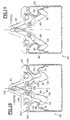
- la figure 3 est une vue en bout, partiellement en section transversale, sur laquelle la partie inférieure d'un pied est illustrée en association avec une glissière, l'ensemble étant représenté lors d'une phase d'engagement du pied dans la glissière ;
- la figure 4 est une vue similaire à celle de la figure 3 dans laquelle le pied est illustré en position de réglage ;
- la figure 5 est une vue similaire à celle de la figure 4 dans laquelle le pied est illustré en position de verrouillage ;
- la figure 6 est une vue similaire à celle de la figure 3 dans laquelle le pied est illustré au cours de sa phase de dégagement hors de la glissière ;
- la figure 7 est une vue latérale du pied dans la glissière ;
- la figure 8 est une vue similaire à celles des figures 3 à 6 qui illustre un deuxième mode de réalisation d'un agencement conforme aux enseignements de l'invention sur laquelle le pied est illustré dans une première partie de sa phase d'engagement dans la glissière ;
- la figure 9 est une vue similaire à celle de la figure 8 dans laquelle le pied est illustré dans une deuxième partie de sa phase d'engagement dans la glissière ;
- la figure 10 est une vue similaire à celle de la figure 9 dans laquelle le pied est illustré en position de réglage ;
- la figure 11 est une vue similaire à celle de la figure 10 dans laquelle le pied est illustré en position bloquée longitudinalement par rapport à la glissière ;
- la figure 12 est une vue similaire à celle de la figure 11 dans laquelle le pied est illustré en position bloquée et verrouillée longitudinalement ; et
- la figure 13 est une vue similaire à celle de la figure 12 dans laquelle le pied est illustré au cours de sa phase de dégagement hors de la glissière.
Claims (10)
- Agencement pour le réglage de la position longitudinale, et le blocage en position réglée, d'un sous-ensemble (20) notamment d'un siège, sur le plancher horizontal de l'habitacle d'un véhicule automobile équipé de deux glissières (26) parallèles qui reçoivent en coulissement longitudinal des organes de guidage des déplacements longitudinaux et de verrouillage en position réglée de pieds (24) du sous-ensemble d'orientation sensiblement verticale, caractérisé en ce que l'extrémité inférieure (44) de l'un au moins des pieds est équipée d'un mécanisme (42) expansible mobile commandé entre :en passant par au moins une position intermédiaire, dite de réglage, dans laquelle les deux organes de verrouillage (46) s'étendent chacun transversalement vers l'extérieur en regard de ladite portion interne (36) de l'un des bords supérieurs de la fente, pour retenir verticalement le pied par rapport à la glissière et permettre des déplacements longitudinaux du pied par rapport à la glissière.une première position, dite d'engagement ou de dégagement, dans laquelle deux organes de verrouillage (46) du mécanisme (42), à action symétrique et opposée par rapport à un plan longitudinal médian (P), sont dans une position escamotée vers l'intérieur dans laquelle leur encombrement transversal (L2) permet l'introduction, ou l'extraction, verticale du mécanisme dans la glissière (26) à travers une fente longitudinale médiane (38) de cette dernière délimitée par deux bords supérieurs (32) longitudinaux et parallèles de la glissière ;et une seconde position extrême, dite de verrouillage, (46, 58, 60) dans laquelle les deux organes de verrouillage s'étendent chacun transversalement vers l'extérieur en regard d'une portion interne (36, 37, 40) de l'un des bords supérieurs (32) de la fente avec laquelle ils coopèrent par accrochage, pour immobiliser verticalement et longitudinalement le pied par rapport à la glissière ;
- Agencement selon la revendication précédente, caractérisé en ce que les deux organes de verrouillage sont deux leviers de verrouillage (46) dont chacun est monté pivotant, au voisinage de son extrémité supérieure (48), autour d'un axe longitudinal (A1) d'articulation porté par le pied et dont la partie inférieure active (56) est de profil (58, 60) complémentaire du profil (37, 40) de la portion interne (36) en vis-à-vis d'un bord de la fente de la glissière.
- Agencement selon la revendication 2, caractérisé en ce que la face supérieure (58, 60) de l'extrémité inférieure (56) de chaque levier est conformée en un crochet qui coopère avec la face inférieure d'accrochage (37) de ladite portion interne (36).
- Agencement selon la revendication 3, caractérisé en ce que la face inférieure (37) d'accrochage de ladite portion interne (36) comporte une série d'encoches (40) réparties longitudinalement dont chacune constitue un cran de verrouillage susceptible de recevoir l'extrémité inférieure en crochet (58, 60) d'un levier de verrouillage (46).
- Agencement selon l'une quelconque des revendications 3 à 5, caractérisé en ce que les leviers de verrouillage (46) sont rappelés élastiquement (49) vers leur position extrême de verrouillage.
- Agencement selon la revendication 5, caractérisé en ce que la face inférieure (57) de l'extrémité inférieure (56) de chaque levier (46) est profilée de manière à coopérer avec la face supérieure de guidage (33) de ladite portion interne pour escamoter le levier (46) transversalement vers l'intérieur, à l'encontre de ses moyens élastiques (49) de rappel, lors de l'engagement du mécanisme (42) dans la glissière (26).
- Agencement selon l'une des revendications 5 ou 6, caractérisé en ce que le mécanisme (42) comporte une fourche (68) de commande des leviers (46) qui est montée mobile en coulissement vertical par rapport aux axes (A1) d'articulation des leviers (46) et dont les deux branches (70) coopèrent chacune par un profil de came (66) avec un pion (62) de commande porté par chaque levier (46) au voisinage de son extrémité inférieure (56), et dont les déplacements, à partir d'une position haute vers une position basse de déverrouillage, provoquent l'escamotage des leviers transversalement vers l'intérieur, à l'encontre de leurs moyens élastiques de rappel.
- Agencement selon la revendication 7, caractérisé en ce que les leviers (46) et la fourche de commande (68) sont montés mobiles par rapport à un support (54) qui est monté coulissant verticalement sur la partie inférieure (44) du pied (24) entre une position basse et une position haute active de verrouillage, et en ce que la partie inférieure (54) du pied prend appui verticalement sur le fond (30) de la glissière par l'intermédiaire de moyens (82) de guidage de déplacements longitudinaux du pied (24) par rapport à la glissière (26).
- Agencement selon l'une des revendications 5 ou 6, caractérisé en ce que la partie supérieure de chaque levier (46) comporte une lumière (122) en arc de cercle centrée sur son axe (A1) d'articulation dans laquelle est reçu un doigt (120) de commande porté par l'extrémité inférieure (118) d'une tige de commande (106) dont l'extrémité supérieure (108) est montée articulée, autour d'un axe longitudinal (A3), sur un coulisseau (110) de commande qui est mobile verticalement par rapport à la partie inférieure (44) du pied.
- Agencement selon l'une quelconque des revendications précédentes, caractérisé en ce que le sous-ensemble (20) est un siège de véhicule automobile.
Applications Claiming Priority (3)
| Application Number | Priority Date | Filing Date | Title |
|---|---|---|---|
| FR9705345 | 1997-04-30 | ||
| FR9705345A FR2762812B3 (fr) | 1997-04-30 | 1997-04-30 | Agencement pour le reglage de la position longitudinale et le blocage en position reglee d'un siege de vehicule automobile |
| PCT/FR1998/000819 WO1998049026A1 (fr) | 1997-04-30 | 1998-04-24 | Agencement pour le reglage de la position longitudinale et le blocage en position reglee d'un siege de vehicule automobile |
Publications (3)
| Publication Number | Publication Date |
|---|---|
| EP0979177A1 EP0979177A1 (fr) | 2000-02-16 |
| EP0979177B1 true EP0979177B1 (fr) | 2001-10-24 |
| EP0979177B2 EP0979177B2 (fr) | 2005-05-18 |
Family
ID=9506462
Family Applications (1)
| Application Number | Title | Priority Date | Filing Date |
|---|---|---|---|
| EP98922857A Expired - Lifetime EP0979177B2 (fr) | 1997-04-30 | 1998-04-24 | Agencement pour le reglage de la position longitudinale et le blocage en position reglee d'un siege de vehicule automobile |
Country Status (6)
| Country | Link |
|---|---|
| US (1) | US6299120B1 (fr) |
| EP (1) | EP0979177B2 (fr) |
| DE (1) | DE69802181T3 (fr) |
| ES (1) | ES2162448T5 (fr) |
| FR (1) | FR2762812B3 (fr) |
| WO (1) | WO1998049026A1 (fr) |
Families Citing this family (16)
| Publication number | Priority date | Publication date | Assignee | Title |
|---|---|---|---|---|
| DE10034019B4 (de) * | 2000-07-07 | 2009-01-22 | Volkswagen Ag | Befestigungsvorrichtung, insbesondere für einen Fahrzeugsitz |
| US6409063B1 (en) * | 2000-10-20 | 2002-06-25 | Jac Products, Inc. | Vehicle article carrier having angled tap plate and cooperating slat |
| FR2835790B1 (fr) * | 2002-02-08 | 2004-05-07 | Antolin Grupo Ing Sa | Dispositif de calage vertical et automatique d'un siege de vehicule |
| GB2459660B (en) * | 2008-04-29 | 2012-07-18 | Rescroft Ltd | Apparatus for connecting a seat support to a structure |
| FR2948632B1 (fr) * | 2009-07-28 | 2011-08-26 | Attax | Systeme d'accrochage d'un siege d'aeronef |
| US8894031B2 (en) | 2011-03-17 | 2014-11-25 | Honda Motor Co., Ltd. | Seating system for a motor vehicle |
| FR2986751B1 (fr) * | 2012-02-10 | 2014-03-21 | Antolin Grupo Ing Sa | Mecanisme d'ancrage d'un siege amovible |
| DE102012006687B4 (de) * | 2012-03-31 | 2022-12-29 | Adient Us Llc | Fahrzeugsitz |
| GB2501912A (en) * | 2012-05-10 | 2013-11-13 | Koller Engineering Ltd | Vehicle seat anchorage assembly |
| JP5881544B2 (ja) * | 2012-06-29 | 2016-03-09 | 株式会社ニフコ | 固定構造 |
| DE102012218762A1 (de) * | 2012-09-06 | 2014-03-06 | Burg Silvergreen Gmbh | Vorrichtung zur sicherung von ladegut |
| EP3765329A1 (fr) * | 2018-03-13 | 2021-01-20 | Pressan Madeni Esya Sanayi Ve Ticaret Anonim Sirketi | Agencement de montage de siège de véhicule |
| CN109027556B (zh) * | 2018-08-30 | 2024-04-05 | 昆山泓杰电子股份有限公司 | 升降控制机构 |
| US10648613B1 (en) * | 2018-11-19 | 2020-05-12 | Brunswick Corporation | Methods and devices for securing devices and accessories to a track system |
| FR3096745B1 (fr) * | 2019-05-28 | 2021-06-11 | Conseil & Technique | Dispositif de fixation d’un objet sur un rail avec un pas de positionnement déterminé |
| US11999271B2 (en) * | 2021-01-19 | 2024-06-04 | Textron Innovations Inc. | Seat latching mechanism |
Family Cites Families (8)
| Publication number | Priority date | Publication date | Assignee | Title |
|---|---|---|---|---|
| US3507472A (en) * | 1967-05-16 | 1970-04-21 | Howell Ind Inc | Seat mounting with telescopically arranged slide means |
| US4273487A (en) † | 1979-06-13 | 1981-06-16 | Satron, Inc. | Cargo tie-down anchor |
| EP0094438B1 (fr) * | 1982-05-13 | 1985-12-18 | Keiper Automobiltechnik GmbH. & Co. KG | Mécanisme de verrouillage pour le dispositif de déplacement longitudinal d'un siège de véhicule |
| JPH0639231B2 (ja) * | 1990-02-09 | 1994-05-25 | 株式会社大井製作所 | 車両用折畳み式シートの安全装置 |
| US5236153A (en) † | 1992-06-25 | 1993-08-17 | Laconte Richard J | Longitudinal floating pivot track fitting |
| FR2702717B1 (fr) | 1993-03-19 | 1995-05-24 | Matra Automobile | Dispositif de réglage de position de siège pour véhicule automobile et siège utilisable avec un tel dispositif. |
| DE4321720C2 (de) * | 1993-06-30 | 2001-08-16 | Keiper Gmbh & Co | Verriegelungssystem |
| AUPN395195A0 (en) * | 1995-07-04 | 1995-07-27 | Commonwealth Scientific And Industrial Research Organisation | Adjustable seat mounting mechanism |
-
1997
- 1997-04-30 FR FR9705345A patent/FR2762812B3/fr not_active Expired - Lifetime
-
1998
- 1998-04-24 ES ES98922857T patent/ES2162448T5/es not_active Expired - Lifetime
- 1998-04-24 EP EP98922857A patent/EP0979177B2/fr not_active Expired - Lifetime
- 1998-04-24 WO PCT/FR1998/000819 patent/WO1998049026A1/fr not_active Ceased
- 1998-04-24 US US09/403,764 patent/US6299120B1/en not_active Expired - Lifetime
- 1998-04-24 DE DE69802181T patent/DE69802181T3/de not_active Expired - Lifetime
Also Published As
| Publication number | Publication date |
|---|---|
| FR2762812B3 (fr) | 1999-06-04 |
| DE69802181D1 (de) | 2001-11-29 |
| EP0979177A1 (fr) | 2000-02-16 |
| ES2162448T3 (es) | 2001-12-16 |
| WO1998049026A1 (fr) | 1998-11-05 |
| DE69802181T3 (de) | 2006-03-02 |
| ES2162448T5 (es) | 2005-09-16 |
| EP0979177B2 (fr) | 2005-05-18 |
| US6299120B1 (en) | 2001-10-09 |
| DE69802181T2 (de) | 2002-05-16 |
| FR2762812A1 (fr) | 1998-11-06 |
Similar Documents
| Publication | Publication Date | Title |
|---|---|---|
| FR2762811A1 (fr) | Systeme pour le reglage de la position longitudinale et le blocage en position reglee d'un siege de vehicule automobile | |
| EP0979177B2 (fr) | Agencement pour le reglage de la position longitudinale et le blocage en position reglee d'un siege de vehicule automobile | |
| FR2762814A1 (fr) | Systeme pour le reglage de la position longitudinale et la fixation d'un siege de vehicule automobile | |
| EP0931689B1 (fr) | Siège pour véhicule, amovible, retournable et réglable longitudinalement | |
| EP0798154B1 (fr) | Glissière pour siège de véhicule, et siège comportant une telle glissière | |
| EP0925996B1 (fr) | Ensemble d'assise pour véhicule comportant un siège amovible monté sur glissières | |
| EP1699661B1 (fr) | Agencement pour le montage d un siege sur le plancher d'un vehicule au moyen de plots de guidage escamotables | |
| EP2028039B1 (fr) | Siège escamotable notamment pour véhicule automobile | |
| EP0947380B1 (fr) | Dispositif de crémaillère rapportée en fond de glissière | |
| FR2851211A1 (fr) | Siege rabattable et vehicule comportant un tel siege | |
| WO1994016928A1 (fr) | Ensemble pliable pour le support ou le transport d'une personne | |
| FR2766139A1 (fr) | Dispositif d'articulation pour siege de vehicule, et siege de vehicule comportant un tel dispositif | |
| EP0976605A1 (fr) | Siège pour véhicule, amovible, retournable et réglable longitudinalement par commandes sur ses glissières | |
| FR2762815A1 (fr) | Agencement pour le reglage de la position longitudinale et la fixation d'un siege de vehicule automobile | |
| EP1100693B1 (fr) | Agencement pour le reglage en position longitudinale et la fixation d'un element d'amenagement interieur de vehicule automobile | |
| EP0272192B1 (fr) | Bras unitaire porteur pour le soutien d'un véhicule par ses roues | |
| EP0404628B1 (fr) | Siège à dossier réglable et rabattable | |
| FR2920012A1 (fr) | Siege reglable et escamotable dans deux positions ainsi que son procede d'escamotage | |
| FR2762813A1 (fr) | Systeme pour la fixation automatique par accrochage d'un siege de vehicule automobile | |
| FR2900879A1 (fr) | Siege escamotable notamment de rang 2 | |
| EP1767395B1 (fr) | Siège pliable pour coffre de véhicule automobile | |
| FR2706409A1 (fr) | Dispositif d'accrochage réversible d'un siège sur un plancher de véhicule automobile. | |
| FR2902724A1 (fr) | Agencement d'une tablette dans un caisson, notamment pour un vehicule automobile | |
| FR3117423A3 (fr) | Structure de siege de vehicule de loisirs a armature de dossier rabattable | |
| EP4011689A1 (fr) | Structure perfectionnee de siege de vehicule de loisirs a armature de dossier rabattable |
Legal Events
| Date | Code | Title | Description |
|---|---|---|---|
| PUAI | Public reference made under article 153(3) epc to a published international application that has entered the european phase |
Free format text: ORIGINAL CODE: 0009012 |
|
| 17P | Request for examination filed |
Effective date: 19991027 |
|
| AK | Designated contracting states |
Kind code of ref document: A1 Designated state(s): DE ES FR GB IT |
|
| 17Q | First examination report despatched |
Effective date: 20000605 |
|
| GRAG | Despatch of communication of intention to grant |
Free format text: ORIGINAL CODE: EPIDOS AGRA |
|
| GRAG | Despatch of communication of intention to grant |
Free format text: ORIGINAL CODE: EPIDOS AGRA |
|
| GRAH | Despatch of communication of intention to grant a patent |
Free format text: ORIGINAL CODE: EPIDOS IGRA |
|
| GRAH | Despatch of communication of intention to grant a patent |
Free format text: ORIGINAL CODE: EPIDOS IGRA |
|
| GRAA | (expected) grant |
Free format text: ORIGINAL CODE: 0009210 |
|
| AK | Designated contracting states |
Kind code of ref document: B1 Designated state(s): DE ES FR GB IT |
|
| PG25 | Lapsed in a contracting state [announced via postgrant information from national office to epo] |
Ref country code: IT Free format text: LAPSE BECAUSE OF FAILURE TO SUBMIT A TRANSLATION OF THE DESCRIPTION OR TO PAY THE FEE WITHIN THE PRESCRIBED TIME-LIMIT;WARNING: LAPSES OF ITALIAN PATENTS WITH EFFECTIVE DATE BEFORE 2007 MAY HAVE OCCURRED AT ANY TIME BEFORE 2007. THE CORRECT EFFECTIVE DATE MAY BE DIFFERENT FROM THE ONE RECORDED. Effective date: 20011024 Ref country code: GB Free format text: LAPSE BECAUSE OF FAILURE TO SUBMIT A TRANSLATION OF THE DESCRIPTION OR TO PAY THE FEE WITHIN THE PRESCRIBED TIME-LIMIT Effective date: 20011024 |
|
| REF | Corresponds to: |
Ref document number: 69802181 Country of ref document: DE Date of ref document: 20011129 |
|
| REG | Reference to a national code |
Ref country code: ES Ref legal event code: FG2A Ref document number: 2162448 Country of ref document: ES Kind code of ref document: T3 |
|
| GBV | Gb: ep patent (uk) treated as always having been void in accordance with gb section 77(7)/1977 [no translation filed] |
Effective date: 20011024 |
|
| PLBI | Opposition filed |
Free format text: ORIGINAL CODE: 0009260 |
|
| PLBQ | Unpublished change to opponent data |
Free format text: ORIGINAL CODE: EPIDOS OPPO |
|
| RAP2 | Party data changed (patent owner data changed or rights of a patent transferred) |
Owner name: RENAULT S.A.S. |
|
| PLBF | Reply of patent proprietor to notice(s) of opposition |
Free format text: ORIGINAL CODE: EPIDOS OBSO |
|
| 26 | Opposition filed |
Opponent name: FAURECIA SIEGES D'AUTOMOBILE S.A. Effective date: 20020722 |
|
| PLBF | Reply of patent proprietor to notice(s) of opposition |
Free format text: ORIGINAL CODE: EPIDOS OBSO |
|
| PLBF | Reply of patent proprietor to notice(s) of opposition |
Free format text: ORIGINAL CODE: EPIDOS OBSO |
|
| PUAH | Patent maintained in amended form |
Free format text: ORIGINAL CODE: 0009272 |
|
| STAA | Information on the status of an ep patent application or granted ep patent |
Free format text: STATUS: PATENT MAINTAINED AS AMENDED |
|
| 27A | Patent maintained in amended form |
Effective date: 20050518 |
|
| AK | Designated contracting states |
Kind code of ref document: B2 Designated state(s): DE ES FR GB IT |
|
| REG | Reference to a national code |
Ref country code: ES Ref legal event code: DC2A Date of ref document: 20050526 Kind code of ref document: T5 |
|
| REG | Reference to a national code |
Ref country code: FR Ref legal event code: PLFP Year of fee payment: 18 |
|
| REG | Reference to a national code |
Ref country code: FR Ref legal event code: PLFP Year of fee payment: 19 |
|
| PGFP | Annual fee paid to national office [announced via postgrant information from national office to epo] |
Ref country code: ES Payment date: 20160413 Year of fee payment: 19 Ref country code: DE Payment date: 20160421 Year of fee payment: 19 |
|
| PGFP | Annual fee paid to national office [announced via postgrant information from national office to epo] |
Ref country code: FR Payment date: 20160421 Year of fee payment: 19 |
|
| REG | Reference to a national code |
Ref country code: DE Ref legal event code: R119 Ref document number: 69802181 Country of ref document: DE |
|
| REG | Reference to a national code |
Ref country code: FR Ref legal event code: ST Effective date: 20171229 |
|
| PG25 | Lapsed in a contracting state [announced via postgrant information from national office to epo] |
Ref country code: DE Free format text: LAPSE BECAUSE OF NON-PAYMENT OF DUE FEES Effective date: 20171103 Ref country code: FR Free format text: LAPSE BECAUSE OF NON-PAYMENT OF DUE FEES Effective date: 20170502 |
|
| REG | Reference to a national code |
Ref country code: ES Ref legal event code: FD2A Effective date: 20180510 |
|
| PG25 | Lapsed in a contracting state [announced via postgrant information from national office to epo] |
Ref country code: ES Free format text: LAPSE BECAUSE OF NON-PAYMENT OF DUE FEES Effective date: 20170425 |