EP0976605A1 - Siège pour véhicule, amovible, retournable et réglable longitudinalement par commandes sur ses glissières - Google Patents
Siège pour véhicule, amovible, retournable et réglable longitudinalement par commandes sur ses glissières Download PDFInfo
- Publication number
- EP0976605A1 EP0976605A1 EP99420176A EP99420176A EP0976605A1 EP 0976605 A1 EP0976605 A1 EP 0976605A1 EP 99420176 A EP99420176 A EP 99420176A EP 99420176 A EP99420176 A EP 99420176A EP 0976605 A1 EP0976605 A1 EP 0976605A1
- Authority
- EP
- European Patent Office
- Prior art keywords
- lever
- slide
- seat
- slides
- finger
- Prior art date
- Legal status (The legal status is an assumption and is not a legal conclusion. Google has not performed a legal analysis and makes no representation as to the accuracy of the status listed.)
- Granted
Links
Images


Classifications
-
- B—PERFORMING OPERATIONS; TRANSPORTING
- B60—VEHICLES IN GENERAL
- B60N—SEATS SPECIALLY ADAPTED FOR VEHICLES; VEHICLE PASSENGER ACCOMMODATION NOT OTHERWISE PROVIDED FOR
- B60N2/00—Seats specially adapted for vehicles; Arrangement or mounting of seats in vehicles
- B60N2/02—Seats specially adapted for vehicles; Arrangement or mounting of seats in vehicles the seat or part thereof being movable, e.g. adjustable
- B60N2/04—Seats specially adapted for vehicles; Arrangement or mounting of seats in vehicles the seat or part thereof being movable, e.g. adjustable the whole seat being movable
- B60N2/06—Seats specially adapted for vehicles; Arrangement or mounting of seats in vehicles the seat or part thereof being movable, e.g. adjustable the whole seat being movable slidable
- B60N2/07—Slide construction
- B60N2/0722—Constructive details
- B60N2/0732—Attachment of seat frame to the slide, e.g. eyelets
-
- B—PERFORMING OPERATIONS; TRANSPORTING
- B60—VEHICLES IN GENERAL
- B60N—SEATS SPECIALLY ADAPTED FOR VEHICLES; VEHICLE PASSENGER ACCOMMODATION NOT OTHERWISE PROVIDED FOR
- B60N2/00—Seats specially adapted for vehicles; Arrangement or mounting of seats in vehicles
- B60N2/005—Arrangement or mounting of seats in vehicles, e.g. dismountable auxiliary seats
- B60N2/015—Attaching seats directly to vehicle chassis
- B60N2/01508—Attaching seats directly to vehicle chassis using quick release attachments
-
- B—PERFORMING OPERATIONS; TRANSPORTING
- B60—VEHICLES IN GENERAL
- B60N—SEATS SPECIALLY ADAPTED FOR VEHICLES; VEHICLE PASSENGER ACCOMMODATION NOT OTHERWISE PROVIDED FOR
- B60N2/00—Seats specially adapted for vehicles; Arrangement or mounting of seats in vehicles
- B60N2/02—Seats specially adapted for vehicles; Arrangement or mounting of seats in vehicles the seat or part thereof being movable, e.g. adjustable
- B60N2/04—Seats specially adapted for vehicles; Arrangement or mounting of seats in vehicles the seat or part thereof being movable, e.g. adjustable the whole seat being movable
- B60N2/06—Seats specially adapted for vehicles; Arrangement or mounting of seats in vehicles the seat or part thereof being movable, e.g. adjustable the whole seat being movable slidable
- B60N2/07—Slide construction
- B60N2/0702—Slide construction characterised by its cross-section
- B60N2/0715—C or U-shaped
-
- B—PERFORMING OPERATIONS; TRANSPORTING
- B60—VEHICLES IN GENERAL
- B60N—SEATS SPECIALLY ADAPTED FOR VEHICLES; VEHICLE PASSENGER ACCOMMODATION NOT OTHERWISE PROVIDED FOR
- B60N2/00—Seats specially adapted for vehicles; Arrangement or mounting of seats in vehicles
- B60N2/02—Seats specially adapted for vehicles; Arrangement or mounting of seats in vehicles the seat or part thereof being movable, e.g. adjustable
- B60N2/04—Seats specially adapted for vehicles; Arrangement or mounting of seats in vehicles the seat or part thereof being movable, e.g. adjustable the whole seat being movable
- B60N2/06—Seats specially adapted for vehicles; Arrangement or mounting of seats in vehicles the seat or part thereof being movable, e.g. adjustable the whole seat being movable slidable
- B60N2/08—Seats specially adapted for vehicles; Arrangement or mounting of seats in vehicles the seat or part thereof being movable, e.g. adjustable the whole seat being movable slidable characterised by the locking device
- B60N2/0812—Location of the latch
- B60N2/0818—Location of the latch inside the rail
-
- B—PERFORMING OPERATIONS; TRANSPORTING
- B60—VEHICLES IN GENERAL
- B60N—SEATS SPECIALLY ADAPTED FOR VEHICLES; VEHICLE PASSENGER ACCOMMODATION NOT OTHERWISE PROVIDED FOR
- B60N2/00—Seats specially adapted for vehicles; Arrangement or mounting of seats in vehicles
- B60N2/02—Seats specially adapted for vehicles; Arrangement or mounting of seats in vehicles the seat or part thereof being movable, e.g. adjustable
- B60N2/04—Seats specially adapted for vehicles; Arrangement or mounting of seats in vehicles the seat or part thereof being movable, e.g. adjustable the whole seat being movable
- B60N2/06—Seats specially adapted for vehicles; Arrangement or mounting of seats in vehicles the seat or part thereof being movable, e.g. adjustable the whole seat being movable slidable
- B60N2/08—Seats specially adapted for vehicles; Arrangement or mounting of seats in vehicles the seat or part thereof being movable, e.g. adjustable the whole seat being movable slidable characterised by the locking device
- B60N2/0831—Movement of the latch
- B60N2/0837—Movement of the latch pivoting
- B60N2/085—Movement of the latch pivoting about a transversal axis
Definitions
- the invention relates to a vehicle seat, removable, reversible and longitudinally adjustable with respect to two slides fixed to the floor of the vehicle.
- This type of seat is, for example, used in vehicles whose the cabin can be transformed to suit the number of people transport, by changing the number of seats and / or the interval between seats, or to increase the area reserved for baggage or cargo by removing some seats. This is the case, for example, in so-called vehicles minivan, where some seats can be returned.
- French patent application 2,700,735 describes a seat of this type. type in which the foot unlocking control means and the slider release control means are arranged under the seat.
- This arrangement which brings together on the seat all the means of control of its functionality, has the disadvantage of weighing down this seat and to increase the cost, but also to facilitate, for an inattentive passenger, confusion between the longitudinal adjustment control and the control locking of the feet, with the risk of detaching the seat from its slides at a time when the vehicle is braking.
- the object of the present invention is to remedy these drawbacks by providing a seat in which the unlocking control slides are on the slides.
- the passenger always has, near one of the front feet of the seat, an unlocking lever placed outside the seat and of which the actuation leads, by the reference carried by the seat, the operation of means for unlocking the two slides.
- the invention also provides means allowing, when the slides are not used, to eclipse the levers to prevent them form protrusions which can be hung and deteriorated or which can the loading of the floor freed from the seats, and, when a seat is set up, to bring the only useful lever in the position of use.
- each joystick control is mounted to rotate freely on a transverse axis of the slide, is permanently subjected to the action of a torsion spring tending to fold against the central part of the slide and in the slide, and is linked in rotation, with the possibility of relative angular displacement over the travel of release command, to a notched disc, the notch of which is suitable, at the end of manual straightening of the lever, to cooperate with a locking finger, said finger being connected to means capable of eclipsing it when the seat outside the slide.
- each control lever is mounted free in rotation on a transverse axis of the slide and is permanently subjected to the action of a torsion spring, tending to fold it down on the end of the slide and in the slide, while the front foot of the seat coming in the anchoring zone juxtaposed with the lever has a lateral spur adapted, at the end of engagement, to come to bear on the active end the joystick to bring this joystick into the use position, with its free end protruding above the slide.
- the lever is straightened during installation of the seat, by the seat itself, and its drawdown is also automatic.
- the reference numeral 2 denotes, so general, a seat with a seat fitted with two 3d, 3g front legs and two rear legs 4d and 4g. Each foot is associated with locks capable of cooperate with anchoring means carried by a movable slide 5. in a slide 6.
- each foot has two latches 7 and 8, articulated by transverse axes 9 and 10 on the corresponding foot and recalled to the locked position by springs 12 and 13, visible in Figure 1.
- these locks 7 and 8 are provided at their free end with hooks 7a, 8a, arranged back to back and able to hang under the edge of an opening 14 formed in a plate 15 carried by a slide 5.
- the latches 7 of the two feet rear, as well as the locks 7 of the two front feet, are connected by a opening control rod, respectively 16 and 17 ( Figure 1).
- each slide 6 is constituted by a metal profile, for example aluminum, having, in cross section, the general shape of a U and comprising a core 18, flat and horizontal, capable of coming to bear on the floor of a vehicle and receive on its internal face a steel plate 19 whose two wings 19a are shaped like a rack.
- the connection of the slide with the floor is provided by screws 20 passing through its core 18 and the profile 19, as shown FIG. 5.
- the two wings 22 of the slide comprise a straight part 22a, and a rounded upper part 22b and forming an internal groove 23 of section transverse in V with curvilinear bottom. Part 22b is extended by a return 22c, facing inward.
- the slide 5 is composed of two longitudinal cheeks 25 which are connected to each other by means of the plates 15 and connecting pieces 26. More specifically, each plate 15 and parts 26 have studs 27 which, after having passed through cutouts 28 formed in the corresponding cheeks, are riveted against these cheeks. Each plate 15 has, in its central part and on each side, a lateral pin 29 which, after having passed through a cutout 30 in the plate, receives a shoe 32. As shown in FIG. 5, each shoe of cross section semi circular is able to slide in the groove 23 of the slide. This same figure shows that the connecting piece 26 is supported by two tenons side 33 under steps 34 of the profile constituting the slide 6 for ensure the setting in vertical translation of the slide with respect to this slide.
- the slide 5 carries locking means relative to the slide, means which in the embodiment shown, consist by two levers 35 arranged outside the cheeks 25 of the slide and each articulated on a transverse pin 36, carried by the corresponding cheek.
- Each lever 35 is provided at one of its ends with notches 37 able to cooperate with the corresponding rack 19a. At its other end 35a, each lever 35 is subjected to the action of a return spring 38 tending to engage its notches in the rack.
- the means for unlocking these levers comprise means arranged in the slide, return means between the two slides and manual control means carried by each of the sliders.
- the control means carried by each slide consist of a rocker 40 disposed between the foot anchoring zones and carrying, at substantially mid-length, an axis transverse 42 mounted sliding vertically in oblong openings vertical 43 of the cheeks 25.
- the ends of the axis 42 extend beyond cheeks 25 for entering bores 44 formed at the ends non-notched levers 35.
- the flip-flop 40 includes means limiting its vertical movements and, for example, lugs 45 projecting laterally outwards and sliding vertically in notches 46 formed in the cheeks and opening down.
- Each of the flip-flops 40 of the slides of the two slides associated with the same seat is controlled simultaneously with the other rocks thanks to a reference 48 arranged transversely under the seat.
- the reference consists by a tubular pin 49 mounted to rotate freely under the seat and one of the ends, for example its left end is provided with a bent lever 50, while the other end is integral with a control finger 52.
- the lever bent 50 has a branch 50a, corresponding to finger 52 and suitable for come to bear on the corresponding end of the underlying lever 40, and a branch 50b able to cooperate with a manual control lever 53.
- Tension springs 54 (FIG. 1), interposed between the seat frame, and respectively the finger 50a and the finger 54, communicate permanently at reference 48 a return torque bringing branch 50b of the bent lever against the lever 53.
- the lever 53 of each slide is mounted to rotate freely on an axis 55.
- slide 5 running in the slide which is on the left, in relation to a seat turned facing on the road, this axis is on the front end of the slide. while what on the slide running in the right slide, this axis is at the rear end of the slide.
- the handle 53 is associated with a torsion spring 56 which la permanently requests in the direction of arrow 57, that is to say which tends to fold down on the slide, and so that its grip 53a either substantially in the central part of this slide where it fits in a recess 58 of the rocker.
- the lever is linked in rotation to a disc 59 comprising a notch 60.
- the disc 59 is mounted to rotate freely on the axis 55 of the lever 53 but is linked in rotation to it with the possibility of relative angular displacement limited by a protruding transverse pin 62 laterally from the joystick and entering an oblong circular lumen 63 provided in this disc.
- the means for locking the lever in the use position include a bent lever 64 and a control plate 65 arranged between the articulation of the control handle and the anchoring area of the foot corresponding, i.e. plate 15.
- the lever 64 which is articulated near its elbow on an axis 66, comprises, at the end of its substantially horizontal branch 64a, a finger lock 67 projecting upwards and capable of penetrating into the notch 60 of the disc 59, under the action of a torsion spring 68.
- the horizontal branch 64a also carries a transverse lug 69 projecting in the direction of the control plate 65.
- This plate command is crossed by a recess 70 surrounding the axis 66 and by a recess 72 surrounding the above-mentioned tenon 69. Thanks to this, the plate presents a possibility of limited relative movement relative to lever 64, both in rotation only in transverse translation.
- a tension spring 73 is interposed between the plate 65 and the substantially vertical branch of the lever 64.
- this plate includes a detector finger 65a which extends below the anchor plate 15 and so that, in the absence of a seat leg, its end, provided with bevels 74 on its edges, respectively upper and lower, either below the opening 14 of the plate 15 and in the path of engagement of the foot of the corresponding seat.
- one of the seat legs and in this case the left front leg 3g has a groove 76, visible in FIGS. 12 to 16, able to cooperate with the detector finger 65a.
- the lever 53 is supported by a protuberance 53b on the anchoring plate 15 and protrudes upwards, while by being on the side of the opening 14, formed in this plate.
- the edge lower of the front left foot 3g meets the end of the detector finger 65a and makes this finger move back in the direction of arrow 80 in FIG. 12.
- the groove 76 of the foot 3g comes at the end of the detector finger 65a, it penetrates into this groove under the action of the spring 73 and remains in this position as long as the seat is on the slides.
- the joystick 53 which controls the longitudinal movement, cannot be combined with the lever 17 for unlocking the front feet.
- the seat is free of any control mechanism release of the slides and any control handle that can be deteriorated by handling of the seat, outside the vehicle.
- the clearance of the front left foot 3g first causes, as shown in Figures 14 and 15, pivoting upwards (arrow 86) of the detector finger 65a. Then and as soon that the lower edge of the groove 76 formed in the front left foot 3g meets the lower bevel 74 of the finger 65a, it hunts backwards and into the direction of the arrow 85, this finger 65a and the assembly of the plate 65, as shown in Figure 15.
- the tilting of the plate 65 in the direction of arrows 86 are reflected, by its tenon 69, on the bent lever 64 including the finger 67 emerges from the notch 60 of the disc 59 linked in rotation to the lever 53. It As a result, as shown in FIG.
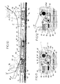
- FIG. 17 to 19 The embodiment shown in Figures 17 to 19 is differentiates from the previous one by the locking means of the feet. by the means for returning to the position of use of the control levers and by the control means of the notched levers ensuring the blocking of runners compared to runners.
- each rod 202 is constituted by a through axis the wings 204 of the U-shaped section constituting the body of the slide 105.
- This axis carries, at each of its ends, a roller 205 circulating in a groove longitudinal 206 formed in the inner part of the wings 207 of the profile constituting the slide 106.
- the anchoring well is constituted by a piece of synthetic material 208.
- FIG. 19 shows that each slide 105 carries two notched levers 135, articulated on pivots 136 and cooperating with a rack 209, produced by perforating the bottom of the profile constituting the slide 106.
- FIG. 17 which represents, in longitudinal section, the slide from the left slide, shows that the two levers 135 are oriented with their notches 137 facing backwards and their notched parts 135a coming from below the active part 153d of the control lever 153.
- This control lever is articulated on an axis 155 and is constantly recalled by a torsion spring 156, so that its handle gripping 153a is folded over the front end of the slide.
- Both notched levers 135 are connected, in their notched parts.
- an axis transverse 210 which is substantially arranged in the median plane Pm transverse of the slide 105.
- This axis is straddled by a fork 213 a complementary lever 214, articulated at 215 on the slide.
- the other end 216 of this lever 214 extends towards the anchoring zone of the rear feet, so as to form a bearing surface which is symmetrical to that formed by the notched part 135a of the levers 135 relative to the plane transverse median Pm of the slide.
- this end 216 of the complementary lever comes below the active end 153d of the control lever 153, as shown in phantom in Figure 17.
- the slide 105 circulating in the slide of left comprises, going from front to rear, axis 202 for anchoring the front leg 103g, axis 155 for the articulation of the control lever 153, the pivots 136 for the articulation of the notched levers 135, the axis 215 for the lever intermediate 214 and axis 202 for anchoring the rear leg 4g.
- the slide for the right slide has axis 202 for anchoring the foot front 3d, pivots 136, axis 215 for lever 214, axis 155 for the articulation of the lever and the axis 202 for the anchoring of the rear foot 4d.
- the seat base carries, on its front part, a reference 148 of which the left end is provided with a lever 150, capable of cooperating with the lever 153 and whose right end is provided with a finger 152 capable of cooperate with the bearing surface 135a of the notched levers of the other slide.
- the seat comprises a lateral spur 220, protruding at the rear of his front left foot and suitable, during of the engagement of the headquarters, coming to bear on the active part 153d of the control lever to rotate this lever and bring it into its position of use shown in Figure 17.
Abstract
Description
- une manette de commande manuelle articulée sur l'une des extrémités de chaque coulisseau, près de la zone d'ancrage d'un pied, cette extrémité étant différente sur les deux coulisseaux pour un même siège,
- et un renvoi transversal articulé près des pieds avant, sous l'assise du siège et dont une extrémité est apte à coopérer avec la manette de commande de déblocage de l'un des coulisseaux, tandis que l'autre extrémité de ce verrou porte un doigt apte à coopérer avec les moyens de déblocage de l'autre coulisseau dans sa glissière.
Claims (6)
- Siège pour véhicule, amovible, retournable et réglable longitudinalement, par commandes sur ses glissières, comprenant quatre pieds munis chacun de verrous (7, 8, 200, 202) à ressorts et déverrouillables par une commande manuelle, ces verrous étant aptes à coopérer avec des moyens complémentaires (15, 202) portés par des coulisseaux (5, 105) mobiles dans deux glissières parallèles (6, 106) fixées sur le plancher du véhicule, chacun de ces coulisseaux étant muni de moyens de blocage constitués par au moins un levier cranté (135) à déblocage manuel et dont les crans (137) sont engagés, par des moyens à ressorts, dans une crémaillère (19, 209) de la glissière, caractérisé en ce que les moyens de déblocage manuel de chacun des coulisseaux (5, 105) comprennent :une manette de commande manuelle (53, 153) articulée sur l'une des extrémités de chaque coulisseau (5, 105), près de la zone d'ancrage d'un pied (3g), cette extrémité étant différente sur les deux coulisseaux (5) pour un même siège,et un renvoi transversal (48, 148) articulé près des pieds avant sous l'assise du siège (2) et dont une extrémité (50, 150) aménagée pour coopérer avec la manette (53) de commande de déblocage de l'un des coulisseaux, tandis que l'autre extrémité de ce renvoi porte un doigt (52, 152) apte à coopérer avec les moyens de déblocage de l'autre coulisseau (5) dans sa glissière (6).
- Siège selon la revendication 1, caractérisé en ce que chaque manette de commande (53) est montée libre en rotation sur un axe transversal (55) du coulisseau (5), est soumise en permanence à l'action d'un ressort de torsion (56) tendant à la rabattre contre la partie centrale du coulisseau (5) et dans la glissière (6), et est liée en rotation, avec possibilité de déplacement angulaire relatif sur la course de commande de déblocage, à un disque cranté (59), dont le cran (60) est apte, en fin de redressement manuel de la manette. à coopérer avec un doigt de verrouillage (67), ledit doigt étant relié à des moyens (64, 65) aptes à l'éclipser lors du dégagement du siège.
- Siège selon la revendication 2, caractérisé en ce que le doigt de verrouillage eclipsable (67) fait saillie vers le haut de la branche sensiblement horizontale (64) d'un levier coudé (64), articulé près de son coude sur un axe transversal (66) du coulisseau (5) et rappelé par un ressort (68) en position d'engagement de son doigt dans le cran (60) du disque (59), alors que la branche verticale du levier est munie d'un moyen d'accrochage pour l'une des extrémités d'un ressort de traction (73) et que ce levier coudé est juxtaposé à une platine de commande (65) montée à coulissement limité et à pivotement limité par rapport au levier (64), ladite platine portant des moyens d'accrochage pour l'autre extrémité du ressort de traction (73) et comportant, à l'opposé de ces moyens d'accrochage, un doigt détecteur (65a) sécantant la trajectoire d'engagement du pied de siège (3g) correspondant dans les moyens d'ancrage complémentaires (15) du coulisseau, tandis que ledit pied de siège (3g) comporte une gorge (76) apte, lors de son engagement, à recevoir l'extrémité (65a) du doigt détecteur (65) poussé par son ressort et, lors de son dégagement, à coopérer avec le biseau (74) de ce doigt pour le chasser à l'encontre de son ressort et le faire pivoter en entraínant le pivotement du levier coudé (64) dans le sens du déverrouillage de la manette de commande (53).
- Siège selon la revendication 2, caractérisé en ce que le renvoi (48) porté par le siège (2) comporte, à son extrémité destinée à coopérer avec l'une des deux manettes de commande (53) des coulisseaux (5), un levier coudé dont l'une des branches (50b) reçoit l'appui de la manette (53) et dont l'autre branche (50a) coopère avec l'une des extrémités d'une bascule (40) de commande de déblocable du coulisseau (5), ladite bascule (40) étant reliée, sensiblement à mi longueur et par un axe transversal (42), à l'extrémité non crantée (35a) du levier cranté (35) de blocage du coulisseau et comportant, à chaque extrémité, des moyens (45) limitant le pivotement vers le haut de cette extrémité, lorsque l'autre extrémité est abaissée par la branche du levier coudé (50) du renvoi.
- Siège selon la revendication 1, caractérisé en ce que chaque manette de commande (153) est montée libre en rotation sur un axe transversal (155) du coulisseau (105) et est soumise en permanence à l'action d'un ressort de torsion (156), tendant à la rabattre sur l'extrémité du coulisseau (105) et dans la glissière (106), tandis que le pied avant (103g) du siège venant dans la zone d'ancrage juxtaposée à la manette (153) comporte un éperon latéral (220) apte, en fin d'engagement, à venir en appui sur l'extrémité active (153d) de la manette pour amener cette manette en position d'utilisation avec son extrémité libre en saillie au-dessus de la glissière (106).
- Siège selon la revendication 5, caractérisé en ce que le coulisseau (105) de la glissière gauche (106) comprend, en allant de l'avant vers l'arrière, l'axe d'ancrage (202) du pied avant (103g), l'articulation (155) de la manette de commande (153), l'articulation (136) du levier cranté (135). dont l'extrémité non crantée est sous l'extrémité active (153d) de ladite manette, une articulation (215) pour un levier complémentaire (214) dont une extrémité fourchue (213) enfourche un doigt transversal (210) porté par la partie crantée du levier (135), et dont l'autre extrémité (214) est près du puits d'ancrage arrière et est apte, lorsque le siège est en position retournée à recevoir l'appui d'un levier (152) solidaire du renvoi de siège, et, enfin, l'axe (202) d'ancrage du pied arrière (104g), tandis que le coulisseau (105) de la glissière de droite (106) comprend, en allant de l'avant vers l'arrière, l'axe d'ancrage (202) du pied avant (103d), l'articulation (136) du levier cranté (135) dont l'extrémité non crantée est apte, lorsque le siège est en position normale, à recevoir l'appui du levier (152) solidaire du renvoi (148) de siège, une articulation (215) pour un levier complémentaire (214) identique en forme, fonction et disposition à celui du coulisseau de gauche, mais dont l'extrémité libre (216) est au-dessous de l'extrémité active (153a) de la manette de commande (153), l'articulation (155) pour cette manette de commande et un axe d'ancrage (202) du pied arrière correspondant (104d).
Applications Claiming Priority (2)
| Application Number | Priority Date | Filing Date | Title |
|---|---|---|---|
| FR9810102A FR2781732B1 (fr) | 1998-07-31 | 1998-07-31 | Siege pour vehicule, amovible, retournable et reglable longitudinalement par commandes sur ses glissieres |
| FR9810102 | 2000-09-11 |
Publications (2)
| Publication Number | Publication Date |
|---|---|
| EP0976605A1 true EP0976605A1 (fr) | 2000-02-02 |
| EP0976605B1 EP0976605B1 (fr) | 2004-10-20 |
Family
ID=9529453
Family Applications (1)
| Application Number | Title | Priority Date | Filing Date |
|---|---|---|---|
| EP99420176A Expired - Lifetime EP0976605B1 (fr) | 1998-07-31 | 1999-07-30 | Siège pour véhicule, amovible, retournable et réglable longitudinalement par commandes sur ses glissières |
Country Status (5)
| Country | Link |
|---|---|
| US (1) | US6161892A (fr) |
| EP (1) | EP0976605B1 (fr) |
| DE (1) | DE69921244T2 (fr) |
| ES (1) | ES2229649T3 (fr) |
| FR (1) | FR2781732B1 (fr) |
Cited By (3)
| Publication number | Priority date | Publication date | Assignee | Title |
|---|---|---|---|---|
| EP1176047A1 (fr) * | 2000-07-27 | 2002-01-30 | Grupo Antolin-Ingenieria, S.A. | Dispositif de guidage et d'ancrage pour siège amovible de véhicule |
| FR2894890A1 (fr) * | 2005-12-21 | 2007-06-22 | Pellegrin Veronique Flosi | Dispositif longitudinal de reglage d'un siege automobile |
| CN107980029A (zh) * | 2015-07-31 | 2018-05-01 | 安道拓卢森堡控股有限公司 | 用于车辆座椅的纵向调节器的致动机构以及具有该制动机构的纵向调节器 |
Families Citing this family (22)
| Publication number | Priority date | Publication date | Assignee | Title |
|---|---|---|---|---|
| DE10027063C2 (de) * | 2000-05-26 | 2002-08-29 | Brose Fahrzeugteile | Sitzmodul |
| JP4465835B2 (ja) * | 2000-08-28 | 2010-05-26 | アイシン精機株式会社 | 車両用シート装置 |
| DE10139630A1 (de) * | 2001-08-11 | 2003-03-06 | Keiper Gmbh & Co | Verriegelungsvorrichtung für einen Fahrzeugsitz |
| KR100453026B1 (ko) * | 2002-07-27 | 2004-10-14 | 대원산업 주식회사 | 자동 텀블 및 대좌 조립이 가능한 착탈식 시트 |
| US6860558B1 (en) | 2003-02-05 | 2005-03-01 | Hickory Springs Manufacturing Company | Locking mechanism for glider chairs in recreational vehicles |
| US8534735B2 (en) * | 2003-06-05 | 2013-09-17 | The Riverbank, Llc | Apparatus for configuring the interior space of a vehicle |
| US20040256873A1 (en) * | 2003-06-05 | 2004-12-23 | Mcmanus Patrick W. | Apparatus for configuring the cargo area of a vehicle |
| US6761402B1 (en) * | 2003-06-12 | 2004-07-13 | Tachi-S Co., Ltd. | Structure of a vehicle seat |
| US6991285B1 (en) | 2004-03-17 | 2006-01-31 | Hemenway Michael S | Reversible seatback for a vehicle |
| US8454087B2 (en) * | 2004-05-28 | 2013-06-04 | Wms Gaming Inc. | Chair interconnection for a gaming machine |
| US8262478B2 (en) | 2004-05-28 | 2012-09-11 | Wms Gaming Inc. | Gaming device with attached audio-capable chair |
| US7293752B2 (en) * | 2004-10-28 | 2007-11-13 | Lear Corporation | Positive engagement latch for a vehicle seat |
| JP4797625B2 (ja) * | 2005-12-28 | 2011-10-19 | アイシン精機株式会社 | 車両用シートスライド装置 |
| US7581706B2 (en) * | 2006-06-26 | 2009-09-01 | Lear Corporation | Shape memory alloy (SMA) system |
| JP5225610B2 (ja) * | 2007-05-17 | 2013-07-03 | トヨタ紡織株式会社 | 車両用シート |
| US8182016B2 (en) * | 2008-01-04 | 2012-05-22 | Chrysler Group Llc | Swivel seating system |
| US7914077B2 (en) * | 2009-06-18 | 2011-03-29 | Toyota Motor Engineering & Manufacturing North America, Inc. | Single motion load bearing release handle |
| JP5327002B2 (ja) * | 2009-11-05 | 2013-10-30 | アイシン精機株式会社 | 車両用シートスライド装置 |
| US9855868B2 (en) * | 2012-06-04 | 2018-01-02 | Lear Corporation | Seat adjuster assembly |
| US10183596B2 (en) * | 2017-03-30 | 2019-01-22 | Ts Tech Co., Ltd. | Vehicle seat |
| WO2020111118A1 (fr) * | 2018-11-29 | 2020-06-04 | テイ・エス テック株式会社 | Système de siège et dispositif d'expérience de siège |
| US11332043B2 (en) * | 2020-02-25 | 2022-05-17 | Ford Global Technologies, Llc | Connector assembly for a vehicle seat |
Citations (5)
| Publication number | Priority date | Publication date | Assignee | Title |
|---|---|---|---|---|
| US4277043A (en) * | 1979-05-25 | 1981-07-07 | Koehler-Dayton, Inc. | Locking assembly for aircraft seat |
| GB2219493A (en) * | 1988-06-11 | 1989-12-13 | Unwin C N Ltds | Vehicle furniture anchorages |
| FR2700735A1 (fr) * | 1993-01-27 | 1994-07-29 | Matra Automobile | Siège de véhicule enlevable et réglable en position. |
| EP0615879A1 (fr) * | 1993-03-19 | 1994-09-21 | Matra Automobiles | Dispositif de réglage de position de siège pour véhicule automobile |
| DE19729581A1 (de) * | 1996-07-11 | 1998-01-15 | Faure Bertrand Equipements Sa | Antriebsvorrichtung zur Entriegelung eines Fahrzeugsitzes von dem Boden |
Family Cites Families (7)
| Publication number | Priority date | Publication date | Assignee | Title |
|---|---|---|---|---|
| NO932534L (no) * | 1993-07-12 | 1995-01-13 | Norsk Hydro As | Et system for låsing og tilpassing av bilseter |
| US5636884A (en) * | 1995-03-15 | 1997-06-10 | Lear Seating Corporation | Pivotal seat and support |
| US5741000A (en) * | 1995-09-13 | 1998-04-21 | Atoma International, Inc. | Vehicle seat track assembly |
| US5765803A (en) * | 1995-12-15 | 1998-06-16 | Graham; David S. | Vehicle seat suspension system |
| US5711505A (en) * | 1996-09-30 | 1998-01-27 | Tachi-S Co., Ltd. | Slide rail device for jump seat |
| US5911465A (en) * | 1997-09-08 | 1999-06-15 | Mazda Motor Corporation | Rear seat attachment apparatus for vehicle |
| FR2768378B1 (fr) * | 1997-09-12 | 1999-11-12 | Faure Bertrand Equipements Sa | Glissiere pour un siege amovible de vehicule automobile |
-
1998
- 1998-07-31 FR FR9810102A patent/FR2781732B1/fr not_active Expired - Fee Related
-
1999
- 1999-07-30 ES ES99420176T patent/ES2229649T3/es not_active Expired - Lifetime
- 1999-07-30 EP EP99420176A patent/EP0976605B1/fr not_active Expired - Lifetime
- 1999-07-30 DE DE69921244T patent/DE69921244T2/de not_active Expired - Lifetime
- 1999-08-02 US US09/365,021 patent/US6161892A/en not_active Expired - Fee Related
Patent Citations (5)
| Publication number | Priority date | Publication date | Assignee | Title |
|---|---|---|---|---|
| US4277043A (en) * | 1979-05-25 | 1981-07-07 | Koehler-Dayton, Inc. | Locking assembly for aircraft seat |
| GB2219493A (en) * | 1988-06-11 | 1989-12-13 | Unwin C N Ltds | Vehicle furniture anchorages |
| FR2700735A1 (fr) * | 1993-01-27 | 1994-07-29 | Matra Automobile | Siège de véhicule enlevable et réglable en position. |
| EP0615879A1 (fr) * | 1993-03-19 | 1994-09-21 | Matra Automobiles | Dispositif de réglage de position de siège pour véhicule automobile |
| DE19729581A1 (de) * | 1996-07-11 | 1998-01-15 | Faure Bertrand Equipements Sa | Antriebsvorrichtung zur Entriegelung eines Fahrzeugsitzes von dem Boden |
Cited By (5)
| Publication number | Priority date | Publication date | Assignee | Title |
|---|---|---|---|---|
| EP1176047A1 (fr) * | 2000-07-27 | 2002-01-30 | Grupo Antolin-Ingenieria, S.A. | Dispositif de guidage et d'ancrage pour siège amovible de véhicule |
| FR2812251A1 (fr) * | 2000-07-27 | 2002-02-01 | Antolin Grupo Ing Sa | Dispositif de guidage et d'ancrage pour siege amovible de vehicule |
| FR2894890A1 (fr) * | 2005-12-21 | 2007-06-22 | Pellegrin Veronique Flosi | Dispositif longitudinal de reglage d'un siege automobile |
| CN107980029A (zh) * | 2015-07-31 | 2018-05-01 | 安道拓卢森堡控股有限公司 | 用于车辆座椅的纵向调节器的致动机构以及具有该制动机构的纵向调节器 |
| US10500986B2 (en) | 2015-07-31 | 2019-12-10 | Adient Luxembourg Holding S.à{grave over (.)}r.l. | Actuating mechanism for a longitudinal adjuster of a vehicle seat, and longitudinal adjuster with such an actuating mechanism |
Also Published As
| Publication number | Publication date |
|---|---|
| ES2229649T3 (es) | 2005-04-16 |
| FR2781732A1 (fr) | 2000-02-04 |
| DE69921244T2 (de) | 2005-02-24 |
| EP0976605B1 (fr) | 2004-10-20 |
| US6161892A (en) | 2000-12-19 |
| FR2781732B1 (fr) | 2000-10-06 |
| DE69921244D1 (de) | 2004-11-25 |
Similar Documents
| Publication | Publication Date | Title |
|---|---|---|
| EP0976605B1 (fr) | Siège pour véhicule, amovible, retournable et réglable longitudinalement par commandes sur ses glissières | |
| EP0945301B1 (fr) | Glissière pour siège de véhicule et siège comportant une telle glissiere | |
| EP0931689B1 (fr) | Siège pour véhicule, amovible, retournable et réglable longitudinalement | |
| EP0925996B1 (fr) | Ensemble d'assise pour véhicule comportant un siège amovible monté sur glissières | |
| CA2460630C (fr) | Glissiere pour siege de vehicule automobile | |
| EP0798154B1 (fr) | Glissière pour siège de véhicule, et siège comportant une telle glissière | |
| EP0891888B1 (fr) | Dispositif de fixation et de réglage de la position longitudinale d'un siège amovible et retournable pour véhicule | |
| EP1176047B1 (fr) | Dispositif de guidage et d'ancrage pour siège amovible de véhicule | |
| EP0749864B1 (fr) | Fixation de sécurité pour siège amovible de véhicule | |
| FR2797234A1 (fr) | Glissiere pour siege de vehicule et siege comportant une telle glissiere | |
| EP0723889B1 (fr) | Glissière pour sièges de véhicules | |
| FR2851211A1 (fr) | Siege rabattable et vehicule comportant un tel siege | |
| FR2625955A1 (fr) | Siege rabattable de vehicule, notamment pour vehicules utilitaires | |
| FR2556946A1 (fr) | Siege mobile, notamment siege amovible pour vehicule | |
| FR2853865A1 (fr) | Glissiere pour siege de vehicule | |
| FR2882538A1 (fr) | Glissiere pour siege de vehicule et siege comportant une telle glissiere | |
| FR2882537A1 (fr) | Siege de vehicule muni d'un dossier rabattable se debloquant lors du retour en position de l'assise | |
| WO2006061507A1 (fr) | Dispositif de reglage longitudinal de la position d'un element, partie d'assise ou de dossier constitutif d'un siege automobile pour enfant. | |
| FR2785240A1 (fr) | Glissiere pour siege amovible de vehicule, ensemble d'assise comprenant une telle glissiere, et vehicule equipe de telles glissieres | |
| EP0734665B1 (fr) | Ensemble de literie à sommiers superposés rabattables pourvu de moyens d'appui au sol | |
| CA2274937A1 (fr) | Equipement de vehicule pour assurer le transfert et la fixation d'un siege transformable en fauteuil roulant pour handicape | |
| EP0965478A1 (fr) | Siège arrière réglable en position longitudinale dans un habitacle de véhicule automobile | |
| FR2683781A1 (fr) | Dispositif d'accrochage automatique au plancher d'un vehicule d'un moyen de fixation d'une ceinture de securite. | |
| FR2771348A1 (fr) | Ensemble d'assise pour vehicule comportant un siege amovible monte sur glissieres | |
| FR2578207A2 (fr) | Perfectionnements aux sieges de vehicule a dossier reglable en inclinaison |
Legal Events
| Date | Code | Title | Description |
|---|---|---|---|
| PUAI | Public reference made under article 153(3) epc to a published international application that has entered the european phase |
Free format text: ORIGINAL CODE: 0009012 |
|
| AK | Designated contracting states |
Kind code of ref document: A1 Designated state(s): DE ES FR GB IT PT |
|
| AX | Request for extension of the european patent |
Free format text: AL;LT;LV;MK;RO;SI |
|
| 17P | Request for examination filed |
Effective date: 20000626 |
|
| AKX | Designation fees paid |
Free format text: DE ES FR GB IT PT |
|
| GRAP | Despatch of communication of intention to grant a patent |
Free format text: ORIGINAL CODE: EPIDOSNIGR1 |
|
| RAP1 | Party data changed (applicant data changed or rights of an application transferred) |
Owner name: GRUPO ANTOLIN-INGENIERIA, S.A. |
|
| GRAS | Grant fee paid |
Free format text: ORIGINAL CODE: EPIDOSNIGR3 |
|
| GRAA | (expected) grant |
Free format text: ORIGINAL CODE: 0009210 |
|
| AK | Designated contracting states |
Kind code of ref document: B1 Designated state(s): DE ES FR GB IT PT |
|
| REG | Reference to a national code |
Ref country code: GB Ref legal event code: FG4D Free format text: NOT ENGLISH |
|
| GBT | Gb: translation of ep patent filed (gb section 77(6)(a)/1977) |
Effective date: 20041020 |
|
| REF | Corresponds to: |
Ref document number: 69921244 Country of ref document: DE Date of ref document: 20041125 Kind code of ref document: P |
|
| REG | Reference to a national code |
Ref country code: ES Ref legal event code: FG2A Ref document number: 2229649 Country of ref document: ES Kind code of ref document: T3 |
|
| PLBE | No opposition filed within time limit |
Free format text: ORIGINAL CODE: 0009261 |
|
| STAA | Information on the status of an ep patent application or granted ep patent |
Free format text: STATUS: NO OPPOSITION FILED WITHIN TIME LIMIT |
|
| 26N | No opposition filed |
Effective date: 20050721 |
|
| PG25 | Lapsed in a contracting state [announced via postgrant information from national office to epo] |
Ref country code: PT Free format text: LAPSE BECAUSE OF NON-PAYMENT OF DUE FEES Effective date: 20050320 |
|
| PGFP | Annual fee paid to national office [announced via postgrant information from national office to epo] |
Ref country code: GB Payment date: 20110516 Year of fee payment: 13 |
|
| PGFP | Annual fee paid to national office [announced via postgrant information from national office to epo] |
Ref country code: ES Payment date: 20110726 Year of fee payment: 13 |
|
| PGFP | Annual fee paid to national office [announced via postgrant information from national office to epo] |
Ref country code: IT Payment date: 20110727 Year of fee payment: 13 |
|
| PGFP | Annual fee paid to national office [announced via postgrant information from national office to epo] |
Ref country code: DE Payment date: 20120615 Year of fee payment: 14 |
|
| GBPC | Gb: european patent ceased through non-payment of renewal fee |
Effective date: 20120730 |
|
| PG25 | Lapsed in a contracting state [announced via postgrant information from national office to epo] |
Ref country code: GB Free format text: LAPSE BECAUSE OF NON-PAYMENT OF DUE FEES Effective date: 20120730 |
|
| PG25 | Lapsed in a contracting state [announced via postgrant information from national office to epo] |
Ref country code: IT Free format text: LAPSE BECAUSE OF NON-PAYMENT OF DUE FEES Effective date: 20120730 |
|
| REG | Reference to a national code |
Ref country code: ES Ref legal event code: FD2A Effective date: 20131021 |
|
| PG25 | Lapsed in a contracting state [announced via postgrant information from national office to epo] |
Ref country code: ES Free format text: LAPSE BECAUSE OF NON-PAYMENT OF DUE FEES Effective date: 20120731 |
|
| PG25 | Lapsed in a contracting state [announced via postgrant information from national office to epo] |
Ref country code: DE Free format text: LAPSE BECAUSE OF NON-PAYMENT OF DUE FEES Effective date: 20140201 |
|
| REG | Reference to a national code |
Ref country code: DE Ref legal event code: R119 Ref document number: 69921244 Country of ref document: DE Effective date: 20140201 |
|
| PGFP | Annual fee paid to national office [announced via postgrant information from national office to epo] |
Ref country code: FR Payment date: 20140616 Year of fee payment: 16 |
|
| REG | Reference to a national code |
Ref country code: FR Ref legal event code: ST Effective date: 20160331 |
|
| PG25 | Lapsed in a contracting state [announced via postgrant information from national office to epo] |
Ref country code: FR Free format text: LAPSE BECAUSE OF NON-PAYMENT OF DUE FEES Effective date: 20150731 |