EP0979118B1 - Device for inspiratory proportional pressure assist ventilation controlled by a diaphragm electromyographic signal - Google Patents
Device for inspiratory proportional pressure assist ventilation controlled by a diaphragm electromyographic signal Download PDFInfo
- Publication number
- EP0979118B1 EP0979118B1 EP97931601A EP97931601A EP0979118B1 EP 0979118 B1 EP0979118 B1 EP 0979118B1 EP 97931601 A EP97931601 A EP 97931601A EP 97931601 A EP97931601 A EP 97931601A EP 0979118 B1 EP0979118 B1 EP 0979118B1
- Authority
- EP
- European Patent Office
- Prior art keywords
- signal
- electromyographic
- patient
- electrodes
- electrode
- Prior art date
- Legal status (The legal status is an assumption and is not a legal conclusion. Google has not performed a legal analysis and makes no representation as to the accuracy of the status listed.)
- Expired - Lifetime
Links
- 230000003434 inspiratory effect Effects 0.000 title claims abstract description 19
- 238000009423 ventilation Methods 0.000 title description 7
- 210000004072 lung Anatomy 0.000 claims abstract description 33
- 230000002999 depolarising effect Effects 0.000 claims abstract description 19
- 210000004556 brain Anatomy 0.000 claims abstract description 6
- 230000033001 locomotion Effects 0.000 claims description 13
- 230000000241 respiratory effect Effects 0.000 claims description 13
- 238000001914 filtration Methods 0.000 claims description 8
- 230000000694 effects Effects 0.000 abstract description 9
- 238000004070 electrodeposition Methods 0.000 abstract description 6
- 238000001514 detection method Methods 0.000 abstract 1
- 238000000034 method Methods 0.000 description 21
- 238000001228 spectrum Methods 0.000 description 9
- 230000001276 controlling effect Effects 0.000 description 7
- 230000029058 respiratory gaseous exchange Effects 0.000 description 7
- 230000002596 correlated effect Effects 0.000 description 6
- 238000002955 isolation Methods 0.000 description 4
- 210000003205 muscle Anatomy 0.000 description 4
- 238000006243 chemical reaction Methods 0.000 description 3
- 230000000875 corresponding effect Effects 0.000 description 3
- 230000001419 dependent effect Effects 0.000 description 3
- 238000010586 diagram Methods 0.000 description 3
- PXHVJJICTQNCMI-UHFFFAOYSA-N Nickel Chemical compound [Ni] PXHVJJICTQNCMI-UHFFFAOYSA-N 0.000 description 2
- 230000008901 benefit Effects 0.000 description 2
- 230000008859 change Effects 0.000 description 2
- 238000006073 displacement reaction Methods 0.000 description 2
- 238000005259 measurement Methods 0.000 description 2
- 210000002345 respiratory system Anatomy 0.000 description 2
- 230000033764 rhythmic process Effects 0.000 description 2
- 229910001220 stainless steel Inorganic materials 0.000 description 2
- RYGMFSIKBFXOCR-UHFFFAOYSA-N Copper Chemical compound [Cu] RYGMFSIKBFXOCR-UHFFFAOYSA-N 0.000 description 1
- 208000011623 Obstructive Lung disease Diseases 0.000 description 1
- 230000004913 activation Effects 0.000 description 1
- 230000004075 alteration Effects 0.000 description 1
- 210000003484 anatomy Anatomy 0.000 description 1
- 230000002238 attenuated effect Effects 0.000 description 1
- 238000010276 construction Methods 0.000 description 1
- 230000008094 contradictory effect Effects 0.000 description 1
- 229910052802 copper Inorganic materials 0.000 description 1
- 239000010949 copper Substances 0.000 description 1
- 230000002950 deficient Effects 0.000 description 1
- 239000003792 electrolyte Substances 0.000 description 1
- 230000008030 elimination Effects 0.000 description 1
- 238000003379 elimination reaction Methods 0.000 description 1
- 210000003236 esophagogastric junction Anatomy 0.000 description 1
- PCHJSUWPFVWCPO-UHFFFAOYSA-N gold Chemical compound [Au] PCHJSUWPFVWCPO-UHFFFAOYSA-N 0.000 description 1
- 229910052737 gold Inorganic materials 0.000 description 1
- 239000010931 gold Substances 0.000 description 1
- 230000006872 improvement Effects 0.000 description 1
- 239000002184 metal Substances 0.000 description 1
- 229910052751 metal Inorganic materials 0.000 description 1
- 230000003387 muscular Effects 0.000 description 1
- 230000003183 myoelectrical effect Effects 0.000 description 1
- 210000001087 myotubule Anatomy 0.000 description 1
- 230000002232 neuromuscular Effects 0.000 description 1
- 229910052759 nickel Inorganic materials 0.000 description 1
- 230000010363 phase shift Effects 0.000 description 1
- 230000035479 physiological effects, processes and functions Effects 0.000 description 1
- 230000008288 physiological mechanism Effects 0.000 description 1
- 238000005086 pumping Methods 0.000 description 1
- 238000011084 recovery Methods 0.000 description 1
- 229910052709 silver Inorganic materials 0.000 description 1
- 239000004332 silver Substances 0.000 description 1
- 229910000679 solder Inorganic materials 0.000 description 1
- 230000006641 stabilisation Effects 0.000 description 1
- 238000011105 stabilization Methods 0.000 description 1
- 210000001519 tissue Anatomy 0.000 description 1
- 230000007704 transition Effects 0.000 description 1
- 238000011179 visual inspection Methods 0.000 description 1
Images




Classifications
-
- A—HUMAN NECESSITIES
- A61—MEDICAL OR VETERINARY SCIENCE; HYGIENE
- A61B—DIAGNOSIS; SURGERY; IDENTIFICATION
- A61B5/00—Measuring for diagnostic purposes; Identification of persons
- A61B5/24—Detecting, measuring or recording bioelectric or biomagnetic signals of the body or parts thereof
- A61B5/316—Modalities, i.e. specific diagnostic methods
- A61B5/389—Electromyography [EMG]
- A61B5/392—Detecting gastrointestinal contractions
-
- A—HUMAN NECESSITIES
- A61—MEDICAL OR VETERINARY SCIENCE; HYGIENE
- A61M—DEVICES FOR INTRODUCING MEDIA INTO, OR ONTO, THE BODY; DEVICES FOR TRANSDUCING BODY MEDIA OR FOR TAKING MEDIA FROM THE BODY; DEVICES FOR PRODUCING OR ENDING SLEEP OR STUPOR
- A61M16/00—Devices for influencing the respiratory system of patients by gas treatment, e.g. ventilators; Tracheal tubes
- A61M16/021—Devices for influencing the respiratory system of patients by gas treatment, e.g. ventilators; Tracheal tubes operated by electrical means
- A61M16/022—Control means therefor
- A61M16/024—Control means therefor including calculation means, e.g. using a processor
-
- A—HUMAN NECESSITIES
- A61—MEDICAL OR VETERINARY SCIENCE; HYGIENE
- A61M—DEVICES FOR INTRODUCING MEDIA INTO, OR ONTO, THE BODY; DEVICES FOR TRANSDUCING BODY MEDIA OR FOR TAKING MEDIA FROM THE BODY; DEVICES FOR PRODUCING OR ENDING SLEEP OR STUPOR
- A61M16/00—Devices for influencing the respiratory system of patients by gas treatment, e.g. ventilators; Tracheal tubes
- A61M16/20—Valves specially adapted to medical respiratory devices
- A61M16/201—Controlled valves
- A61M16/202—Controlled valves electrically actuated
-
- A—HUMAN NECESSITIES
- A61—MEDICAL OR VETERINARY SCIENCE; HYGIENE
- A61M—DEVICES FOR INTRODUCING MEDIA INTO, OR ONTO, THE BODY; DEVICES FOR TRANSDUCING BODY MEDIA OR FOR TAKING MEDIA FROM THE BODY; DEVICES FOR PRODUCING OR ENDING SLEEP OR STUPOR
- A61M16/00—Devices for influencing the respiratory system of patients by gas treatment, e.g. ventilators; Tracheal tubes
- A61M16/0003—Accessories therefor, e.g. sensors, vibrators, negative pressure
- A61M2016/0015—Accessories therefor, e.g. sensors, vibrators, negative pressure inhalation detectors
- A61M2016/0018—Accessories therefor, e.g. sensors, vibrators, negative pressure inhalation detectors electrical
- A61M2016/0021—Accessories therefor, e.g. sensors, vibrators, negative pressure inhalation detectors electrical with a proportional output signal, e.g. from a thermistor
-
- A—HUMAN NECESSITIES
- A61—MEDICAL OR VETERINARY SCIENCE; HYGIENE
- A61M—DEVICES FOR INTRODUCING MEDIA INTO, OR ONTO, THE BODY; DEVICES FOR TRANSDUCING BODY MEDIA OR FOR TAKING MEDIA FROM THE BODY; DEVICES FOR PRODUCING OR ENDING SLEEP OR STUPOR
- A61M16/00—Devices for influencing the respiratory system of patients by gas treatment, e.g. ventilators; Tracheal tubes
- A61M16/0003—Accessories therefor, e.g. sensors, vibrators, negative pressure
- A61M2016/0027—Accessories therefor, e.g. sensors, vibrators, negative pressure pressure meter
-
- A—HUMAN NECESSITIES
- A61—MEDICAL OR VETERINARY SCIENCE; HYGIENE
- A61M—DEVICES FOR INTRODUCING MEDIA INTO, OR ONTO, THE BODY; DEVICES FOR TRANSDUCING BODY MEDIA OR FOR TAKING MEDIA FROM THE BODY; DEVICES FOR PRODUCING OR ENDING SLEEP OR STUPOR
- A61M2210/00—Anatomical parts of the body
- A61M2210/10—Trunk
- A61M2210/1014—Diaphragm
-
- A—HUMAN NECESSITIES
- A61—MEDICAL OR VETERINARY SCIENCE; HYGIENE
- A61M—DEVICES FOR INTRODUCING MEDIA INTO, OR ONTO, THE BODY; DEVICES FOR TRANSDUCING BODY MEDIA OR FOR TAKING MEDIA FROM THE BODY; DEVICES FOR PRODUCING OR ENDING SLEEP OR STUPOR
- A61M2230/00—Measuring parameters of the user
- A61M2230/08—Other bio-electrical signals
-
- A—HUMAN NECESSITIES
- A61—MEDICAL OR VETERINARY SCIENCE; HYGIENE
- A61M—DEVICES FOR INTRODUCING MEDIA INTO, OR ONTO, THE BODY; DEVICES FOR TRANSDUCING BODY MEDIA OR FOR TAKING MEDIA FROM THE BODY; DEVICES FOR PRODUCING OR ENDING SLEEP OR STUPOR
- A61M2230/00—Measuring parameters of the user
- A61M2230/60—Muscle strain, i.e. measured on the user
Definitions
- the present invention relates to the control of a lung ventilator by means of an electromyographic (EMG) signal produced by detecting EMGdi signals of reverse polarities on opposite sides of the center of the diaphragm depolarising region and by subtracting these EMGdi signals to improve the signal-to-noise ratio and to reduce an electrode-position-induced filter effect.
- EMG electromyographic
- the physiological mechanisms which generate myoelectrical activity when a muscle contracts have been known and understood for a long time.
- how to record signals from the muscles is one of the most extensively, theoretically described topics in physiology.
- the interference wave pattern signal contains an immense quantity of bio-physiological information about the given neuro-muscular function.
- This EMG signal is very low in amplitude, it is sensitive to numerous artifacts. The influence of these artifacts varies in relation to the configuration of recording electrodes, the digitizing rate of the signal, and the type of recording technique.
- the patient's inspiratory flow and volume has been used to control inspiratory proportional pressure assist ventilation.
- Proper adjustment of the relative contribution of flow and volume support during the inspiration requires knowledge of the elastic and viscous properties of the patient's respiratory system. Since the elastic and viscous properties may change, these measurements must be repeated at regular intervals. Correct and repeated measurements of elastance and resistance are difficult to set up in an intensive care unit.
- the flow-volume controlled proportional assist ventilation may fail to trigger during whole breaths, and will definitively fail to trigger during at least the initial part of the inspiration which precedes the onset of flow; this period can last up to 300 ms in the case of a patient suffering from obstructive pulmonary disease. Finally leakage in the system will influence and may disturb the performance of the flow controlled proportional assist ventilation.
- US-A-5 520 192 discloses a triggering device for adjusting the rate of inspiration of a lung ventilator to match with the patient's breathing rhythm.
- a first transducer which may be attached to a subject, produces a first electrical output signal dependent upon the respiration status of the subject.
- the ventilator includes a second transducer to. produce a second electrical signal dependent upon the ventilator inflation.
- the first and second transducers are coupled to a processor which includes a signal comparator to produce first and second control signals dependent upon the relative phase of the signals from the first and second transducers and the ratio of the amplitudes of these signals.
- a display is fed with the control signals and produces, amongst other things, a display of the frequency tracking locus of the transducer signals. The display may also show the raw transducer signals and/or the signals after filtering and removal of noise.
- the output of the processor may be coupled to the ventilator so as to produce a feedback path. In this way the operation of the ventilator can be controlled in dependence upon features of the signals produced by the first and second transducers.
- the device of US-A-5 520 192 triggers the lung ventilator to match the ventilator's rate of inspiration with the patient's breathing rhythm, this device does not provide for controlling inspiratory proportional pressure assist ventilation.
- An object of the present invention is therefore to overcome the above described drawbacks of the prior art.
- Another object of the present invention is to provide a device capable of adjusting the degree of inspiratory assist in relation to the real need of the patient, i.e. only to compensate for the degree of incapacity of the patient.
- a further object of the present invention is to provide a device for controlling inspiratory proportional pressure assist ventilation which requires no knowledge of the elastic and viscous properties of the patient's respiratory system, is not influenced by intrinsic positive end-expiratory pressure, and is not influenced by air leakage of the lung ventilator unless the leakage exceeds the pumping capacity of the ventilator.
- a device for controlling a lung ventilator to assist inspiration of a patient comprising an inspiratory implement to be worn by the patient, an air supply system for supplying air to the inspiratory implement in order to assist the patient's inspiration, and a control unit for controlling the air supply system in relation to an input signal, characterised in that the device comprises:
- the series of electrodes is a linear array of electrodes and defines a plurality of pairs of successive electrodes, and, when the center of the patient's diaphragm depolarizing region is located between the electrodes of a given one of the pairs of successive electrodes, the device comprises means for detecting the first electromyographic signal through the pair of successive electrodes adjacent to the given pair on one side of that given pair, and means for detecting the second electromyographic signal through the pair of successive electrodes adjacent to said given pair on the other side of said given pair.
- the position of the center of the patient's diaphragm depolarising region may be determined through cross-correlation of the electrode-detected electromyographic signals. Prior to the cross-correlation, a slow trend is advantageously removed from the electrode-detected electromyographic signals.
- the subtraction may be carried out in the time domain or in the frequency domain.
- an array of electrodes such as 12 are mounted on the free end section 15 of an oesophageal catheter 13, with a constant inter-electrode distance d ( Figure 2).
- the catheter 13 is introduced into the patient's oesophagus through one nostril or the mouth until the array of electrodes 12 are situated at the level of the gastroesophageal junction.
- the diaphragm 11 and/or the oesophagus slightly move during breathing of the patient 14 whereby the array of electrodes 12 also slightly moves about the diaphragm 11.
- automatic compensation for this displacement is provided.
- stainless steel wire (not shown) may be wound around the catheter 13.
- the wound stainless steel wire presents a rough surface smoothed out by solder, which in turn is electroplated with nickel, copper and then gold or silver.
- solder which in turn is electroplated with nickel, copper and then gold or silver.
- other constructions of electrodes can be implemented.
- Electric wires interconnect each pair of successive electrodes such as 1-7 ( Figure 2) with a respective one of a group of differential amplifiers 16. Obviously, these electric wires follow the catheter 13 from the respective electrodes 12 to the corresponding amplifiers 16, and are preferably integrated to the catheter 13. Preferably, the electric wires transmitting the EMGdi signals collected by the various pairs 1-7 of electrodes 12 are shielded to reduce the influence of external noise, in particular disturbance from the 50 or 60 Hz current and voltage of the electrical mains.
- the group of differential amplifiers 16 amplifies (first subtraction step of the double subtraction technique) and band-pass filters each EMGdi signal. This first subtraction step may also be carried out in the personnal computer 19 when the amplifiers 16 are single-ended or equivalently designed amplifiers (monopolar readings).
- the free end section 15 of the catheter 13 is provided with an array of eight electrodes 12 defining seven pairs 1, 2, 3, 4, 5, 6 and 7 of successive electrodes 12 respectively collecting seven different EMGdi signals.
- EMG activity of the diaphragm EMGdi
- a different number and/or configuration of pairs of electrodes 12 can be contemplated depending on the patient's anatomy and movement of the diaphragm.
- the pairs 1-7 do not need to be pairs of successive electrodes;
- Figure 3 illustrates an array of nine electrodes to form seven overlapping pairs of electrodes 1-7.
- EMGdi signals A major problem in recording EMGdi signals is to maintain the noise level as low and as constant as possible. Since the electric wires transmitting the EMGdi signals from the electrodes 12 to the differential amplifiers 16 act as an antenna, it is crucial, as indicated in the foregoing description, to shield these electric wires to thereby protect the EMGdi signals from additional artifactual noise. Also, the package enclosing the differential amplifiers 16 is preferably made as small as possible (miniaturized) and is positioned in close proximity to the patient's nose to decrease as much as possible the distance between the electrodes 12 and the amplifiers 16.
- the amplified EMGdi signals are supplied to a personal computer 19 through respective isolation amplifiers of a unit 18.
- Unit 18 supplies electric power to the various electronic components of the differential and isolation amplifiers while ensuring adequate isolation of the patient's body from such power supply.
- the unit 18 also incorporates bandpass filters included in the respective EMGdi signal channels to eliminate the effects of aliasing.
- the EMGdi signals are then digitally processed into the personal computer 19 after analog-to-digital conversion thereof. This analog-to-digital conversion is conveniently carried out by an analog-to-digital converter implemented in the personal computer 19.
- the personal computer 19 includes a monitor 40 and a keyboard 31.
- the diaphragm is generally perpendicular to the longitudinal axis of the oesophageal catheter 13 equipped with an array of electrodes 12, only a portion of the electrodes 12 are situated in the vicinity of the diaphragm. It is therefore important to determine the position of the diaphragm with respect to the oesophageal electrode array.
- the portion of the crural diaphragm 11 which forms the muscular tunnel through which the oesophageal catheter 13 is passed is referred to the "diaphragm depolarizing region" (DDR).
- the thickness of the DDR is 20-30 mm. It can be assumed that, within the DDR, the distribution of active muscle fibers has a center from which the majority of the EMGdi signals originate, i.e. the "diaphragm depolarizing region center” (DDR center). Therefore, EMGdi signals detected on opposite sides of the DDR center will be reversed in polarity with no phase shift; in other words, EMGdi signals obtained along the electrode array are reversing in polarity at the DDR center.
- EMGdi power spectrums Moving centrally from the boundaries of the DDR, EMGdi power spectrums progressively attenuate and enhance in frequency. Reversal of signal polarity on either side of the electrode pair 4 with the most attenuated power spectrum confirms the position from which the EMGdi signals originate, the DDR center.
- the first task of the computer 19 is to determine the center of the DDR.
- the center of the DDR is repeatedly determined at predetermined time intervals.
- step 500 slow trend is first removed from each EMGdi signal.
- the processing conducted by the computer 19 on each EMGdi signal is equivalent to high-pass filtering each EMGdi signal at a transition frequency of about 20 Hz.
- step 500 will remove the direct current component of the EMGdi signals to enable the computer 19 to evaluate the polarities of the EMGdi signals relative to each other.
- step 501 the EMGdi signals are cross-correlated in pairs.
- cross-correlation is a statistical determination of the phase relationship between two signals and essentially calculates the similarity between two signals in terms of a correlation coefficient r (step 502).
- a negative correlation coefficient r indicates that the cross-correlated signals are of opposite polarities.
- Figure 6 shows curves of the value of the correlation coefficient r versus the midpoint between the pairs of electrodes from which the correlated EMGdi signals originate.
- the inter-electrode distance is 10 mm. Curves are drawn for distances between the correlated pairs of electrodes 12 of 5 mm (curve 20), 10 mm (curve 21), 15 mm (curve 22) and 20 mm (curve 23).
- negative correlation coefficient r are obtained when EMGdi signals from respective electrode pairs situated on opposite sides of the electrode pair 4 are cross-correlated. It therefore appears that the change in polarity occur in the region of electrode pair 4, which is confirmed by the curves of Figure 4. Accordingly, it can be assumed that the center of the DDR is situated substantially midway between the electrodes 12 forming pair 4.
- the center of the DDR can be precisely determined by interpolation (step 503 of Figure 5) using a square law based fit of the three most negative correlation coefficients of curve 21 obtained by successive cross-correlation of the EMGdi signals from each electrode pair to the EMGdi signals from the second next electrode pair.
- Association of the center of the DDR to a pair of electrodes 12 provides a "reference position" from which to obtain EMGdi signals within the DDR.
- Such control is essential in overcoming the artifactual influence on the EMGdi power spectrum.
- EMGdi signals recorded in the oesophagus are satisfactory as long as they are obtained from electrode pairs (with an inter-electrode distance situated between 5 and 20 mm) positioned at a distance situated between 5 and 30 mm on the opposite sides of the DDR center (the inter-pair distance being therefore situated between 5 and 30 mm).
- EMGdi signals obtained from these positions offers a clear improvement in acceptance rate, the signal-to-noise ratio during quiet breathing still tends to remain unsatisfactorily low.
- the EMGdi signals originating from the electrode pairs 3 and 5 situated respectively 10 mm below and 10 mm above the DDR are strongly inversely correlated at zero time delay.
- the noise components for electrode pairs 3 and 5 are likely to be positively correlated.
- subtraction of the EMGdi signals 24 and 25 from electrode pairs 3 and 5 will result into an addition of the corresponding EMGdi signals (signal 26 of Figure 6) and into a subtraction, that is an elimination of the common noise components.
- This technique will be referred to as "the double subtraction technique" (step 504 of Figure 5).
- Subtraction step 504 (second subtraction step of the double subtraction technique) can be carried out either in the time domain, or after conversion of signals 24 and 25 in the frequency domain.
- Double subtraction technique can be performed by subtracting other combinations of signals, for example by subtracting the EMGdi signal from electrode pair 2 from the EMGdi signal from electrode pair 5 ( Figure 4), by subtracting signal from electrode pair 6 from the signal from electrode pair 3 and by adding these differences, etc. What is important is to subtract two signals of opposite polarities obtained in the vicinity of the muscle.
- the double subtraction technique is carried out in step 504 on the pair of EMGdi signals (for example the signals from electrode pairs 3 and 5 shown in Figure 4) identified in step 503, after appropriate filtering of these EMGdi signals in step 505.
- Filtering step 505 will remove from each EMGdi signal the motion artifacts, the electrocardiogram (ECG) component, and the disturbance from the electrical mains.
- Motion artifacts are induced by motion of the electrodes. More generally, motion artifacts are defined as a low frequency fluctuation of the EMGdi signals' DC level induced by mechanical alterations of the electrode metal to electrolyte interface i.e. changes in electrode contact area and/or changes in pressure that the tissue exerts on the electrode.
- the graph of Figure 8a shows the power density spectrum of the above defined electrode motion artifacts, the power density spectrum of ECG, and the power density spectrum of EMGdi signals.
- the graph of Figure 8b shows an example of transfer function for a filter (the dashed line showing the optimal transfer function, and the solid line the transfer function implemented by the inventors) to be used in step 505 for filtering out the electrode motion artifacts, ECG, and the 50 or 60 Hz disturbance from the electrical mains. Processing of the EMGdi signals by the computer 19 to follow as closely as possible the optimal transfer function of Figure 8b will conduct adequately filtering step 505.
- step 506 calculates the RMS (Root-mean-square) value of the double-subtracted signal produced in step 504.
- the increase in amplitude obtained with the double subtraction technique is associated with a twofold increase in RMS values.
- RMS values obtained with the double subtraction technique are closely and linearly related to the original signals.
- the RMS value can be replaced by any other value representative of the strenght of the double-subtracted signal.
- the digital RMS value calculated by the computer 19 in step 506 is finally converted to an on-line analog RMS value (step 507) which is outputted on line 508 in view of controlling a lung ventilator 54 ( Figure 10).
- the double subtraction technique compensates for the changes in signal strenght and frequency caused by movement of the diaphragm 11 ( Figure 1) and/or the oesophagus during breathing of the patient 14 causing movement of the array of electrodes 12 with respect to the diaphragm 11.
- off center of the array of electrodes 12 causes a variation of center frequency values (see curves 27 and 28) for the EMGdi signals from the electrode pairs 3 and 5.
- the double subtraction technique eliminates such variation of center frequency values as indicated by curve 29 as well as variation of signal strenght. Therefore, the reciprocal influence of the position of the DDR center on the EMGdi signal frequency content is eliminated by the double subtraction technique.
- Double subtraction technique may improve the signal-to-noise ratio by more than 2 dB ratio and reduce an electrode-position-induced filter effect. Double subtraction technique is also responsible for a relative increase in acceptance rate by more than 30%.
- Cross-talk signals from adjacent muscles are strongly correlated at zero time delay and equal in polarity between all pairs of electrodes 12. Hence, these cross-talk signals appear as a common mode signal for all electrode pairs and therefore, are eliminated by the double subtraction technique.
- Figure 10 illustrates a lung ventilator 54 capable of being controlled by the analog RMS value of the double-subtracted signal produced in step 507 of Figure 5.
- an air-flow-based pressure ventilator is illustrated as an example in Figure 10, it should be kept in mind that the analog RMS value of the double subtracted signal can be used for controlling any other lung ventilator.
- the flow pump 55 produces a constant air flow and supply of this air flow to the patient's respiratory accessory 56 is controlled through the pressurizing valve 58.
- the patient is allowed to breathe out through the respiratory accessory 56 and the depressurizing valve 59.
- the pressurizing and depressurizing valves 58 and 59 are controlled by the flow control unit 53.
- the pressure sensor 57 is connected close to the respiratory implement 56 through a line 60.
- the pressure sensor 57 produces a corresponding respiratory pressure representative signal 61 supplied to the flow control unit 53. Accordingly, the pressure sensor 57 provides feedback of actual respiratory pressure close to the respiratory implement 56.
- the flow control unit 53 is also supplied with the analog RMS value 62 of the double-subtracted signal delivered on line 508 by step 507 of Figure 5.
- the amplitude of the analog RMS value 62 of the double-subtracted signal delivered on line 508 is a representation of the demand to breathe from the brain.
- depressurizing valve 59 can be opened to correct the situation and maintain the amplitude of the pressure representative signal 61 equal to the analog RMS value 62.
- the flow control unit 53 closes pressurizing valve 58 and opens depressurizing valve 59 to allow the patient to breath out through the respiratory accessory 56 and the depressurizing valve 59.
- a gain adjustment is introduced for example in sensor 57 or on the line 508 to adequately control pressure assist to the respiratory implement 56 in function of the analog RMS value 62.
- the subject invention presents a major advantage over the prior art.
- the degree of inspiratory assist is adjusted in relation to the real need of the patient.
- assist is proportional to the difference between the pressure representative signal 61 and the analog RMS value 62.
- Inspiratory assist is therefore provided only to compensate for the degree of incapacity of the patient.
- the patient still contributes to inspiration as a function of his capacity to prevent the lung ventilator to further reduce the patient's inability to breathe. Requiring breathing efforts from the patient usually accelerates recovery of the patient and faster disconnection of the patient from the lung ventilator.
Landscapes
- Health & Medical Sciences (AREA)
- Life Sciences & Earth Sciences (AREA)
- Animal Behavior & Ethology (AREA)
- General Health & Medical Sciences (AREA)
- Veterinary Medicine (AREA)
- Public Health (AREA)
- Engineering & Computer Science (AREA)
- Biomedical Technology (AREA)
- Heart & Thoracic Surgery (AREA)
- Anesthesiology (AREA)
- Emergency Medicine (AREA)
- Pulmonology (AREA)
- Hematology (AREA)
- Gastroenterology & Hepatology (AREA)
- Medical Informatics (AREA)
- Molecular Biology (AREA)
- Physics & Mathematics (AREA)
- Pathology (AREA)
- Surgery (AREA)
- Biophysics (AREA)
- Measurement And Recording Of Electrical Phenomena And Electrical Characteristics Of The Living Body (AREA)
- Measuring Pulse, Heart Rate, Blood Pressure Or Blood Flow (AREA)
- Control Of Fluid Pressure (AREA)
- Medicinal Preparation (AREA)
Abstract
Description
- The present invention relates to the control of a lung ventilator by means of an electromyographic (EMG) signal produced by detecting EMGdi signals of reverse polarities on opposite sides of the center of the diaphragm depolarising region and by subtracting these EMGdi signals to improve the signal-to-noise ratio and to reduce an electrode-position-induced filter effect.
- The physiological mechanisms which generate myoelectrical activity when a muscle contracts have been known and understood for a long time. In particular, how to record signals from the muscles is one of the most extensively, theoretically described topics in physiology. Although the theoretical understanding is impressive, the bio-physiological application of these theories is, in practice, still deficient. As an example, no standardized analysis procedure has been developed for recording signals produced by activation of several, different motor units, the so called interference wave pattern. The interference wave pattern signal (EMG signal) contains an immense quantity of bio-physiological information about the given neuro-muscular function. However, as this EMG signal is very low in amplitude, it is sensitive to numerous artifacts. The influence of these artifacts varies in relation to the configuration of recording electrodes, the digitizing rate of the signal, and the type of recording technique.
- Prior art analysis of interference wave pattern signals usually comprises a time consuming, tedious manual determination of the quality of the signal through visual inspection of this signal in the time domain. This determination is performed by a "subjective" investigator. Most of the prior art references describe how to calculate comparison estimates, but present very few comments on the signal quality. It is therefore not surprising to find that, in this technical field, independent studies evaluating the same questions have led to different or even contradictory results.
- Also in the prior art, the patient's inspiratory flow and volume has been used to control inspiratory proportional pressure assist ventilation. Proper adjustment of the relative contribution of flow and volume support during the inspiration requires knowledge of the elastic and viscous properties of the patient's respiratory system. Since the elastic and viscous properties may change, these measurements must be repeated at regular intervals. Correct and repeated measurements of elastance and resistance are difficult to set up in an intensive care unit. Moreover, in the presence of intrinsic positive end-expiratory pressure, the flow-volume controlled proportional assist ventilation may fail to trigger during whole breaths, and will definitively fail to trigger during at least the initial part of the inspiration which precedes the onset of flow; this period can last up to 300 ms in the case of a patient suffering from obstructive pulmonary disease. Finally leakage in the system will influence and may disturb the performance of the flow controlled proportional assist ventilation.
- US-A-5 520 192 discloses a triggering device for adjusting the rate of inspiration of a lung ventilator to match with the patient's breathing rhythm. A first transducer, which may be attached to a subject, produces a first electrical output signal dependent upon the respiration status of the subject. The ventilator includes a second transducer to. produce a second electrical signal dependent upon the ventilator inflation. The first and second transducers are coupled to a processor which includes a signal comparator to produce first and second control signals dependent upon the relative phase of the signals from the first and second transducers and the ratio of the amplitudes of these signals. A display is fed with the control signals and produces, amongst other things, a display of the frequency tracking locus of the transducer signals. The display may also show the raw transducer signals and/or the signals after filtering and removal of noise.
- The output of the processor may be coupled to the ventilator so as to produce a feedback path. In this way the operation of the ventilator can be controlled in dependence upon features of the signals produced by the first and second transducers.
- Although the device of US-A-5 520 192 triggers the lung ventilator to match the ventilator's rate of inspiration with the patient's breathing rhythm, this device does not provide for controlling inspiratory proportional pressure assist ventilation.
- An object of the present invention is therefore to overcome the above described drawbacks of the prior art.
- Another object of the present invention is to provide a device capable of adjusting the degree of inspiratory assist in relation to the real need of the patient, i.e. only to compensate for the degree of incapacity of the patient.
- A further object of the present invention is to provide a device for controlling inspiratory proportional pressure assist ventilation which requires no knowledge of the elastic and viscous properties of the patient's respiratory system, is not influenced by intrinsic positive end-expiratory pressure, and is not influenced by air leakage of the lung ventilator unless the leakage exceeds the pumping capacity of the ventilator.
- In accordance with the present invention there is provided a device for controlling a lung ventilator to assist inspiration of a patient, the lung ventilator comprising an inspiratory implement to be worn by the patient, an air supply system for supplying air to the inspiratory implement in order to assist the patient's inspiration, and a control unit for controlling the air supply system in relation to an input signal, characterised in that the device comprises:
- a series of electrodes for detecting electromyographic signals produced by the patient's diaphragm when the series of electrodes passes through the center of the patient's diaphragm depolarizing region, each electrode-detected electromyographic signal comprising an electromyographic component and a noise component;
- means for determining the position of the center of the patient's diaphragm depolarizing region along the series of electrodes by detecting a reversal of polarity of the electromyographic component of the electrode-detected electromyographic signals;
- means for subtracting a first electromyographic signal detected by the electrodes of the series on a first side of the center of the patient's diaphragm depolarizing region, from a second electromyographic signal detected by the electrodes of the series on a second side, opposite to the first side, of the center of the patient's diaphragm depolarizing region, wherein (a) the first electrode-detected electromyographic signal has an electromyographic component of a first polarity, (b) the second electrode-detected electromyographic signal has an electromyographic component of a second polarity opposite to the first polarity, (c) the subtraction subtracts the noise components of the first and second electrode-detected electromyographic signals from each other but adds the respective electromyographic components of the first and second electrode-detected electromyographic signals together to produce an electromyographic signal of improved signal-to-noise ratio representative of a demand to inspire from the patient's brain; and
- means for supplying the electromyographic signal of improved signal-to-noise ratio as an input signal to the control unit of the lung ventilator for controlling the air supply system and therefore the inspiration assist in relation to the electromyographic signal of improved signal-to-noise ratio.
-
- Preferably, the series of electrodes is a linear array of electrodes and defines a plurality of pairs of successive electrodes, and, when the center of the patient's diaphragm depolarizing region is located between the electrodes of a given one of the pairs of successive electrodes, the device comprises means for detecting the first electromyographic signal through the pair of successive electrodes adjacent to the given pair on one side of that given pair, and means for detecting the second electromyographic signal through the pair of successive electrodes adjacent to said given pair on the other side of said given pair.
- The position of the center of the patient's diaphragm depolarising region may be determined through cross-correlation of the electrode-detected electromyographic signals. Prior to the cross-correlation, a slow trend is advantageously removed from the electrode-detected electromyographic signals.
- The subtraction may be carried out in the time domain or in the frequency domain.
- According to other preferred embodiments:
- a RMS value of the electromyographic signal of improved signal-to-noise ratio is calculated and supplied as input signal to the control unit of the lung ventilator;
- motion artifacts, an ECG component, and a disturbance from electrical mains are filtered from the electrode-detected electromyographic signals prior to the subtraction of the first electrode-detected electromyographic signal from the second electrode-detected electromyographic signal;
- the patient's respiratory pressure is detected and a pressure representative signal is produced, the pressure representative signal is supplied to the control unit of the lung ventilator, and the control unit controls the air supply system in relation to a difference between the pressure representative signal and the electromyographic signal of improved signal-to-noise ratio; and
- the array of electrodes is a linear array of electrodes mounted on a free end section of a catheter.
- The objects, advantages and other features of the present invention will become more apparent upon reading of the following non restrictive description of a preferred embodiment thereof, given by way of example only with reference to the accompanying drawings.
- In the appended drawings:
- Figure 1 is a schematic representation of a set-up of an EMG analysis system;
- Figure 2 is a section of oesophageal catheter on which an array of electrodes of the EMG analysis system of Figure 1 is mounted;
- Figure 3 illustrates a section of oesophageal catheter on which a second embodiment of the array of electrodes is mounted;
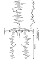
- Figure 4 is a graph showing a set of EMGdi signals of the diaphragm detected by pairs of successive electrodes of the array of Figure 2;
- Figure 5 is a flow chart showing a method for conducting double subtraction technique of the EMGdi signals;
- Figure 6 is a graph showing the distribution of correlation coefficients calculated for determining the position of the center of the depolarizing region of the diaphragm along the array of electrodes of Figure 2;
- Figure 7 is a schematic diagram illustrating in the time domain a double subtraction technique for improving the signal-to-noise ratioratio and to reduce an electrode-position-induced filter effect;
- Figure 8a is a graph showing the power density spectrum of electrode motion artifacts, the power density spectrum of ECG, and the power density spectrum of EMGdi signals;
- Figure 8b is a graph showing an example of transfer function for a filter to be used for filtering out the electrode motion artifacts, ECG, and the 50 or 60 Hz disturbance from electrical mains;
- Figure 9 is a schematic diagram illustrating in the frequency domain stabilization by the double subtraction technique of the center frequency upon displacement of the center of the depolarizing region of the diaphragm along the array of electrodes of Figure 2; and
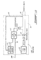
- Figure 10 is a schematic block diagram of a lung ventilator showing control of inspiratory proportional pressure assist ventilation by means of an EMG signal obtained with the above mentioned double subtraction technique.
-
- To measure EMG activity of the diaphragm 11 (EMGdi) of a
human patient 14, an array of electrodes such as 12 (Figures 1 and 2) are mounted on thefree end section 15 of anoesophageal catheter 13, with a constant inter-electrode distance d (Figure 2). As shown in Figure 1, thecatheter 13 is introduced into the patient's oesophagus through one nostril or the mouth until the array ofelectrodes 12 are situated at the level of the gastroesophageal junction. The diaphragm 11 and/or the oesophagus slightly move during breathing of the patient 14 whereby the array ofelectrodes 12 also slightly moves about the diaphragm 11. As will be explained in the following description, automatic compensation for this displacement is provided. - To mount an
electrode 12 on thefree end section 15 of thecatheter 13, stainless steel wire (not shown) may be wound around thecatheter 13. The wound stainless steel wire presents a rough surface smoothed out by solder, which in turn is electroplated with nickel, copper and then gold or silver. Of course, other constructions of electrodes can be implemented. - Electric wires (not shown) interconnect each pair of successive electrodes such as 1-7 (Figure 2) with a respective one of a group of
differential amplifiers 16. Obviously, these electric wires follow thecatheter 13 from therespective electrodes 12 to the correspondingamplifiers 16, and are preferably integrated to thecatheter 13. Preferably, the electric wires transmitting the EMGdi signals collected by the various pairs 1-7 ofelectrodes 12 are shielded to reduce the influence of external noise, in particular disturbance from the 50 or 60 Hz current and voltage of the electrical mains. - The group of
differential amplifiers 16 amplifies (first subtraction step of the double subtraction technique) and band-pass filters each EMGdi signal. This first subtraction step may also be carried out in thepersonnal computer 19 when theamplifiers 16 are single-ended or equivalently designed amplifiers (monopolar readings). - In the example illustrated in Figures 1 and 2, the
free end section 15 of thecatheter 13 is provided with an array of eightelectrodes 12 defining sevenpairs successive electrodes 12 respectively collecting seven different EMGdi signals. Although it has been found that EMG activity of the diaphragm (EMGdi) can be measured accurately with anoesophageal catheter 13 provided on thefree end section 15 thereof with an array of eightelectrodes 12, a different number and/or configuration of pairs ofelectrodes 12 can be contemplated depending on the patient's anatomy and movement of the diaphragm. Also, the pairs 1-7 do not need to be pairs of successive electrodes; Figure 3 illustrates an array of nine electrodes to form seven overlapping pairs of electrodes 1-7. - A major problem in recording EMGdi signals is to maintain the noise level as low and as constant as possible. Since the electric wires transmitting the EMGdi signals from the
electrodes 12 to thedifferential amplifiers 16 act as an antenna, it is crucial, as indicated in the foregoing description, to shield these electric wires to thereby protect the EMGdi signals from additional artifactual noise. Also, the package enclosing thedifferential amplifiers 16 is preferably made as small as possible (miniaturized) and is positioned in close proximity to the patient's nose to decrease as much as possible the distance between theelectrodes 12 and theamplifiers 16. - The amplified EMGdi signals are supplied to a
personal computer 19 through respective isolation amplifiers of aunit 18.Unit 18 supplies electric power to the various electronic components of the differential and isolation amplifiers while ensuring adequate isolation of the patient's body from such power supply. Theunit 18 also incorporates bandpass filters included in the respective EMGdi signal channels to eliminate the effects of aliasing. The EMGdi signals are then digitally processed into thepersonal computer 19 after analog-to-digital conversion thereof. This analog-to-digital conversion is conveniently carried out by an analog-to-digital converter implemented in thepersonal computer 19. Thepersonal computer 19 includes amonitor 40 and akeyboard 31. - It is believed to be within the capacity of those of ordinary skill in the art to construct suitable
differential amplifiers 16 and an adequate isolation amplifiers andpower supply unit 18. Accordingly, theamplifiers 16 and theunit 18 will not be further described in the present specification. - An example of the seven EMGdi signals collected by the pairs 1-7 of successive electrodes 12 (Figures 1 and 2) and supplied to the
computer 19 is illustrated in Figure 4. - As the diaphragm is generally perpendicular to the longitudinal axis of the
oesophageal catheter 13 equipped with an array ofelectrodes 12, only a portion of theelectrodes 12 are situated in the vicinity of the diaphragm. It is therefore important to determine the position of the diaphragm with respect to the oesophageal electrode array. - The portion of the crural diaphragm 11 which forms the muscular tunnel through which the
oesophageal catheter 13 is passed is referred to the "diaphragm depolarizing region" (DDR). The thickness of the DDR is 20-30 mm. It can be assumed that, within the DDR, the distribution of active muscle fibers has a center from which the majority of the EMGdi signals originate, i.e. the "diaphragm depolarizing region center" (DDR center). Therefore, EMGdi signals detected on opposite sides of the DDR center will be reversed in polarity with no phase shift; in other words, EMGdi signals obtained along the electrode array are reversing in polarity at the DDR center. - Moving centrally from the boundaries of the DDR, EMGdi power spectrums progressively attenuate and enhance in frequency. Reversal of signal polarity on either side of the
electrode pair 4 with the most attenuated power spectrum confirms the position from which the EMGdi signals originate, the DDR center. - Referring to Figure 5, the first task of the
computer 19 is to determine the center of the DDR. The center of the DDR is repeatedly determined at predetermined time intervals. - For that purpose, slow trend is first removed from each EMGdi signal (step 500). To carry out such trend removal, the processing conducted by the
computer 19 on each EMGdi signal is equivalent to high-pass filtering each EMGdi signal at a transition frequency of about 20 Hz. In particular,step 500 will remove the direct current component of the EMGdi signals to enable thecomputer 19 to evaluate the polarities of the EMGdi signals relative to each other. - In
step 501, the EMGdi signals are cross-correlated in pairs. As well known to those of ordinary skill in the art, cross-correlation is a statistical determination of the phase relationship between two signals and essentially calculates the similarity between two signals in terms of a correlation coefficient r (step 502). A negative correlation coefficient r indicates that the cross-correlated signals are of opposite polarities. - Figure 6 shows curves of the value of the correlation coefficient r versus the midpoint between the pairs of electrodes from which the correlated EMGdi signals originate. In this example, the inter-electrode distance is 10 mm. Curves are drawn for distances between the correlated pairs of
electrodes 12 of 5 mm (curve 20), 10 mm (curve 21), 15 mm (curve 22) and 20 mm (curve 23). One can appreciate from Figure 5 that negative correlation coefficient r are obtained when EMGdi signals from respective electrode pairs situated on opposite sides of theelectrode pair 4 are cross-correlated. It therefore appears that the change in polarity occur in the region ofelectrode pair 4, which is confirmed by the curves of Figure 4. Accordingly, it can be assumed that the center of the DDR is situated substantially midway between theelectrodes 12 formingpair 4. - For example, the center of the DDR can be precisely determined by interpolation (step 503 of Figure 5) using a square law based fit of the three most negative correlation coefficients of
curve 21 obtained by successive cross-correlation of the EMGdi signals from each electrode pair to the EMGdi signals from the second next electrode pair. Association of the center of the DDR to a pair ofelectrodes 12 provides a "reference position" from which to obtain EMGdi signals within the DDR. Such control is essential in overcoming the artifactual influence on the EMGdi power spectrum. - It has been experimentally demonstrated that EMGdi signals recorded in the oesophagus are satisfactory as long as they are obtained from electrode pairs (with an inter-electrode distance situated between 5 and 20 mm) positioned at a distance situated between 5 and 30 mm on the opposite sides of the DDR center (the inter-pair distance being therefore situated between 5 and 30 mm). Although EMGdi signals obtained from these positions offers a clear improvement in acceptance rate, the signal-to-noise ratio during quiet breathing still tends to remain unsatisfactorily low.
- For example, in Figure 4, the EMGdi signals originating from the electrode pairs 3 and 5 situated respectively 10 mm below and 10 mm above the DDR are strongly inversely correlated at zero time delay. In contrast to the inversely correlated EMGdi signals, the noise components for
electrode pairs electrode pairs - Subtraction step 504 (second subtraction step of the double subtraction technique) can be carried out either in the time domain, or after conversion of
signals electrode pair 2 from the EMGdi signal from electrode pair 5 (Figure 4), by subtracting signal fromelectrode pair 6 from the signal fromelectrode pair 3 and by adding these differences, etc. What is important is to subtract two signals of opposite polarities obtained in the vicinity of the muscle. - The double subtraction technique is carried out in
step 504 on the pair of EMGdi signals (for example the signals fromelectrode pairs step 503, after appropriate filtering of these EMGdi signals instep 505.Filtering step 505 will remove from each EMGdi signal the motion artifacts, the electrocardiogram (ECG) component, and the disturbance from the electrical mains. Motion artifacts are induced by motion of the electrodes. More generally, motion artifacts are defined as a low frequency fluctuation of the EMGdi signals' DC level induced by mechanical alterations of the electrode metal to electrolyte interface i.e. changes in electrode contact area and/or changes in pressure that the tissue exerts on the electrode. - The graph of Figure 8a shows the power density spectrum of the above defined electrode motion artifacts, the power density spectrum of ECG, and the power density spectrum of EMGdi signals. The graph of Figure 8b shows an example of transfer function for a filter (the dashed line showing the optimal transfer function, and the solid line the transfer function implemented by the inventors) to be used in
step 505 for filtering out the electrode motion artifacts, ECG, and the 50 or 60 Hz disturbance from the electrical mains. Processing of the EMGdi signals by thecomputer 19 to follow as closely as possible the optimal transfer function of Figure 8b will conduct adequately filteringstep 505. - Referring back to Figure 5,
step 506 calculates the RMS (Root-mean-square) value of the double-subtracted signal produced instep 504. The increase in amplitude obtained with the double subtraction technique is associated with a twofold increase in RMS values. RMS values obtained with the double subtraction technique are closely and linearly related to the original signals. The RMS value can be replaced by any other value representative of the strenght of the double-subtracted signal. - The digital RMS value calculated by the
computer 19 instep 506 is finally converted to an on-line analog RMS value (step 507) which is outputted online 508 in view of controlling a lung ventilator 54 (Figure 10). - The double subtraction technique compensates for the changes in signal strenght and frequency caused by movement of the diaphragm 11 (Figure 1) and/or the oesophagus during breathing of the patient 14 causing movement of the array of
electrodes 12 with respect to the diaphragm 11. Referring to Figure 9, off center of the array of electrodes 12 (electrode-position-induced filter effect) causes a variation of center frequency values (seecurves 27 and 28) for the EMGdi signals from the electrode pairs 3 and 5. The double subtraction technique eliminates such variation of center frequency values as indicated bycurve 29 as well as variation of signal strenght. Therefore, the reciprocal influence of the position of the DDR center on the EMGdi signal frequency content is eliminated by the double subtraction technique. - It has been found that the double subtraction technique may improve the signal-to-noise ratio by more than 2 dB ratio and reduce an electrode-position-induced filter effect. Double subtraction technique is also responsible for a relative increase in acceptance rate by more than 30%.
- Cross-talk signals from adjacent muscles are strongly correlated at zero time delay and equal in polarity between all pairs of
electrodes 12. Hence, these cross-talk signals appear as a common mode signal for all electrode pairs and therefore, are eliminated by the double subtraction technique. - Figure 10 illustrates a
lung ventilator 54 capable of being controlled by the analog RMS value of the double-subtracted signal produced instep 507 of Figure 5. Although an air-flow-based pressure ventilator is illustrated as an example in Figure 10, it should be kept in mind that the analog RMS value of the double subtracted signal can be used for controlling any other lung ventilator. -
Ventilator 54 shown in Figure 10 as an illustrative example only comprises aflow control unit 53, aflow pump 55, a patient's respiratory (inspiratory and expiratory) implement 56 such as a mask, a trachial tube connector, or any other respiratory implement, apressure sensor 57, a pressurizingvalve 58, and a depressurizingvalve 59. - The
flow pump 55 produces a constant air flow and supply of this air flow to the patient'srespiratory accessory 56 is controlled through the pressurizingvalve 58. The patient is allowed to breathe out through therespiratory accessory 56 and the depressurizingvalve 59. The pressurizing and depressurizingvalves flow control unit 53. - The
pressure sensor 57 is connected close to the respiratory implement 56 through aline 60. Thepressure sensor 57 produces a corresponding respiratory pressurerepresentative signal 61 supplied to theflow control unit 53. Accordingly, thepressure sensor 57 provides feedback of actual respiratory pressure close to the respiratory implement 56. Theflow control unit 53 is also supplied with theanalog RMS value 62 of the double-subtracted signal delivered online 508 bystep 507 of Figure 5. - Those of ordinary skill in the art know that the amplitude of the
analog RMS value 62 of the double-subtracted signal delivered online 508 is a representation of the demand to breathe from the brain. - When the
analog RMS value 62 supplied to theflow control unit 53 is higher than the amplitude of the pressurerepresentative signal 61, this indicates that the demand to breath from the brain is higher than the air actually breathed by the patient. Inspiratory assist is then required and theflow control unit 53 will open pressurizingvalve 58 to supply air flow from thepump 55 to the patient's respiratory accessory (depressurizingvalve 59 being closed) until the amplitude of the pressurerepresentative signal 61 is equal to theanalog RMS value 62. Theflow control unit 53 will continue to control the position ofvalve 58 to maintain the amplitude of the pressurerepresentative signal 61 equal to theanalog RMS value 62 during all the inspiratory cycle. - During the inspiratory cycle, when the
analog RMS value 62 falls slightly below the amplitude of the pressurerepresentative signal 61, depressurizingvalve 59 can be opened to correct the situation and maintain the amplitude of the pressurerepresentative signal 61 equal to theanalog RMS value 62. - When the
analog RMS value 62 drops below a given threshold, this indicates the beginning of an expiratory cycle. Then, theflow control unit 53closes pressurizing valve 58 and opens depressurizingvalve 59 to allow the patient to breath out through therespiratory accessory 56 and the depressurizingvalve 59. - In order to obtain correct proportionality between the pressure
representative signal 61 and theanalog RMS value 62, a gain adjustment is introduced for example insensor 57 or on theline 508 to adequately control pressure assist to the respiratory implement 56 in function of theanalog RMS value 62. - Accordingly, the subject invention presents a major advantage over the prior art. Indeed, the degree of inspiratory assist is adjusted in relation to the real need of the patient. In other words, assist is proportional to the difference between the pressure
representative signal 61 and theanalog RMS value 62. Inspiratory assist is therefore provided only to compensate for the degree of incapacity of the patient. The patient still contributes to inspiration as a function of his capacity to prevent the lung ventilator to further reduce the patient's inability to breathe. Requiring breathing efforts from the patient usually accelerates recovery of the patient and faster disconnection of the patient from the lung ventilator.
Claims (11)
- A device for controlling a lung ventilator (54) to assist inspiration of a patient (14), said lung ventilator comprising an inspiratory implement (56) to be worn by the patient, an air supply system (55, 58) for supplying air to the inspiratory implement in order to assist the patient's inspiration, and a control unit (53) for controlling the air supply system in relation to an input signal (508), characterised in that the device comprises:a series of electrodes (12) for detecting electromyographic signals produced by the patient's diaphragm (11) when said series of electrodes passes through the center of the patient's diaphragm depolarizing region, each electrode-detected electromyographic signal comprising an electromyographic component and a noise component;means (500-503) for determining the position of the center of the patient's diaphragm depolarizing region along the series of electrodes (12) by detecting a reversal of polarity of the electromyographic component of the electrode-detected electromyographic signals;means (504) for subtracting a first electromyographic signal detected by the electrodes of the series on a first side of the center of the patient's diaphragm depolarizing region, from a second electromyographic signal detected by the electrodes of the series on a second side, opposite to said first side, of the center of the patient's diaphragm depolarizing region, wherein (a) the first electrode-detected electromyographic signal has an electromyographic component of a first polarity, (b) the second electrode-detected electromyographic signal has an electromyographic component of a second polarity opposite to said first polarity, (c) the subtraction subtracts the noise components of the first and second electrode-detected electromyographic signals from each other but adds the respective electromyographic components of said first and second electrode-detected electromyographic signals together to produce an electromyographic signal of improved signal-to-noise ratio representative of a demand to inspire from the patient's brain; andmeans (506-508) for supplying said electromyographic signal of improved signal-to-noise ratio as an input signal to the control unit (53) of the lung ventilator (54) for controlling the air supply system (55, 58) and therefore the inspiration assist in relation to the electromyographic signal of improved signal-to-noise ratio.
- A device for controlling a lung ventilator as claimed in claim 1, characterised in that:(a) said series of electrodes (12) is a linear array of electrodes and defines a plurality of pairs (1-7) of successive electrodes; and,(b) when the center of the patient's diaphragm depolarizing region is located between the electrodes of a given one (4) of said pairs of successive electrodes (12) the device comprises(i) means for detecting said first electromyographic signal through the pair (5) of successive electrodes (12) adjacent to said given pair (4) on one side of said given pair; and(ii) means for detecting said second electromyographic signal through the pair (3) of successive electrodes (12) adjacent to said given pair (4) on the other side of said given pair.
- A device for controlling a lung ventilator as claimed in claim 1 or 2, characterised in that said center position determining means (500-503) comprises means (501) for cross-correlating the electrode-detected electromyographic signals.
- A device for controlling a lung ventilator as claimed in claim 3, characterised in that said center position determining means (500-503) comprises means (500) for removing a slow trend from the electrode-detected electromyographic signals prior to cross-correlating the electrode-detected electromyographic signals.
- A device for controlling a lung ventilator as claimed in any preceding claim, characterised in that said subtracting means (504) is a time domain subtracting means.
- A device for controlling a lung ventilator as claimed in any of claims 1 to 4, characterised in that said subtracting means (504) comprises means for converting said first and second electrode-detected electromyographic signals in the frequency domain before carrying out said subtraction.
- A device for controlling a lung ventilator as claimed in any preceding claim, characterised in that said electromyographic signal supplying means (506-508) comprises:means (506) for calculating a RMS value of the electromyographic signal of improved signal-to-noise ratio; andmeans (508) for supplying said RMS value as an input signal to the control unit (53) of the lung ventilator.
- A device for controlling a lung ventilator as claimed in any of claims 1 to 6, characterised in that said electromyographic signal supplying means (506-508) comprises:means (506) for calculating a RMS value of the electromyographic signal of improved signal-to-noise ratio;means (507) for digital-to-analog converting said RMS value;
andmeans (508) for supplying the analog RMS value as an input signal to the control unit (53) of the lung ventilator. - A device for controlling a lung ventilator as claimed in any preceding claim, characterised in that it further comprises means (505) for filtering from the electrode-detected electromyographic signals (i) motion artifacts, (ii) an ECG component, and (iii) a disturbance from electrical mains, prior to said subtraction of the first electrode-detected electromyographic signal from the second electrode-detected electromyographic signal.
- A device for controlling a lung ventilator as claimed in any preceding claim, characterised in that it further comprises:wherein said control unit is arranged to control the air supply system (55, 58) in relation to a difference between said pressure representative signal and said electromyographic signal of improved signal-to-noise ratio.means (57) for detecting the patient's respiratory pressure and for producing a pressure representative signal; andmeans for supplying the pressure representative signal to the control unit (53) of the lung ventilator;
- A device for controlling a lung ventilator as claimed in any preceding claim, characterised in that said series of electrodes is a linear array of electrodes (12) mounted on a free end section (15) of a catheter (13).
Applications Claiming Priority (3)
| Application Number | Priority Date | Filing Date | Title |
|---|---|---|---|
| US08/848,295 US5820560A (en) | 1995-03-31 | 1997-04-29 | Inspiratory proportional pressure assist ventilation controlled by a diaphragm electromyographic signal |
| US848295 | 1997-04-29 | ||
| PCT/CA1997/000515 WO1998048877A1 (en) | 1997-04-29 | 1997-07-17 | Inspiratory proportional pressure assist ventilation controlled by a diaphragm electromyographic signal |
Publications (2)
| Publication Number | Publication Date |
|---|---|
| EP0979118A1 EP0979118A1 (en) | 2000-02-16 |
| EP0979118B1 true EP0979118B1 (en) | 2003-06-25 |
Family
ID=25302906
Family Applications (1)
| Application Number | Title | Priority Date | Filing Date |
|---|---|---|---|
| EP97931601A Expired - Lifetime EP0979118B1 (en) | 1997-04-29 | 1997-07-17 | Device for inspiratory proportional pressure assist ventilation controlled by a diaphragm electromyographic signal |
Country Status (8)
| Country | Link |
|---|---|
| US (1) | US5820560A (en) |
| EP (1) | EP0979118B1 (en) |
| JP (2) | JP2001523127A (en) |
| AT (1) | ATE243543T1 (en) |
| AU (1) | AU3534497A (en) |
| CA (1) | CA2288098C (en) |
| DE (1) | DE69723113T2 (en) |
| WO (1) | WO1998048877A1 (en) |
Cited By (2)
| Publication number | Priority date | Publication date | Assignee | Title |
|---|---|---|---|---|
| WO2025116795A1 (en) * | 2023-11-29 | 2025-06-05 | Maquet Critical Care Ab | Training data for classification of a position of a catheter in relation to a diaphragm |
| WO2025116794A1 (en) * | 2023-11-29 | 2025-06-05 | Maquet Critical Care Ab | Classifying of a position of a catheter in relation to a diaphragm |
Families Citing this family (84)
| Publication number | Priority date | Publication date | Assignee | Title |
|---|---|---|---|---|
| US6588423B1 (en) * | 1998-02-27 | 2003-07-08 | Universite De Montreal | Method and device responsive to myoelectrical activity for triggering ventilatory support |
| US6259938B1 (en) * | 1998-05-15 | 2001-07-10 | Respironics, Inc. | Monitoring catheter and method of using same |
| CA2239673A1 (en) * | 1998-06-04 | 1999-12-04 | Christer Sinderby | Automatic adjustment of applied levels of ventilatory support and extrinsic peep by closed-loop control of neuro-ventilatory efficiency |
| US6411843B1 (en) * | 1999-05-28 | 2002-06-25 | Respironics, Inc. | Method and apparatus for producing a model EMG signal from a measured EMG signal |
| US6200272B1 (en) | 1999-06-08 | 2001-03-13 | Curative Health Services, Inc. | Folding card device for evaluating protective sensation |
| CA2276962A1 (en) * | 1999-07-07 | 2001-01-07 | Universite De Montreal | Electromyogram signal analysis method and system for use with electrode array |
| US6962155B1 (en) * | 1999-07-30 | 2005-11-08 | Universite De Montreal | Target drive ventilation gain controller and method |
| SE0004141D0 (en) * | 2000-11-13 | 2000-11-13 | Siemens Elema Ab | Method of adaptive triggering of breathing devices and a breathing device |
| JP4885416B2 (en) * | 2001-01-16 | 2012-02-29 | ユニヴェルシテ・ドゥ・モントリオール | Myoelectrically activated respiratory leak seal |
| US6584345B2 (en) * | 2001-03-13 | 2003-06-24 | Biosense, Inc. | Apparatus and method for measuring a plurality of electrical signals from the body of a patient |
| SE0203108D0 (en) * | 2002-10-22 | 2002-10-22 | Siemens Elema Ab | Multi-Electrode Catheter |
| RU2246926C2 (en) * | 2002-12-19 | 2005-02-27 | Московский областной научно-исследовательский клинический институт (МОНИКИ) | Apparatus for carrying out artificial lung ventilation |
| US7184812B2 (en) * | 2003-05-13 | 2007-02-27 | Maquet Critical Care Ab | Control of inter-electrode resistivity to improve quality of measured electrical biological signals |
| EP1680167B1 (en) * | 2003-10-23 | 2014-07-16 | Maquet Critical Care AB | Combined positive and negative pressure assist ventilation |
| SE0303062L (en) * | 2003-11-19 | 2005-05-20 | Maquet Critical Care Ab | Method and device for filtering out an EMG signal |
| SE0303061D0 (en) * | 2003-11-19 | 2003-11-19 | Maquet Critical Care Ab | Method and apparatus for determining an EMG signal |
| US20050159659A1 (en) * | 2004-01-16 | 2005-07-21 | Mohamad Sawan | Catheter for transdiaphragmatic pressure and diaphragm electromyogram recording using helicoidal electrodes |
| US7472702B2 (en) * | 2004-03-25 | 2009-01-06 | Maquet Critical Care Ab | Method and device responsive to diaphragmatic activity for adjusting positive pressure assist during expiration |
| CN101137324B (en) * | 2005-01-12 | 2012-10-31 | 马奎特紧急护理公司 | Electrode for physiological signal measurements and method for making same |
| US20060259464A1 (en) * | 2005-05-10 | 2006-11-16 | Szczublewski Francis E | Selection of audio categories and files in entertainment system |
| US8784336B2 (en) | 2005-08-24 | 2014-07-22 | C. R. Bard, Inc. | Stylet apparatuses and methods of manufacture |
| JP5264506B2 (en) | 2006-01-19 | 2013-08-14 | マケット・クリティカル・ケア・アーベー | Device for dynamically determining respiratory characteristics of spontaneously breathing patients receiving mechanical breathing assistance |
| CN101460088B (en) * | 2006-06-02 | 2011-06-15 | 皇家飞利浦电子股份有限公司 | Biofeedback system and display device |
| CN101657152B (en) * | 2007-04-27 | 2012-10-31 | 马奎特紧急护理公司 | An EMG controlled ventilator and a method for an EMG controlled ventilator |
| EP2148712B1 (en) * | 2007-04-27 | 2018-10-31 | Maquet Critical Care AB | Control unit and display unit for an emg controlled ventilator |
| FR2921245B1 (en) * | 2007-09-25 | 2009-12-04 | Univ Joseph Fourier | RESPIRATORY DIAGNOSTIC DEVICE |
| US8527036B2 (en) * | 2007-09-28 | 2013-09-03 | Maquet Critical Care Ab | Catheter positioning method and computerized control unit for implementing the method |
| US8251903B2 (en) * | 2007-10-25 | 2012-08-28 | Valencell, Inc. | Noninvasive physiological analysis using excitation-sensor modules and related devices and methods |
| US9649048B2 (en) | 2007-11-26 | 2017-05-16 | C. R. Bard, Inc. | Systems and methods for breaching a sterile field for intravascular placement of a catheter |
| US10751509B2 (en) | 2007-11-26 | 2020-08-25 | C. R. Bard, Inc. | Iconic representations for guidance of an indwelling medical device |
| US9521961B2 (en) | 2007-11-26 | 2016-12-20 | C. R. Bard, Inc. | Systems and methods for guiding a medical instrument |
| US8781555B2 (en) | 2007-11-26 | 2014-07-15 | C. R. Bard, Inc. | System for placement of a catheter including a signal-generating stylet |
| ES2557084T3 (en) | 2007-11-26 | 2016-01-21 | C. R. Bard, Inc. | Integrated system for intravascular catheter placement |
| DE102007062214C5 (en) * | 2007-12-21 | 2017-12-21 | Drägerwerk AG & Co. KGaA | Method for automatically controlling a respiratory system and associated ventilator |
| ES2525525T3 (en) | 2008-08-22 | 2014-12-26 | C.R. Bard, Inc. | Catheter assembly that includes ECG and magnetic sensor assemblies |
| EP2320793B1 (en) | 2008-08-28 | 2020-12-16 | St. Michael's Hospital | Determining patient- ventilator breath contribution index in spontaneously breathing, mechanically ventilated patients |
| WO2010036816A1 (en) | 2008-09-25 | 2010-04-01 | Nellcor Puritan Bennett Llc | Inversion-based feed-forward compensation of inspiratory trigger dynamics in medical ventilators |
| US8280498B2 (en) * | 2008-11-13 | 2012-10-02 | Maquet Critical Care Ab | Method, ventilator and control unit for determining a position of an esophageal catheter |
| US8881725B2 (en) * | 2009-01-15 | 2014-11-11 | St. Michael's Hospital | Method and device for determining a level of ventilatory assist to a patient |
| US9179861B2 (en) | 2009-01-16 | 2015-11-10 | St. Michael's Hospital | Method for measuring changes in inspiratory load |
| US9532724B2 (en) | 2009-06-12 | 2017-01-03 | Bard Access Systems, Inc. | Apparatus and method for catheter navigation using endovascular energy mapping |
| JP5281508B2 (en) * | 2009-07-22 | 2013-09-04 | 株式会社医器研 | Oxygen concentrator and method for determining inspection time of oxygen concentrator |
| EP2464407A4 (en) | 2009-08-10 | 2014-04-02 | Bard Access Systems Inc | DEVICES AND METHODS FOR ENDOVASCULAR ELECTROGRAPHY |
| WO2011097312A1 (en) | 2010-02-02 | 2011-08-11 | C.R. Bard, Inc. | Apparatus and method for catheter navigation and tip location |
| JP5445263B2 (en) * | 2010-03-24 | 2014-03-19 | セイコーエプソン株式会社 | Biological information acquisition device |
| EP2628497B1 (en) | 2010-03-30 | 2016-10-12 | Drägerwerk AG & Co. KGaA | Ventilation and anaesthetic system |
| EP2912999B1 (en) | 2010-05-28 | 2022-06-29 | C. R. Bard, Inc. | Apparatus for use with needle insertion guidance system |
| CN103037761B (en) | 2010-05-28 | 2016-11-02 | C·R·巴德股份有限公司 | Insertion guide systems for needles and medical components |
| CN103079621B (en) * | 2010-06-30 | 2015-09-16 | 圣米高医院 | For the method and system that the ventilation synchronous with patient by tracheal strips through-flow is auxiliary |
| JP5845260B2 (en) | 2010-08-20 | 2016-01-20 | シー・アール・バード・インコーポレーテッドC R Bard Incorporated | Reconfirmation of ECG support catheter tip placement |
| DE102010055253B4 (en) | 2010-12-20 | 2016-11-10 | Drägerwerk AG & Co. KGaA | Automatically controlled ventilator |
| DE102011016804B4 (en) | 2011-04-12 | 2016-01-28 | Drägerwerk AG & Co. KGaA | Device and method for data processing of physiological signals |
| EP3222210B1 (en) | 2011-08-02 | 2024-09-25 | Yukka Magic LLC | Systems and methods for variable filter adjustment by heart rate metric feedback |
| EP2776101B1 (en) * | 2011-11-07 | 2017-05-17 | ResMed Limited | Apparatus for providing ventilation to a patient |
| DE102012003509B4 (en) * | 2012-02-22 | 2020-06-10 | Drägerwerk AG & Co. KGaA | Respiratory system |
| ITMI20120428A1 (en) * | 2012-03-19 | 2013-09-20 | Giacomo Bellani | APPARATUS FOR ASSISTED VENTILATION AND ITS ADJUSTMENT METHOD |
| WO2015047168A1 (en) | 2013-09-25 | 2015-04-02 | Maquet Critical Care Ab | Neurally triggered support ventilation during hfo ventilation |
| EP3086831B1 (en) | 2013-12-27 | 2020-09-23 | St. Michael's Hospital | System for providing ventilatory assist to a patient |
| CN105979868B (en) | 2014-02-06 | 2020-03-10 | C·R·巴德股份有限公司 | Systems and methods for guidance and placement of endovascular devices |
| KR101678545B1 (en) * | 2014-08-12 | 2016-11-23 | 전남대학교산학협력단 | An endotracheal intubation system enabling verification of tube position using electrical stimulatio |
| WO2016060596A1 (en) | 2014-10-16 | 2016-04-21 | Maquet Critical Care Ab | Modular monitoring and ventilation system |
| US10973584B2 (en) | 2015-01-19 | 2021-04-13 | Bard Access Systems, Inc. | Device and method for vascular access |
| CN112076368B (en) | 2015-03-26 | 2024-02-20 | 马奎特紧急护理公司 | System and computer readable storage medium for use in connection with mechanical ventilation of a patient |
| WO2016210325A1 (en) | 2015-06-26 | 2016-12-29 | C.R. Bard, Inc. | Connector interface for ecg-based catheter positioning system |
| US10758693B2 (en) | 2015-09-10 | 2020-09-01 | St. Michael's Hospital. | Method and system for adjusting a level of ventilatory assist to a patient |
| US10945618B2 (en) | 2015-10-23 | 2021-03-16 | Valencell, Inc. | Physiological monitoring devices and methods for noise reduction in physiological signals based on subject activity type |
| EP3344127A4 (en) | 2015-10-23 | 2018-07-25 | Valencell, Inc. | Physiological monitoring devices and methods that identify subject activity type |
| DE102015014106A1 (en) * | 2015-11-03 | 2017-05-04 | Drägerwerk AG & Co. KGaA | Device for pressure-assisted or pressure-controlled ventilation of a patient with limited spontaneous breathing |
| US11000207B2 (en) | 2016-01-29 | 2021-05-11 | C. R. Bard, Inc. | Multiple coil system for tracking a medical device |
| US10966662B2 (en) | 2016-07-08 | 2021-04-06 | Valencell, Inc. | Motion-dependent averaging for physiological metric estimating systems and methods |
| EP3532137B1 (en) | 2016-10-27 | 2022-05-25 | Maquet Critical Care AB | Bioelectrically controlled ventilation |
| KR101806743B1 (en) | 2016-10-28 | 2017-12-07 | 영남대학교 산학협력단 | Respiratory muscle strengthening device |
| WO2018106164A1 (en) | 2016-12-08 | 2018-06-14 | Maquet Critical Care Ab | System for co2 removal |
| US11331445B2 (en) | 2017-02-03 | 2022-05-17 | Maquet Critical Care Ab | Determination of neuromuscular efficiency during mechanical ventilation |
| JP6876324B2 (en) * | 2017-02-21 | 2021-05-26 | 国立大学法人電気通信大学 | Signal measuring device and signal measuring method |
| EP3589343B1 (en) | 2017-03-01 | 2021-04-28 | Maquet Critical Care AB | System for detection of leakage or abnormal resistance in a ventilation system |
| US12420037B2 (en) | 2018-09-19 | 2025-09-23 | Unity Health Toronto | Systems, devices and methods for modulating a respiratory drive of a patient |
| EP3852622B1 (en) | 2018-10-16 | 2025-04-02 | Bard Access Systems, Inc. | Safety-equipped connection systems and methods thereof for establishing electrical connections |
| CN113473916A (en) | 2019-01-30 | 2021-10-01 | 巴德阿克塞斯系统股份有限公司 | System and method for tracking medical devices |
| WO2021179066A1 (en) | 2020-03-09 | 2021-09-16 | Christer Sinderby | Method and system for controlling a level of ventilatory assist applied to a patient by a mechanical ventilator |
| DE102022101845A1 (en) | 2021-06-18 | 2022-12-22 | Drägerwerk AG & Co. KGaA | Ventilation device, method, computer program and device for determining a measure of an intrinsic end-expiratory pressure |
| WO2023057691A1 (en) | 2021-10-08 | 2023-04-13 | Institut National de la Santé et de la Recherche Médicale | Multimodal method for detecting a change in a patient's physiological condition and device for monitoring a patient so as to implement such a method |
| CN114028671A (en) * | 2021-11-04 | 2022-02-11 | 湖南万脉医疗科技有限公司 | Control triggering method for respirator |
| US12420045B2 (en) | 2022-03-15 | 2025-09-23 | GE Precision Healthcare LLC | System and method for patient-ventilator synchronization/onset detection utilizing time-frequency analysis of EMG signals |
Family Cites Families (12)
| Publication number | Priority date | Publication date | Assignee | Title |
|---|---|---|---|---|
| NL183221C (en) * | 1978-03-20 | 1988-09-01 | Univ Groningen | DEVICE FOR DETECTING THE ACTIVITY OF THE BREATHING AGENTS AND THE HEART OF A LIVING BEING. |
| US4213467A (en) * | 1978-08-11 | 1980-07-22 | Harvard College, President And Fellows | Monitoring myoelectric signals |
| US5107831A (en) * | 1989-06-19 | 1992-04-28 | Bear Medical Systems, Inc. | Ventilator control system using sensed inspiratory flow rate |
| US5239995A (en) * | 1989-09-22 | 1993-08-31 | Respironics, Inc. | Sleep apnea treatment apparatus |
| CA2038971C (en) * | 1990-03-30 | 1996-06-18 | Magdy Younes | Lung ventilator device |
| US5212476A (en) * | 1990-09-28 | 1993-05-18 | Maloney Sean R | Wireless intraoral controller disposed in oral cavity with electrodes to sense E.M.G. signals produced by contraction of the tongue |
| DE4122069A1 (en) * | 1991-07-04 | 1993-01-07 | Draegerwerk Ag | METHOD FOR DETECTING A PATIENT'S BREATHING PHASES IN ASSISTANT VENTILATION METHODS |
| US5520192A (en) * | 1991-12-23 | 1996-05-28 | Imperial College Of Science, Technology And Medicine | Apparatus for the monitoring and control of respiration |
| US5353788A (en) * | 1992-09-21 | 1994-10-11 | Miles Laughton E | Cardio-respiratory control and monitoring system for determining CPAP pressure for apnea treatment |
| US5349963A (en) * | 1993-08-06 | 1994-09-27 | Sanhill Oy | Method and apparatus for measuring muscle fatigue |
| US5671752A (en) * | 1995-03-31 | 1997-09-30 | Universite De Montreal/The Royal Insitution For The Advancement Of Learning (Mcgill University) | Diaphragm electromyography analysis method and system |
| US5513631A (en) * | 1995-07-21 | 1996-05-07 | Infrasonics, Inc. | Triggering of patient ventilator responsive to a precursor signal |
-
1997
- 1997-04-29 US US08/848,295 patent/US5820560A/en not_active Expired - Lifetime
- 1997-07-17 CA CA002288098A patent/CA2288098C/en not_active Expired - Lifetime
- 1997-07-17 EP EP97931601A patent/EP0979118B1/en not_active Expired - Lifetime
- 1997-07-17 AT AT97931601T patent/ATE243543T1/en not_active IP Right Cessation
- 1997-07-17 AU AU35344/97A patent/AU3534497A/en not_active Abandoned
- 1997-07-17 WO PCT/CA1997/000515 patent/WO1998048877A1/en not_active Ceased
- 1997-07-17 DE DE69723113T patent/DE69723113T2/en not_active Expired - Lifetime
- 1997-07-17 JP JP54642298A patent/JP2001523127A/en not_active Withdrawn
-
2006
- 2006-05-02 JP JP2006128416A patent/JP4417922B2/en not_active Expired - Lifetime
Cited By (3)
| Publication number | Priority date | Publication date | Assignee | Title |
|---|---|---|---|---|
| WO2025116795A1 (en) * | 2023-11-29 | 2025-06-05 | Maquet Critical Care Ab | Training data for classification of a position of a catheter in relation to a diaphragm |
| WO2025116794A1 (en) * | 2023-11-29 | 2025-06-05 | Maquet Critical Care Ab | Classifying of a position of a catheter in relation to a diaphragm |
| US12396927B2 (en) | 2023-11-29 | 2025-08-26 | Maquet Critical Care Ab | Classifying of a position of a catheter in relation to a diaphragm |
Also Published As
| Publication number | Publication date |
|---|---|
| DE69723113D1 (en) | 2003-07-31 |
| EP0979118A1 (en) | 2000-02-16 |
| ATE243543T1 (en) | 2003-07-15 |
| CA2288098A1 (en) | 1998-11-05 |
| JP2001523127A (en) | 2001-11-20 |
| DE69723113T2 (en) | 2004-05-13 |
| JP2006239446A (en) | 2006-09-14 |
| AU3534497A (en) | 1998-11-24 |
| CA2288098C (en) | 2007-04-17 |
| WO1998048877A1 (en) | 1998-11-05 |
| JP4417922B2 (en) | 2010-02-17 |
| US5820560A (en) | 1998-10-13 |
Similar Documents
| Publication | Publication Date | Title |
|---|---|---|
| US5820560A (en) | Inspiratory proportional pressure assist ventilation controlled by a diaphragm electromyographic signal | |
| CA2379671C (en) | Target drive ventilation gain controller and method | |
| EP1382294B1 (en) | Proportional pressure assist ventilation controlled by a diaphragm electromyographic signal | |
| EP1056499B1 (en) | Device responsive to myoelectrical activity for triggering ventilatory support | |
| US7963283B2 (en) | Myoelectrically activated respiratory leak sealing | |
| US6901286B1 (en) | Method and system for producing a higher quality electromyographic signal from an electrode array | |
| CA2375591C (en) | Method and system for producing a higher quality electromyographic signal from an electrode array |
Legal Events
| Date | Code | Title | Description |
|---|---|---|---|
| PUAI | Public reference made under article 153(3) epc to a published international application that has entered the european phase |
Free format text: ORIGINAL CODE: 0009012 |
|
| 17P | Request for examination filed |
Effective date: 19991029 |
|
| AK | Designated contracting states |
Kind code of ref document: A1 Designated state(s): AT BE CH DE DK ES FI FR GB GR IE IT LI LU MC NL PT SE |
|
| 17Q | First examination report despatched |
Effective date: 20020301 |
|
| GRAH | Despatch of communication of intention to grant a patent |
Free format text: ORIGINAL CODE: EPIDOS IGRA |
|
| RTI1 | Title (correction) |
Free format text: DEVICE FOR INSPIRATORY PROPORTIONAL PRESSURE ASSIST VENTILATION CONTROLLED BY A DIAPHRAGM ELECTROMYOGRAPHIC SIGNAL |
|
| RTI1 | Title (correction) |
Free format text: DEVICE FOR INSPIRATORY PROPORTIONAL PRESSURE ASSIST VENTILATION CONTROLLED BY A DIAPHRAGM ELECTROMYOGRAPHIC SIGNAL |
|
| GRAH | Despatch of communication of intention to grant a patent |
Free format text: ORIGINAL CODE: EPIDOS IGRA |
|
| GRAA | (expected) grant |
Free format text: ORIGINAL CODE: 0009210 |
|
| AK | Designated contracting states |
Designated state(s): AT BE CH DE DK ES FI FR GB GR IE IT LI LU MC NL PT SE |
|
| PG25 | Lapsed in a contracting state [announced via postgrant information from national office to epo] |
Ref country code: NL Free format text: LAPSE BECAUSE OF FAILURE TO SUBMIT A TRANSLATION OF THE DESCRIPTION OR TO PAY THE FEE WITHIN THE PRESCRIBED TIME-LIMIT Effective date: 20030625 Ref country code: LI Free format text: LAPSE BECAUSE OF FAILURE TO SUBMIT A TRANSLATION OF THE DESCRIPTION OR TO PAY THE FEE WITHIN THE PRESCRIBED TIME-LIMIT Effective date: 20030625 Ref country code: IT Free format text: LAPSE BECAUSE OF FAILURE TO SUBMIT A TRANSLATION OF THE DESCRIPTION OR TO PAY THE FEE WITHIN THE PRESCRIBED TIME-LIMIT;WARNING: LAPSES OF ITALIAN PATENTS WITH EFFECTIVE DATE BEFORE 2007 MAY HAVE OCCURRED AT ANY TIME BEFORE 2007. THE CORRECT EFFECTIVE DATE MAY BE DIFFERENT FROM THE ONE RECORDED. Effective date: 20030625 Ref country code: FI Free format text: LAPSE BECAUSE OF FAILURE TO SUBMIT A TRANSLATION OF THE DESCRIPTION OR TO PAY THE FEE WITHIN THE PRESCRIBED TIME-LIMIT Effective date: 20030625 Ref country code: CH Free format text: LAPSE BECAUSE OF FAILURE TO SUBMIT A TRANSLATION OF THE DESCRIPTION OR TO PAY THE FEE WITHIN THE PRESCRIBED TIME-LIMIT Effective date: 20030625 Ref country code: BE Free format text: LAPSE BECAUSE OF FAILURE TO SUBMIT A TRANSLATION OF THE DESCRIPTION OR TO PAY THE FEE WITHIN THE PRESCRIBED TIME-LIMIT Effective date: 20030625 Ref country code: AT Free format text: LAPSE BECAUSE OF FAILURE TO SUBMIT A TRANSLATION OF THE DESCRIPTION OR TO PAY THE FEE WITHIN THE PRESCRIBED TIME-LIMIT Effective date: 20030625 |
|
| REG | Reference to a national code |
Ref country code: GB Ref legal event code: FG4D |
|
| REG | Reference to a national code |
Ref country code: CH Ref legal event code: EP |
|
| PG25 | Lapsed in a contracting state [announced via postgrant information from national office to epo] |
Ref country code: LU Free format text: LAPSE BECAUSE OF NON-PAYMENT OF DUE FEES Effective date: 20030717 Ref country code: IE Free format text: LAPSE BECAUSE OF NON-PAYMENT OF DUE FEES Effective date: 20030717 |
|
| REG | Reference to a national code |
Ref country code: IE Ref legal event code: FG4D |
|
| PG25 | Lapsed in a contracting state [announced via postgrant information from national office to epo] |
Ref country code: MC Free format text: LAPSE BECAUSE OF NON-PAYMENT OF DUE FEES Effective date: 20030731 |
|
| REF | Corresponds to: |
Ref document number: 69723113 Country of ref document: DE Date of ref document: 20030731 Kind code of ref document: P |
|
| PG25 | Lapsed in a contracting state [announced via postgrant information from national office to epo] |
Ref country code: SE Free format text: LAPSE BECAUSE OF FAILURE TO SUBMIT A TRANSLATION OF THE DESCRIPTION OR TO PAY THE FEE WITHIN THE PRESCRIBED TIME-LIMIT Effective date: 20030925 Ref country code: PT Free format text: LAPSE BECAUSE OF FAILURE TO SUBMIT A TRANSLATION OF THE DESCRIPTION OR TO PAY THE FEE WITHIN THE PRESCRIBED TIME-LIMIT Effective date: 20030925 Ref country code: GR Free format text: LAPSE BECAUSE OF FAILURE TO SUBMIT A TRANSLATION OF THE DESCRIPTION OR TO PAY THE FEE WITHIN THE PRESCRIBED TIME-LIMIT Effective date: 20030925 Ref country code: GB Free format text: LAPSE BECAUSE OF NON-PAYMENT OF DUE FEES Effective date: 20030925 Ref country code: DK Free format text: LAPSE BECAUSE OF FAILURE TO SUBMIT A TRANSLATION OF THE DESCRIPTION OR TO PAY THE FEE WITHIN THE PRESCRIBED TIME-LIMIT Effective date: 20030925 |
|
| NLV1 | Nl: lapsed or annulled due to failure to fulfill the requirements of art. 29p and 29m of the patents act | ||
| PG25 | Lapsed in a contracting state [announced via postgrant information from national office to epo] |
Ref country code: ES Free format text: LAPSE BECAUSE OF FAILURE TO SUBMIT A TRANSLATION OF THE DESCRIPTION OR TO PAY THE FEE WITHIN THE PRESCRIBED TIME-LIMIT Effective date: 20031222 |
|
| REG | Reference to a national code |
Ref country code: CH Ref legal event code: PL |
|
| ET | Fr: translation filed | ||
| PLBE | No opposition filed within time limit |
Free format text: ORIGINAL CODE: 0009261 |
|
| STAA | Information on the status of an ep patent application or granted ep patent |
Free format text: STATUS: NO OPPOSITION FILED WITHIN TIME LIMIT |
|
| REG | Reference to a national code |
Ref country code: IE Ref legal event code: MM4A |
|
| GBPC | Gb: european patent ceased through non-payment of renewal fee |
Effective date: 20030925 |
|
| 26N | No opposition filed |
Effective date: 20040326 |
|
| REG | Reference to a national code |
Ref country code: DE Ref legal event code: R082 Ref document number: 69723113 Country of ref document: DE Representative=s name: CALLIES, RAINER, DIPL.-PHYS. DR.RER.NAT., DE Ref country code: DE Ref legal event code: R082 Ref document number: 69723113 Country of ref document: DE Representative=s name: RAINER CALLIES, DE |
|
| REG | Reference to a national code |
Ref country code: FR Ref legal event code: PLFP Year of fee payment: 20 |
|
| PGFP | Annual fee paid to national office [announced via postgrant information from national office to epo] |
Ref country code: DE Payment date: 20160712 Year of fee payment: 20 |
|
| PGFP | Annual fee paid to national office [announced via postgrant information from national office to epo] |
Ref country code: FR Payment date: 20160712 Year of fee payment: 20 |
|
| REG | Reference to a national code |
Ref country code: DE Ref legal event code: R071 Ref document number: 69723113 Country of ref document: DE |