EP0978769A1 - A method of printing in a device for direct electrostatic printing comprising a toner delivery means that comprises a charged toner conveying roll, a magnetic brush and a cleaning unit - Google Patents
A method of printing in a device for direct electrostatic printing comprising a toner delivery means that comprises a charged toner conveying roll, a magnetic brush and a cleaning unit Download PDFInfo
- Publication number
- EP0978769A1 EP0978769A1 EP98202607A EP98202607A EP0978769A1 EP 0978769 A1 EP0978769 A1 EP 0978769A1 EP 98202607 A EP98202607 A EP 98202607A EP 98202607 A EP98202607 A EP 98202607A EP 0978769 A1 EP0978769 A1 EP 0978769A1
- Authority
- EP
- European Patent Office
- Prior art keywords
- toner particles
- toner
- charged
- printing
- magnetic
- Prior art date
- Legal status (The legal status is an assumption and is not a legal conclusion. Google has not performed a legal analysis and makes no representation as to the accuracy of the status listed.)
- Withdrawn
Links
Images

Classifications
-
- G—PHYSICS
- G03—PHOTOGRAPHY; CINEMATOGRAPHY; ANALOGOUS TECHNIQUES USING WAVES OTHER THAN OPTICAL WAVES; ELECTROGRAPHY; HOLOGRAPHY
- G03G—ELECTROGRAPHY; ELECTROPHOTOGRAPHY; MAGNETOGRAPHY
- G03G15/00—Apparatus for electrographic processes using a charge pattern
- G03G15/22—Apparatus for electrographic processes using a charge pattern involving the combination of more than one step according to groups G03G13/02 - G03G13/20
- G03G15/34—Apparatus for electrographic processes using a charge pattern involving the combination of more than one step according to groups G03G13/02 - G03G13/20 in which the powder image is formed directly on the recording material, e.g. by using a liquid toner
- G03G15/344—Apparatus for electrographic processes using a charge pattern involving the combination of more than one step according to groups G03G13/02 - G03G13/20 in which the powder image is formed directly on the recording material, e.g. by using a liquid toner by selectively transferring the powder to the recording medium, e.g. by using a LED array
- G03G15/346—Apparatus for electrographic processes using a charge pattern involving the combination of more than one step according to groups G03G13/02 - G03G13/20 in which the powder image is formed directly on the recording material, e.g. by using a liquid toner by selectively transferring the powder to the recording medium, e.g. by using a LED array by modulating the powder through holes or a slit
-
- G—PHYSICS
- G03—PHOTOGRAPHY; CINEMATOGRAPHY; ANALOGOUS TECHNIQUES USING WAVES OTHER THAN OPTICAL WAVES; ELECTROGRAPHY; HOLOGRAPHY
- G03G—ELECTROGRAPHY; ELECTROPHOTOGRAPHY; MAGNETOGRAPHY
- G03G15/00—Apparatus for electrographic processes using a charge pattern
- G03G15/06—Apparatus for electrographic processes using a charge pattern for developing
- G03G15/08—Apparatus for electrographic processes using a charge pattern for developing using a solid developer, e.g. powder developer
- G03G15/0806—Apparatus for electrographic processes using a charge pattern for developing using a solid developer, e.g. powder developer on a donor element, e.g. belt, roller
- G03G15/0815—Apparatus for electrographic processes using a charge pattern for developing using a solid developer, e.g. powder developer on a donor element, e.g. belt, roller characterised by the developer handling means after the developing zone and before the supply, e.g. developer recovering roller
-
- G—PHYSICS
- G03—PHOTOGRAPHY; CINEMATOGRAPHY; ANALOGOUS TECHNIQUES USING WAVES OTHER THAN OPTICAL WAVES; ELECTROGRAPHY; HOLOGRAPHY
- G03G—ELECTROGRAPHY; ELECTROPHOTOGRAPHY; MAGNETOGRAPHY
- G03G2217/00—Details of electrographic processes using patterns other than charge patterns
- G03G2217/0008—Process where toner image is produced by controlling which part of the toner should move to the image- carrying member
- G03G2217/0025—Process where toner image is produced by controlling which part of the toner should move to the image- carrying member where the toner starts moving from behind the electrode array, e.g. a mask of holes
Abstract
A method for Direct Electrostatic Printing (DEP) is provided
comprising the steps of :
- bringing charged toner particles from a magnetic brush carrying magnetic carrier particles and non magnetic toner particles to a toner bearing surface of a conveyer for charged toner,
- applying an electrical potential difference between the toner bearing surface and an image receiving member, for creating a flow of charged toner particles from the surface bearing charged toner particles to the image receiving member,
- placing a printhead structure having printing apertures and control electrodes in the flow, forming a development zone under the printing apertures for image wise depositing toner particles, from the flow of charged toner particles, on the image receiving member
- moving the conveyer for charged toner particles to pass the toner bearing surface repeatedly through the development zone, in a direction so as to have the magnetic brush upstream of the development zone and
- removing, downstream from the development zone, non-used toner particles from the toner bearing surface and collecting them.
Description
This invention relates to a recording method and an apparatus
for use in the process of Direct Electrostatic Printing (DEP), in
which an image is created upon a receiving substrate by creating a
flow of toner particles from a toner bearing surface to the image
receiving substrate and image-wise modulating the flow of toner
particles by means of an electronically addressable printhead
structure.
In DEP (Direct Electrostatic Printing) toner particles are
deposited directly in an image-wise way on a receiving substrate,
the latter not bearing any image-wise latent electrostatic image.
This makes the method different from classical electrography, in
which a latent electrostatic image on a charge retentive surface is
developed by a suitable material to make the latent image visible,
or from electrophotography in which an additional step and
additional member is introduced to create the latent electrostatic
image (photoconductor and charging/exposure cycle).
A DEP device is disclosed in e.g. US-A-3 689 935. This document
discloses an electrostatic line printer having a multi-layered
particle modulator or printhead structure comprising :
- a layer of insulating material, called isolation layer ;
- a shield electrode consisting of a continuous layer of conductive material on one side of the isolation layer ;
- a plurality of control electrodes formed by a segmented layer of conductive material on the other side of the isolation layer ; and
- at least one row of apertures.
Each control electrode is formed around one aperture and is
isolated from each other control electrode.
Selected electric potentials are applied to each of the control
electrodes while a fixed potential is applied to the shield
electrode. An overall applied propulsion field between a toner
delivery means and a support for a toner receiving substrate
projects charged toner particles through a row of apertures of the
printhead structure. The intensity of the particle stream is
modulated according to the pattern of potentials applied to the
control electrodes. The modulated stream of charged particles
impinges upon a receiving substrate, interposed in the modulated
particle stream. The receiving substrate is transported in a
direction perpendicular to the printhead structure, to provide a
line-by-line scan printing. The shield electrode may face the toner
delivery means and the control electrodes may face the receiving
substrate. A DC-field is applied between the printhead structure and
a single back electrode on the receiving substrate. This propulsion
field is responsible for the attraction of toner to the receiving
substrate that is placed between the printhead structure and the
back electrode.
One of the problems with this type of printing devices is that
charged toner particles can accumulate upon the printhead structure
and in the printing apertures. Due to this problem the achievable
printing density does not remain constant in the time, while the
charged toner particles accumulated on the printhead structure may
change the electrical field wherein the charged toner particles are
propelled towards the substrate and the toner particles accumulated
in the printing apertures can physically block the toner passage.
Several disclosures concerning devices that can clean up a
printhead structure after it has been smudged with toner particles
are known in the art.
In other disclosures, ways and means are disclosed to prevent
the smudging of the printhead structure in the first place.). In,
e.g., US-A-4 755 837 and US-A-4 814 796 it is disclosed that the
presence of Wrong Sign Toner (WST) is the main cause of accumulation
of toner particles upon said printhead structure and in the printing
apertures. Wrong sign toner particles are particles that have a sign
different from that of the majority of the particles. Therefore
they respond to the applied electrical fields for creating a flow of
charged toner particles to the substrate in an opposite way than the
majority of the toner particles. In these disclosures it has been
described that the problem of wrong signed toner can be solved when
in a device for direct electrostatic printing the flow of toner
particles towards the substrate originates from the surface of a
conveyer for charged toner particles (hereinafter indicated as
"charged toner conveyer of CTC) whereon well behaved (i.e. wherein
no wrong sign toner is present) charged toner particles are
deposited by using a magnetic brush comprising two-component
developer.
An other way to avoid the presence of wrong signed toner is to
use a magnetic brush with two-component developer in which the toner
particles are charged to a high charge-to-mass ratio (µC/g) for
bringing charged toner particles to the surface of the CTC.
However, a high charge-to-mass ratio leads to a high sticking force
of charged particles to electrode surfaces of opposite polarity so
that printing at high speed with sufficient density becomes
problematic. It is, e.g. indicated in EP-A-811 894 that a higher
charge-to-mass ratio can also lead to an unevenness in image parts
of maximum and moderate density.
In US-A-5 040 004 a moving belt is introduced as toner
application module, said moving belt sliding over an accurately
positioned shoe that is placed at close distance from said printhead
structure. Charged toner particles are applied towards said moving
belt from a magnetic brush comprising two-component developer. With
this design the distance, and as a consequence also the propulsion
field, can be finely tuned to be equal for all rows of printing
apertures. Also the running position of the moving belt can be set
so that unused toner particles can come in contact with the
developing material in the toner supply part of the magnetic brush.
This solution to uneven printing, however, need mechanically very
accurate and expensive means to be used so as to fabricate the toner
application module. Moreover, solution wherein sliding contact
between parts are necessary, are often not well suited for excellent
long term stability and reliability, due to possible wear of the
sliding parts.
In US-A-5 337 124 and EP-A-740 224 a toner application module
for electrophotographic and electrographic printing has been
described in which two different magnetic brushes are used, one to
supply toner particles to a charged toner conveying roller and one
recuperate them from said roller. This is a system wherein a
pushing magnetic brush brings the toner particles to the surface of
the CTC and after the surface of the CTC has passed near the
printing apertures a pulling magnetic brush is used to clean the
surface of the CTC. An idea similar to the one disclosed in
US-A-5 337 124 and EP-A-740 224 has been disclosed in
DE-A-197 45 561 for non-magnetic mono component development systems
in which the toner bearing roller structure also is fed by and
cleaned from toner particles.
However, in all of these prior art applicator designs, the long
term stability of the charge-to-mass ratio during the complete
printing process is not easily achieved. Thus there is still a need
for further improved DEP devices making it possible to print at
elevated speed with no or very low toner accumulation upon said
printhead structure and with a reliable and constant flow of well
behaved charged toner particles from said toner application module.
It is an object of the invention to provide a method for direct
electrostatic printing wherein high speed printing is achieved with
low clogging of the printing apertures wherein high maximum density
is reached and that makes it possible to print with a printing
quality that is constant over a long period of time.
A further object of the invention is to provide a DEP device,
i.e. a device for direct electrostatic printing that can print at
high speed with low clogging of the printing apertures and with high
and constant maximum density and with constant grey level density
over a long period of time.
Further objects and advantages of the invention will become
clear from the detailed description herein after.
The object of the invention is realised by providing a method
for Direct Electrostatic Printing (DEP) is provided comprising the
steps of:
- bringing charged toner particles from a means for delivering non magnetic toner particles to a toner bearing surface of a conveyer for charged toner,
- applying an electrical potential difference between said toner bearing surface and an image receiving member, for creating a flow of charged toner particles from said surface bearing charged toner particles to an image receiving member,
- placing a printhead structure having printing apertures and control electrodes in said flow, forming a development zone under said printing apertures for image wise depositing toner particles, from said flow of charged toner particles, on said image receiving member
- moving said conveyer for charged toner particles to pass the toner bearing surface repeatedly through said development zone, in a direction so as to have said magnetic brush upstream of the development zone and
- removing and collecting, downstream from said development zone, non-used toner particles from said toner bearing surface.
In a preferred embodiment said cleaning means is a scraper
blade that removes non-used toner from said charged toner conveyer.
In a further preferred embodiment the removed non-used toner
particles are recycled to the developer supply of said magnetic
brush assembly.
The term CTC "charged toner conveyer" is used for a conveyer of
charged toner particles rotated in one direction, said charged toner
particles being applied to it by means of a magnetic brush or a non-magnetic
mono-component toner charging member
- "reference surface of the magnetic brush" is the surface of the sleeve of the magnetic brush when NO developer is present on said magnetic brush.
- "development zone" is the volume between the printhead structure (106) and the toner bearing surface (103a) of the charged toner conveyer (103), wherein the toner cloud (111) is formed. In Fig. 1, a non-limitative example of a development zone is given. It is the zone (volume) (113) between the printhead structure (106) and the toner bearing surface (103a), determined by the surface of said printhead structure (106) facing said toner bearing surface, and the perpendicular planes dropping from the edges of the array of printing apertures (107) to said toner bearing surface and said surface itself (112) within the volume determined by said perpendicular planes. In figures 2 and 3, the development zone, the CTC, the printhead structure and the printing apertures are shown in cross-section along the plane A, A' and A''.
It is known in the art of DEP (direct electrostatic printing),
that toner accumulation on the printhead structure and in the
printing apertures can partially or completely block said printing
apertures, leading to white stripes of missing dots. Adherence of a
tiny amount of charged toner particles can also influence the shape
of the electrical field lines in the neighbourhood of said printing
apertures which again can lead to deformation of the resultant toner
flux, so that irregularities in image density result.
It has been found that the problem of time dependent
fluctuations in image density and image evenness which was could be
solved by removing the non-used charged toner particles from the
toner bearing surface of the charged toner conveyer downstream of
the development zone and providing it with fresh toner upstream of
the development zone. Thus the method of the invention involves
that the flow of charged toner particles is created from the toner
bearing surface of a charged toner conveyer (CTC). On said surface
a population of charged toner particles, wherein no wrong sign toner
particles are present, is provided. Said population of charged
toner particles, wherein no wrong sign toner particles are present
can be generated in a non-magnetic mono-component toner container
and applied from said container over, e.g., a roller to the surface
of the CTC or in a magnetic brush assembly with magnetic carrier
particles and non-magnetic toner particles and applied from the
hairs of the magnetic brush to the surface of the CTC. In the
method of this invention it is preferred to generate the population
of charged toner particles, wherein no wrong sign toner particles
are present, in a magnetic brush assembly, with a non-magnetic
sleeve and a magnetic core, that provides said charged toner
particles to the surface of a CTC by lumping them over the gap
between said the sleeve and said surface of the CTC by means of a
DC-field and/or an AC-field. By moving the surface of the CTC near
the printhead structure, said charged toner particles are brought in
the development zone, wherein a flow of toner particles towards an
image receiving member to be printed is created by applying an
electrical potential difference between the toner bearing surface of
the CTC and the image receiving member. By image-wise opening or
closing printing apertures in a printhead structure placed in the
flow of toner particles, part of said charged toner particles are
image-wise brought to the image receiving member. The remaining
charged toner particles are further displaced downstream or the
printing zone to a cleaning station in which a complete removal of
charged (or discharged) toner particles from the surface of said CTC
to have a bare surface again. Then the CTC moves further on towards
the magnetic brush or non-magnetic mono-component dispenser, located
upstream of the development zone where again a fresh population of
charged toner particles, wherein no wrong sign toner particles are
present, is provided on the surface of the CTC.
The toner particles are removed by means of a scraper blade, a
rotating brush, a roller with a surface of foamed polymers, a
suction device, etc. Preferably, in a method according to this
invention, the non-used toner particles are removed from the toner
bearing surface of the CTC with a scraper blade, which can be made
from a plastic material or of metal. In a method according to this
invention it is preferred to use scraper blade made of stainless
steel. Surprisingly it was found that cleaning of the CTC by using
a pulling magnetic brush downstream the development zone did not
give the possibility of long time printing of images with constant
image density and evenness. Especially when a method of direct
electrostatic printing is used for large format printing in which
large areas of paper have to be printed upon and later on combined
in a poster assembly, the image quality reached with the method of
this invention using mechanical cleaning means, e.g., a scraper
blade, a rotating brush, a roller with a surface of foamed polymers,
a suction device, etc., was better than with methods wherein a
pulling magnetic brush was used upstream the development zone.
In a preferred embodiment of the invention, the non-used toner
particles that have been removed from the CTC are recycled in the
magnetic brush or in the container and dispenser of non-magnetic
mono-component developer. When the toner particles are recycled in
the magnetic brush, it is preferred to mix said toner first with
carrier particles so that said toner particles are recycled in the
magnetic brush as a two component developer. The carrier particles
used for mixing with the removed non-used toner particles can be
fresh carrier particles as well as carrier particles originating
from the original developer after depletion (complete or partial) of
the two component developer or toner particles during printing.
It is preferred in the method of this invention not-only to
prevent the use of wrong sign toner, but also to use toner particles
with a narrow charge distribution is narrow, i.e. the charge of the
toner particles shows a distribution wherein the coefficient of
variability (v), i.e. the ratio of the standard deviation to the
average value, is equal to or lower than 0.4 preferably lower than
0.3. The charge distribution of the toner particles is measured by
an apparatus sold by Dr. R. Epping PES-Laboratorium D-8056 Neufahrn,
Germany under the name "q-meter. In, e.g., US-A-5 569 567,
US-A-5 622 803 and US-A-5 532 097 it is disclosed how to prepare
both negatively and positively chargeable toner particles with
narrow charge distribution. It is a preferred embodiment of the
invention to use toner particles prepared according to the method
described in these disclosures.
The invention also encompasses a device for direct electrostatic
printing comprising :
- in a container (101, 1011), containing toner particles (102a, 1021) a means (104, 1041) for bringing charged non-magnetic toner particles to a toner bearing surface (103a) of a conveyer for charged toner (103),
- one or more voltage sources (V1, V4) for applying an electrical potential difference between said toner bearing surface and an image receiving member (109), for creating a flow (111) of charged toner particles from said surface bearing charged toner particles to said image receiving member,
- a printhead structure (106) having printing apertures (107) and control electrodes (106a) placed in said flow, forming a development zone (113) under said printing apertures for image wise depositing toner particles, from said flow of charged toner particles, on said image receiving member
- a means (not shown) for moving said conveyer for charged toner particles, in a direction of arrow B, to pass said toner bearing surface repeatedly through said development zone so as to have said means for bringing charged toner particles on said surface upstream of the development zone and
- a means for removing (114) and collecting (115), placed downstream from said development zone, non-used toner particles from said toner bearing surface.
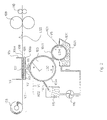
In a first implementation of a DEP device according to this
invention, said means for bringing toner particles to the surface
(103a) comprise in a container (1011) a dispenser (1041) for non-magnetic
mono component developer (1021) as shown in figure 2.
In a preferred embodiment of said first implementation of a
device according to this invention it further comprises means (116)
incorporating a pumping system for recycling said removed non-used
toner particles in said container (1011) for repeated use.
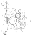
In a second implementation, which is the preferred one and is
shown in figure 3, of a DEP device according to this invention, said
means for bringing charged non-magnetic toner particles to said
toner bearing surface comprises in a container (101) a two-component
developer (102) with magnetic carrier particles (102b) and non-magnetic
toner particles (102a) and a magnetic brush (104) with a
sleeve (104b) arranged around a magnetic core (104a). Said sleeve
is connected to a DC voltage source (V5) so as to apply an
electrical potential difference between said sleeve and said toner
bearing surface connected to a DC voltage source (V1). This
potential difference makes the toner particles jump from said sleeve
to said surface (103a) of said toner conveyer(103).
In said second implementation of a DEP device according to this
invention the non-used toner particles can simply be recycled by
recycling means (116, 121) with pumping systems to said container
(101).
It is preferred in this second implementation that the recycling
means further comprises mixing means (117) for mixing the removed
toner particles with fresh toner particles contained in a container
(119) which may be coupled to the mixing means (117) and recycled in
to said container (101) with a magnetic brush (104). It is even
more beneficial that the removed toner particles are mixed not only
with fresh toner particles but also with fresh carrier particles
from a container (118) that can be coupled to said mixing means
(117). In this case the removed non-used toner particles are
recycled to said magnetic brush as part of a two-component
developer.
In a further preferred embodiment of said second implementation,
the device comprises further means (120) for bringing (used)
developer from the container (101) to the mixing means (117). In
this mixing means, the removed non-used toner particles are not only
mixed with fresh carrier particles and/or fresh toner particles but
also with (used) developer. Also in this case the non-used toner
particles are recycled to said magnetic brush as part of a two-component
developer.
In an other embodiment said means (115) and collecting the non-used
toner particles can be equipped for mixing said toner particles
with fresh carrier particles, fresh toner particles and/or used
developer so that the special mixing means (117) can be omitted.
A non limitative example of a device for implementing a DEP
method according to this invention using non-magnetic mono-component
developer is shown in fig 2. It comprises :
In figure 3, a DEP device according to the second implementation
of a device according to this invention is shown wherein the charged
toner particles on the surface of the CTC are brought there by a
magnetic brush from a two-component developer. Such device
comprises : (i) a means for bringing non magnetic charged toner
particles to the surface (103a) of a charged toner conveyer,
comprising a container (101) for two component developer (102), with
non-magnetic toner particles (102a) and magnetic carrier particles
(102b), a magnetic brush (104), with a magnetic core (104a) and a
non-magnetic sleeve (104b). Said sleeve is equipped with a means
(not shown in the figure) for rotating said sleeve, in the direction
of arrow C so that the surface of the sleeve has a linear speed LSM.
Said sleeve is coupled to a DC-voltage source V5 and an AC-voltage
source AC1 for jumping charged toner particles upon the surface
(103a) of said charged toner conveyer (103) from said two component
developer. The charged toner conveyer (103) is equipped with a
means (not shown in the figure) for rotating said it, in the
direction of arrow B, which is opposite to the direction of rotation
of the sleeve of the magnetic brush, so that the toner bearing
surface (103a) of it has a linear speed LSC. The CTC is rotated so
that the charged toner particles on its surface are brought in the
development zone (113), the magnetic brush (104) is located upstream
of the development zone.
The mixing means (117) can be provided with a system for
measuring the ratio toner particles/carrier particles present in
said mixing means and the measuring system can be coupled to means
for selectively opening and closing the inlets of the container for
fresh toner(119), the container of fresh carrier (118) and the inlet
(120) for bringing (used) developer to the mixing means.
It is clear that the mixing means (117) shown in figure 3 to be
coupled to containers for fresh toner and fresh carrier (118,119)
and to means (120) for bringing developer to the mixing means, can
be omitted totally form the device so that the recovered non-used
toner particles are directly as such recycled to the container
(101). A device wherein the mixing means is only coupled to a
container for fresh toner, or only to a container for fresh carrier
or only to means (120) for bringing developer to the mixing means is
also within the scope of the present invention. Also devices
wherein the mixing means are coupled to only two of a container for
fresh toner, a container for fresh carrier or means (120) for
bringing developer to the mixing means is also within the scope of
the present invention.
The means (104, 1041) for bringing charged non-magnetic toner
particles to the surface (103a) of the CTC can be equipped for
applying a mono layer of said toner particles on the surface of the
CTC or for applying multiple layers of said toner particles on top
of each other. In the latter case it can be beneficial to install
one or more doctor blades near the CTC between said means (104,
1041) for bringing charged non-magnetic toner particles to the
surface (103a) of the CTC and said development zone, (i.e. downstream
of the means for bringing toner particles to the CTC and upstream of
the development zone), for regulating the thickness of said multiple
layers of toner particles.
The location and/or form of the shield electrode (106b) and the
control electrode (106a) can, in other embodiments of a device for a
DEP method using toner particles according to the present invention,
be different from the location shown in fig. 2 or fig 3..
Although in fig. 2 and 3 an embodiment of a device for a DEP
method using two electrodes (106a and 106b) on printhead 106 is
shown, it is possible to implement a DEP method, using toner
particles according to the present invention using devices with
different constructions of the printhead (106). It is, e.g.
possible to implement a DEP method with a device having a printhead
comprising only one electrode structure as well as with a device
having a printhead comprising more than two electrode structures.
The apertures in these printhead structures can have a constant
diameter, or can have a broader entrance or exit diameter.
The back electrode (105) of this DEP device can also be made to
co-operate with the printhead structure, said back electrode being
constructed from different styli or wires that are galvanically
isolated and connected to a voltage source as disclosed in e.g.
US-A-4,568,955 and US-A-4,733,256. The back electrode, co-operating
with the printhead structure, can also comprise one or more flexible
PCB's (Printed Circuit Board).
Between said printhead structure (106) and the charged toner
conveyer (103) as well as between the control electrode around the
apertures (107) and the back electrode (105) behind the toner
receiving member (109) as well as on the single electrode surface or
between the plural electrode surfaces of said printhead structure
(106) different electrical fields are applied. In the specific
embodiment of a device, useful for a DEP method, using a printing
device with a geometry according to the present invention, shown in
fig 2. voltage V1 is applied to the sleeve of the charged toner
conveyer 103, voltage V2 to the shield electrode 106b, voltages V30
up to V3n for the control electrode (106a). The value of V3 is
selected, according to the modulation of the image forming signals,
between the values V30 and V3n, on a time basis or grey-level basis.
Voltage V4 is applied to the back electrode behind the toner
receiving member. In other embodiments of the present invention
multiple voltages V20 to V2n and/or V40 to V4n can be used. Voltage
V5 is applied to the surface of the sleeve of the magnetic brush.
In a DEP device according to the present invention an additional
AC-source can beneficially be connected to the sleeve of said
magnetic brush.
The magnetic brush 104 preferentially used in a DEP device
according to the present invention is of the type with stationary
core and rotating sleeve.
In a DEP device, according to a preferred embodiment of the
present invention, any type of known carrier particles and toner
particles can successfully be used. It is however preferred to use
"soft" magnetic carrier particles. "Soft" magnetic carrier
particles useful in a DEP device according to a preferred embodiment
of the present invention are soft ferrite carrier particles. Such
soft ferrite particles exhibit only a small amount of remanent
behaviour, characterised in coercivity values ranging from about 4
kA/m up to 20 kA/m (50 up to 250 Oe). Further very useful soft
magnetic carrier particles, for use in a DEP device according to a
preferred embodiment of the present invention, are composite carrier
particles, comprising a resin binder and a mixture of two magnetites
having a different particle size as described in EP-B 289 663. The
particle size of both magnetites will vary between 0.05 and 3 µm.
The carrier particles have preferably an average volume diameter
(dv50) between 10 and 300 µm, preferably between 20 and 100 µm.
More detailed descriptions of carrier particles, as mentioned above,
can be found in EP-A-675 417.
It is preferred to use in a DEP device according to the present
invention, toner particles with an absolute average charge over mass
ratio (|q/m|) corresponding to 5 µC/g ≤ |q/m| ≤ 15 µC/g , preferably
to 8 µC/g ≤ |q/m| ≤ 11 µC/g . The charge to mass ratio of the toner
particles is measured by mixing the toner particles with carrier
particles, and after 15 min of charging the q/m-ratio is measured
with a device such as the Toshiba TB-200 blow-off tester. In this
disclosure the charge to mass ratio is taken as the absolute value,
as a DEP device according to this invention can function either with
negatively charged toner particles or with positively charged toner
particles depending on the polarity of the potential difference
between V1 and V4. Preferably the toner particles used in a device
according to the present invention have an average volume diameter
(dv50) between 1 and 20 µm, more preferably between 3 and 15 µm.
More detailed descriptions of toner particles, as mentioned above,
can be found in EP A 675 417 that is incorporated herein by
reference.
A DEP device making use of the above mentioned marking toner
particles can be addressed in a way that enables it to give black
and white. It can thus be operated in a "binary way", useful for
black and white text and graphics and useful for classical bi-level
half-toning to render continuous tone images.
A DEP device according to the present invention is especially
suited for rendering an image with a plurality of grey levels. Grey
level printing can be controlled by either an amplitude modulation
of the voltage V3 applied on the control electrode 106a or by a time
modulation of V3. By changing the duty cycle of the time modulation
at a specific frequency, it is possible to print accurately fine
differences in grey levels. It is also possible to control the grey
level printing by a combination of an amplitude modulation and a
time modulation of the voltage V3, applied on the control electrode.
The combination of a high spatial resolution and of the multiple
grey level capabilities typical for DEP, opens the way for
multilevel half-toning techniques, such as e.g. described in
EP-A-634 862 with title "Screening method for a rendering device
having restricted density resolution". This enables the DEP device,
according to the present invention, to render high quality images.
Throughout the printing examples, the same developer, comprising
toner and carrier particles was used.
A macroscopic "soft" ferrite carrier consisting of a MgZn-ferrite
with average particle size 50 µm, a magnetisation at
saturation of 36 Tm3/kg (29 emu/g) was provided with a 1 µm thick
acrylic coating. The material showed virtually no remanence.
The toner used for the experiment had the following
composition : 97 parts of a co-polyester resin of fumaric acid and
bispropoxylated bisphenol A, having an acid value of 18 and volume
resistivity of 5.1 x 10¹⁶ ohm.cm was melt-blended for 30 minutes at
110° C in a laboratory kneader with 3 parts of Cu-phthalocyanine
pigment (Colour Index PB 15:3). A resistivity decreasing substance -
having the following formula : (CH3)3N+C16H33 Br- was added in a
quantity of 0.5 % with respect to the binder, as described in
WO-A-94/027192.
After cooling, the solidified mass was pulverised and milled
using an ALPINE Fliessbettgegenstrahlmühle type 100AFG (trade name)
and further classified using an ALPINE multiplex zig-zag classifier
type 100MZR (trade name). The average particle size was measured by
Coulter Counter model Multisizer (trade name), was found to be 6.3
µm by number and 8.2 µm by volume. In order to improve the
flowability of the toner mass, the toner particles were mixed with
0.5 % of hydrophobic colloidal silica particles (BET-value 130
m2/g).
An electrostatographic developer was prepared by mixing said
mixture of toner particles and colloidal silica in a 5 or 10 % ratio
(wt/wt) with carrier particles. The triboelectric charging of the
toner-carrier mixture was performed by mixing said mixture in a
standard tumbling set-up for 10 min. The developer mixture was run
in the magnetic brush for 5 minutes, after which the toner was
sampled and the tribo-electric properties were measured using the
Toshiba TB-200 blow-off device, resulting in a q/m-ratio of -14
µC/g.
A printhead structure (106) was made from a polyimide film of 50
µm thickness, double sided coated with a 5 µm thick copper film. The
printhead structure (106) had two rows of printing apertures. On the
back side of the printhead structure, facing the image receiving
member, a rectangular shaped control electrode (106a) was arranged
around each aperture. Each of said control electrodes was connected
over 2 MΩ resistors to a HV 507 (trade name) high voltage switching
IC, commercially available through Supertex, USA, that was powered
from a high voltage power amplifier. The printing apertures were
rectangular shaped with dimensions of 360 by 120 µm. The dimension
of the central part of the rectangular shaped copper control
electrodes was 500 by 260 µm. The apertures were spaced so to
obtain a resolution of 33 dots/cm (85 dpi). On the front side of
the printhead structure, facing the charged toner conveyer roller, a
common shield electrode (106b) was arranged around the aperture zone
leaving a free polyimide zone of 1620 µm. Said printhead structure
was fabricated in the following way. First of all the control and
shield electrode pattern was etched by conventional copper etching
techniques. The apertures were made by a step and repeat focused
excimer laser making use of the control electrode patterns as
focusing aid. After excimer burning the printhead structure was
cleaned by a short isotropic plasma etching cleaning. Finally a
thin coating of PLASTIK70, commercially available from Kontakt
Chemie, was applied over the control electrode side of said
printhead structure.
The CTC was a cylinder with a sleeve made of aluminium, coated
with TEFLON (trade name of Du Pont, Wilmington, USA) with a surface
roughness of 2.2 µm (Ra-value) and a diameter of 30 mm. The charged
toner conveyer (103) was connected to a DC power supply of 0V.
Charged toner particles were propelled to this conveyer from a
stationary core (104a)/rotating sleeve (104b) type magnetic brush
(104) comprising two mixing rods and one metering roller. One rod
was used to transport the developer through the unit, the other one
to mix toner with developer.
The magnetic brush 104 was constituted of the so called magnetic
roller, which in this case contained inside the roller assembly a
stationary magnetic core (104a), having three magnetic poles with an
open position (no magnetic poles present) to enable used developer
to fall off from the magnetic roller (open position was one quarter
of the perimeter and located at the position opposite to said CTC
(103).
The sleeve (104b) of said magnetic brush had a diameter of 20 mm and was made of stainless steel roughened with a fine grain to assist in transport (Ra=3 µm) and showed an external magnetic field strength in the zone between said magnetic brush and said CTC of 0.045 T, measured at the outer surface of the sleeve of the magnetic brush. The magnetic brush was connected to an AC power supply (AC1) with a square wave oscillating field between 500-3750 V peak to peak at a frequency of 3.0 kHz with -50 to -200 V DC-offset. The voltages of the AC-field and the DC offset (V5) were varied for the various printing examples (see table 1)
The sleeve (104b) of said magnetic brush had a diameter of 20 mm and was made of stainless steel roughened with a fine grain to assist in transport (Ra=3 µm) and showed an external magnetic field strength in the zone between said magnetic brush and said CTC of 0.045 T, measured at the outer surface of the sleeve of the magnetic brush. The magnetic brush was connected to an AC power supply (AC1) with a square wave oscillating field between 500-3750 V peak to peak at a frequency of 3.0 kHz with -50 to -200 V DC-offset. The voltages of the AC-field and the DC offset (V5) were varied for the various printing examples (see table 1)
A scraper blade was used to force developer to leave the
magnetic roller. On the other side a doctoring blade was used to
meter a small amount of developer onto the surface of said magnetic
brush. The sleeve was rotating at a linear surface speed (LSM) four
times higher than the linear surface speed (LSC) of said CTC roller,
and in a direction opposite to the rotation direction of said CTC-roller.
The reference surface of said CTC was placed at a distance between 550-800 µm from the reference surface of said magnetic brush. This distance was varied for the various printing examples (see table 1)
The reference surface of said CTC was placed at a distance between 550-800 µm from the reference surface of said magnetic brush. This distance was varied for the various printing examples (see table 1)
The printhead structure, mounted in a PVC-frame, was bent with
frictional contact over the surface of the roller of the charged
toner conveyer roller. A 50 µm (this is distance d) thick
polyurethane coating was used as self-regulating spacer means (110).
A back electrode was present behind the paper whereon the
printing proceeded, the distance between the back electrode (105)
and the back side of the printhead structure (dB) was set to 1000 µm
and the paper travelled a linear speed (LSM) of 200 cm/min. The
back electrode was connected to a high voltage power supply,
applying a voltage V4 of + 1000 V to the back electrode.
The shield electrode 106b was grounded V2 = 0 V. To the
individual control electrodes an (image-wise) voltage V3 between 0 V
and +280 V was applied.
A printout made on paper with a DEP device and developer
described above, was judged for homogeneity of the image density
after a long printing run.
The results are given in table 1. In this table the data on cloudiness are summarised according to the following ranking :
The results are given in table 1. In this table the data on cloudiness are summarised according to the following ranking :
In these experiments the charged toner conveyer roller was fed
from a single magnetic brush, wherein the distance between said
magnetic brush and said charged toner conveyer roller was modified,
the DC and AC-potential applied towards the sleeve of said magnetic
brush was modified, and in which the toner concentration of the
developer used was modified. The CTC was not cleaned downstream of
the development zone. The parameters of the printing engine are
summarised in table 1 and the printing results in table 2.
In this printing example a scraper blade was placed downstream
of the development zone to remove all unused toner from the charged
toner conveyer roller. Said toner was removed by means of air
suction. The amount of consumed toner was calculated and the
developer in said magnetic brush was "compensated" for this removed
amount of toner by fresh toner. No recycling of the removed non-used
toner particles took place. The parameters of the printing
engine are summarised in table 1 and the printing results in table
2.
In this printing example a scraper blade was used to remove all
unused toner from the charged toner conveyer roller. Said toner was
removed by pumping used developer through the tube in which said
toner was pushed by said scraper blade. The amount of consumed
toner was calculated and the developer in said magnetic brush was
"compensated" for this removed amount of toner by mixing the removed
non-used toner particles with part of the developer and then added
to the container of said magnetic brush holding said developer
material. In this example, the removed non-used toner particles
were recycled. The parameters of the printing engine are summarised
in table 1 and the printing results in table 2.
Experiment 11 was repeated except for the cleaning of the CTC
downstream of the development zone : a rotating roller with foamed
polymers was used in stead of said scraper blade of experiment 11.
The parameters of the printing engine are summarised in table 1
and the printing results in table 2.
Experiment 11 was repeated except for the cleaning of the CTC
downstream of the development zone : a pulling magnetic brush was
used in stead of said scraper blade of experiment 11. The pulling
magnetic brush was connected to a "suction" field. The non-used
toner particles were not recycled. The parameters of the printing
engine are summarised in table 1 and the printing results in table
2.
| Parameters of the printing engine. | ||||||||
| # | TC in % | X in µm | V1 in V | V4 in V | V5 in V | AC1 in V | Clean | Recycle |
| PE1 | 5 | 650 | 0 | 1000 | - 200 | 0 | no | no |
| PE2 | 5 | 650 | 0 | 1000 | - 50 | 0 | no | no |
| PE3 | 5 | 650 | 0 | 1000 | - 100 | 500 | no | no |
| PE4 | 5 | 650 | 0 | 1000 | - 100 | 2000 | no | no |
| PE5 | 5 | 650 | 0 | 1000 | - 100 | 3750 | no | no |
| PE6 | 5 | 800 | 0 | 1000 | - 100 | 500 | no | no |
| PE7 | 5 | 800 | 0 | 1000 | - 100 | 3000 | no | no |
| PE8 | 10 | 800 | 0 | 1000 | - 100 | 500 | no | no |
| PE9 | 10 | 800 | 0 | 1000 | - 100 | 3000 | no | no |
| PE10 | 5 | 650 | 0 | 1000 | - 100 | 1750 | sb | no |
| PE11 | 5 | 650 | 0 | 1000 | - 100 | 1750 | sb | yes |
| PE12 | 5 | 650 | 0 | 1000 | - 100 | 1750 | fr | yes |
| PE13 | 5 | 650 | 0 | 1000 | - 100 | 1750 | pb | no |
| Results of the printing | |||||||||
| # | m1 in g/m2 | m2 in g/m2 | m10 in g/m2 | m60 in g/m2 | q1 in µC/g | q2 in µC/g | q10 in µC/g | q60 in µC/g | QC after 60 min printing |
| PE1 | 9.1 | 17.3 | 21.6 | na | 12.5 | 12.5 | 15.1 | na | 2 |
| PE2 | 3.4 | 5.9 | 8.4 | na | 11.5 | 12.9 | 15.2 | na | 2 |
| PE3 | 7.2 | 12.5 | 14.1 | na | 12.6 | 12.8 | 16.1 | na | 2 |
| PE4 | 10.7 | 11.8 | 11.5 | na | 18.9 | 21.8 | 24.7 | na | 2 |
| PE5 | 2.3 | 4.5 | 8.0 | na | 14.1 | 16.1 | 20.3 | na | 1 |
| PE6 | 4.5 | 8.6 | 13.1 | 11.1 | 11.2 | 11.3 | 14.1 | 21.8 | 3 |
| PE7 | 5.7 | 11.2 | 14.0 | na | 11.4 | 11.2 | 14.5 | na | 3 |
| PE8 | 8.0 | 13.3 | 15.9 | 13.0 | 8.2 | 8.2 | 12.2 | 18.4 | 3 |
| PE9 | 2.0 | 4.3 | 8.7 | 8.0 | 7.1 | 9.1 | 10.6 | 10.5 | 3 |
| PE10 | 9.0 | 8.9 | 9.1 | 9.0 | 13.5 | 13.5 | 13.6 | 13.6 | 5 |
| PE11 | 8.9 | 9.2 | 9.1 | 9.0 | 13.6 | 13.5 | 13.5 | 13.6 | 5 |
| PE12 | 8.9 | 8.9 | 9.1 | 9.1 | 13.5 | 13.5 | 13.7 | 13.6 | 5 |
| PE13 | 8.9 | 8.9 | 8.1 | 7.6 | 13.5 | 13.5 | 13.9 | 16.5 | 3 |
It is clear from the examples above that only in the printing
experiments wherein the CTC is cleaned with a kind of mechanical
means (scraper blade, foamed roller) a stable load of toner
particles with a stable charge is maintained on the CTC even after
30 minutes of printing (PE10 to PE12). It is clear that the non-used
toner particles can be recycled without deteriorating the
printing quality (compare PE10 to PE 11 and PE 12).
Although a configuration wherein the cleaning proceeds with a
pulling magnetic brush (PE13) is acceptable for medium size run
lengths it is clear from table 2 that after 30 minutes of printing
the stability of the system both in terms of load of toner particles
and in terms of charge of the toner particles is deteriorated.
It must be clear for those skilled in the art that many other
implementations of cleaning and recovery systems can be provided
without departing from the spirit of the present invention.
Claims (14)
- A method for Direct Electrostatic Printing (DEP) is provided comprising the steps of :bringing charged toner particles from a means for delivering non magnetic toner particles to a toner bearing surface of a conveyer for charged toner,applying an electrical potential difference between said toner bearing surface and an image receiving member, for creating a flow of charged toner particles from said surface bearing charged toner particles to an image receiving member,placing a printhead structure having printing apertures and control electrodes in said flow, forming a development zone under said printing apertures for image wise depositing toner particles, from said flow of charged toner particles, on said image receiving membermoving said conveyer for charged toner particles to pass the toner bearing surface repeatedly through said development zone, in a direction so as to have said magnetic brush upstream of the development zone andremoving and collecting, downstream from said development zone, non-used toner particles from said toner bearing surface.
- A method according to claim 1, wherein said means for delivering toner particles comprises a dispenser for non-magnetic mono-component developer.
- A method according to claim 1 or 2, wherein said method further comprises the step of recycling said non-used toner particles in said-means for delivering toner particles.
- A method according to claim 1, wherein said means for delivering toner particles comprises a magnetic brush assembly (104) carrying non-magnetic toner particles (102a) and magnetic carrier particles (102b).
- A method according to claim 4, wherein said method further comprises the step of recycling said non-used toner particles in said means for delivering toner particles.
- A method according to claim 5, wherein said method further comprises the step of mixing said non-used toner particles with fresh toner particles.
- A device for direct electrostatic printing comprising :a means (104, 1041) with a container (101, 1011) for bringing charged non-magnetic toner particles to a toner bearing surface (103a) of a conveyer for charged toner (103),one or more voltage sources (V1, V4) for applying an electrical potential difference between said toner bearing surface and an image receiving member (109), for creating a flow (111) of charged toner particles from said surface bearing charged toner particles to said image receiving member,a printhead structure (106) having printing apertures (107) and control electrodes (106a) placed in said flow, forming a development zone (113) under said printing apertures for image wise depositing toner particles, from said flow of charged toner particles, on said image receiving membera means for moving said conveyer for charged toner particles, in a direction of arrow B, to pass said toner bearing surface repeatedly through said development zone so as to have said means for bringing charged toner particles on said surface upstream of the development zone anda means for removing (114) and collecting (115), downstream from said development zone, non-used toner particles from said toner bearing surface.
- A device according to claim 7, wherein said means for bringing toner particles to the surface (103a) contains a dispensing roller (1041) for non-magnetic mono component developer (1021).
- A device according to claim 7, wherein said means for bringing toner particles to the surface (103a) contains a magnetic brush assembly (104) containing magnetic carrier particles (102b) and non-magnetic toner particles (102a).
- A device according to any of claims 7 to 9, further comprising means (116) for recycling said non-used toner particles in said for bringing charged non-magnetic toner particles to said toner bearing surface.
- A device according to claim 9, further comprising mixing means (117) for mixing the non-used toner particles with fresh toner particles
- A device according to claim 9, wherein said collecting means contains mixing means (117) for mixing the non-used toner particles with fresh toner particles.
- A method according to any of claim 7 to 12, wherein said cleaning means (114) is a scraping blade.
- A method according to any of claim 7 to 12, wherein said cleaning means (114) is a foamed polymer roller.
Priority Applications (1)
| Application Number | Priority Date | Filing Date | Title |
|---|---|---|---|
| EP98202607A EP0978769A1 (en) | 1998-08-03 | 1998-08-03 | A method of printing in a device for direct electrostatic printing comprising a toner delivery means that comprises a charged toner conveying roll, a magnetic brush and a cleaning unit |
Applications Claiming Priority (1)
| Application Number | Priority Date | Filing Date | Title |
|---|---|---|---|
| EP98202607A EP0978769A1 (en) | 1998-08-03 | 1998-08-03 | A method of printing in a device for direct electrostatic printing comprising a toner delivery means that comprises a charged toner conveying roll, a magnetic brush and a cleaning unit |
Publications (1)
| Publication Number | Publication Date |
|---|---|
| EP0978769A1 true EP0978769A1 (en) | 2000-02-09 |
Family
ID=8234004
Family Applications (1)
| Application Number | Title | Priority Date | Filing Date |
|---|---|---|---|
| EP98202607A Withdrawn EP0978769A1 (en) | 1998-08-03 | 1998-08-03 | A method of printing in a device for direct electrostatic printing comprising a toner delivery means that comprises a charged toner conveying roll, a magnetic brush and a cleaning unit |
Country Status (1)
| Country | Link |
|---|---|
| EP (1) | EP0978769A1 (en) |
Cited By (1)
| Publication number | Priority date | Publication date | Assignee | Title |
|---|---|---|---|---|
| EP2003941A2 (en) | 2007-06-14 | 2008-12-17 | manroland AG | Printed functional components |
Citations (7)
| Publication number | Priority date | Publication date | Assignee | Title |
|---|---|---|---|---|
| JPS59232370A (en) * | 1983-06-15 | 1984-12-27 | Toshiba Corp | Developing device |
| US5040004A (en) * | 1989-12-18 | 1991-08-13 | Xerox Corporation | Belt donor for direct electrostatic printing |
| US5247333A (en) * | 1991-05-21 | 1993-09-21 | Fuji Xerox Co., Ltd. | One-component developing apparatus |
| JPH07121030A (en) * | 1993-10-28 | 1995-05-12 | Brother Ind Ltd | Image recorder |
| US5479195A (en) * | 1993-11-04 | 1995-12-26 | Brother Kogyo Kabushiki Kaisha | Image forming apparatus and method |
| EP0709748A2 (en) * | 1994-10-31 | 1996-05-01 | Sharp Kabushiki Kaisha | Developing device |
| DE19745561A1 (en) * | 1996-10-16 | 1998-04-23 | Array Printers Ab | Electrostatic printer, copier |
-
1998
- 1998-08-03 EP EP98202607A patent/EP0978769A1/en not_active Withdrawn
Patent Citations (7)
| Publication number | Priority date | Publication date | Assignee | Title |
|---|---|---|---|---|
| JPS59232370A (en) * | 1983-06-15 | 1984-12-27 | Toshiba Corp | Developing device |
| US5040004A (en) * | 1989-12-18 | 1991-08-13 | Xerox Corporation | Belt donor for direct electrostatic printing |
| US5247333A (en) * | 1991-05-21 | 1993-09-21 | Fuji Xerox Co., Ltd. | One-component developing apparatus |
| JPH07121030A (en) * | 1993-10-28 | 1995-05-12 | Brother Ind Ltd | Image recorder |
| US5479195A (en) * | 1993-11-04 | 1995-12-26 | Brother Kogyo Kabushiki Kaisha | Image forming apparatus and method |
| EP0709748A2 (en) * | 1994-10-31 | 1996-05-01 | Sharp Kabushiki Kaisha | Developing device |
| DE19745561A1 (en) * | 1996-10-16 | 1998-04-23 | Array Printers Ab | Electrostatic printer, copier |
Non-Patent Citations (2)
| Title |
|---|
| PATENT ABSTRACTS OF JAPAN vol. 009, no. 113 (P - 356) 17 May 1985 (1985-05-17) * |
| PATENT ABSTRACTS OF JAPAN vol. 095, no. 008 29 September 1995 (1995-09-29) * |
Cited By (3)
| Publication number | Priority date | Publication date | Assignee | Title |
|---|---|---|---|---|
| EP2003941A2 (en) | 2007-06-14 | 2008-12-17 | manroland AG | Printed functional components |
| EP2003940A2 (en) | 2007-06-14 | 2008-12-17 | manroland AG | Printed functional components |
| DE102007027473A1 (en) | 2007-06-14 | 2008-12-18 | Manroland Ag | Technically produced functional components |
Similar Documents
| Publication | Publication Date | Title |
|---|---|---|
| US5708464A (en) | Device for direct electrostatic printing (DEP) with "previous correction" | |
| EP0675417B1 (en) | A method and device for direct electrostatic printing (DEP) | |
| JP3237818B2 (en) | Printing head structure and DEP device | |
| US5774158A (en) | Device for direct electrostatic printing (DEP) comprising rows of smaller and larger sized apparatus | |
| EP0740224B1 (en) | A device for DEP (direct electrostatic printing) | |
| EP0812696B1 (en) | A printhead structure with specific shield electrode | |
| EP0978769A1 (en) | A method of printing in a device for direct electrostatic printing comprising a toner delivery means that comprises a charged toner conveying roll, a magnetic brush and a cleaning unit | |
| EP0736822B1 (en) | A device for direct electrostatic printing (DEP) | |
| US5984443A (en) | Direct electrostatic printing device which uses a gas stream to provide a cloud of toner particles | |
| US6102523A (en) | Printer for large format printing using a direct electrostatic printing (DEP) engine | |
| EP0763785B1 (en) | A DEP (Direct Electrostatic Printing) device using gas stream to provide a toner cloud | |
| US6246424B1 (en) | Device for large format printing comprising a single central conditioning unit for controlling and monitoring the condition of the developer | |
| US6012802A (en) | Device for direct electrostatic print (DEP) comprising individual control print and control back electrodes | |
| US5900893A (en) | Direct electrostatic printing device wherein the speeds of a magnetic brush and a receiving substrate are related to each other | |
| EP0710897B1 (en) | A device for direct electrostatic printing (DEP) comprising an individual shield and control electrode per aperture | |
| EP0984336B1 (en) | A device for large format printing comprising a single central conditioning unit for controlling and monitoring the condition of the developer | |
| EP0849645A1 (en) | A printer for large format printing using a direct electrostatic printing (DEP) engine | |
| US5738009A (en) | Method for direct electrostatic printing (DEP) | |
| EP0731394B1 (en) | A device for direct electrostatic printing (DEP) comprising a magnetic brush and printhead structure with special geometry | |
| EP0753413B1 (en) | A printhead structure for use in a DEP device | |
| US6059398A (en) | Printhead structure having electrodes not extending to the edge of printing apertures | |
| JP3159940B2 (en) | Printhead structure with special shield electrode | |
| EP0911706A1 (en) | A device for direct electrostatic printing with a conventional printhead structure and AC-coupling to the control electrode | |
| EP1003083B1 (en) | A device for large format printing comprising a single central conditioning unit for controlling and monitoring the condition of the developer | |
| EP1093033A1 (en) | A method for direct electrostatic printing using toner particles with adapted charging properties |
Legal Events
| Date | Code | Title | Description |
|---|---|---|---|
| PUAI | Public reference made under article 153(3) epc to a published international application that has entered the european phase |
Free format text: ORIGINAL CODE: 0009012 |
|
| AK | Designated contracting states |
Kind code of ref document: A1 Designated state(s): AT BE CH CY DE DK ES FI FR GB GR IE IT LI LU MC NL PT SE |
|
| AX | Request for extension of the european patent |
Free format text: AL;LT;LV;MK;RO;SI |
|
| AKX | Designation fees paid | ||
| STAA | Information on the status of an ep patent application or granted ep patent |
Free format text: STATUS: THE APPLICATION IS DEEMED TO BE WITHDRAWN |
|
| 18D | Application deemed to be withdrawn |
Effective date: 20000810 |