EP0978487A2 - Sealed, nozzle-mix burners for silica deposition - Google Patents
Sealed, nozzle-mix burners for silica deposition Download PDFInfo
- Publication number
- EP0978487A2 EP0978487A2 EP99113418A EP99113418A EP0978487A2 EP 0978487 A2 EP0978487 A2 EP 0978487A2 EP 99113418 A EP99113418 A EP 99113418A EP 99113418 A EP99113418 A EP 99113418A EP 0978487 A2 EP0978487 A2 EP 0978487A2
- Authority
- EP
- European Patent Office
- Prior art keywords
- burner
- tube
- entrance port
- passage
- face
- Prior art date
- Legal status (The legal status is an assumption and is not a legal conclusion. Google has not performed a legal analysis and makes no representation as to the accuracy of the status listed.)
- Withdrawn
Links
Images



Classifications
-
- F—MECHANICAL ENGINEERING; LIGHTING; HEATING; WEAPONS; BLASTING
- F23—COMBUSTION APPARATUS; COMBUSTION PROCESSES
- F23L—SUPPLYING AIR OR NON-COMBUSTIBLE LIQUIDS OR GASES TO COMBUSTION APPARATUS IN GENERAL ; VALVES OR DAMPERS SPECIALLY ADAPTED FOR CONTROLLING AIR SUPPLY OR DRAUGHT IN COMBUSTION APPARATUS; INDUCING DRAUGHT IN COMBUSTION APPARATUS; TOPS FOR CHIMNEYS OR VENTILATING SHAFTS; TERMINALS FOR FLUES
- F23L7/00—Supplying non-combustible liquids or gases, other than air, to the fire, e.g. oxygen, steam
-
- C—CHEMISTRY; METALLURGY
- C03—GLASS; MINERAL OR SLAG WOOL
- C03B—MANUFACTURE, SHAPING, OR SUPPLEMENTARY PROCESSES
- C03B19/00—Other methods of shaping glass
- C03B19/14—Other methods of shaping glass by gas- or vapour- phase reaction processes
- C03B19/1407—Deposition reactors therefor
-
- C—CHEMISTRY; METALLURGY
- C03—GLASS; MINERAL OR SLAG WOOL
- C03B—MANUFACTURE, SHAPING, OR SUPPLEMENTARY PROCESSES
- C03B19/00—Other methods of shaping glass
- C03B19/14—Other methods of shaping glass by gas- or vapour- phase reaction processes
- C03B19/1415—Reactant delivery systems
- C03B19/1423—Reactant deposition burners
-
- F—MECHANICAL ENGINEERING; LIGHTING; HEATING; WEAPONS; BLASTING
- F23—COMBUSTION APPARATUS; COMBUSTION PROCESSES
- F23D—BURNERS
- F23D14/00—Burners for combustion of a gas, e.g. of a gas stored under pressure as a liquid
- F23D14/20—Non-premix gas burners, i.e. in which gaseous fuel is mixed with combustion air on arrival at the combustion zone
- F23D14/22—Non-premix gas burners, i.e. in which gaseous fuel is mixed with combustion air on arrival at the combustion zone with separate air and gas feed ducts, e.g. with ducts running parallel or crossing each other
-
- F—MECHANICAL ENGINEERING; LIGHTING; HEATING; WEAPONS; BLASTING
- F23—COMBUSTION APPARATUS; COMBUSTION PROCESSES
- F23D—BURNERS
- F23D14/00—Burners for combustion of a gas, e.g. of a gas stored under pressure as a liquid
- F23D14/32—Burners for combustion of a gas, e.g. of a gas stored under pressure as a liquid using a mixture of gaseous fuel and pure oxygen or oxygen-enriched air
-
- F—MECHANICAL ENGINEERING; LIGHTING; HEATING; WEAPONS; BLASTING
- F23—COMBUSTION APPARATUS; COMBUSTION PROCESSES
- F23D—BURNERS
- F23D14/00—Burners for combustion of a gas, e.g. of a gas stored under pressure as a liquid
- F23D14/46—Details
- F23D14/48—Nozzles
- F23D14/52—Nozzles for torches; for blow-pipes
-
- C—CHEMISTRY; METALLURGY
- C03—GLASS; MINERAL OR SLAG WOOL
- C03B—MANUFACTURE, SHAPING, OR SUPPLEMENTARY PROCESSES
- C03B2207/00—Glass deposition burners
- C03B2207/04—Multi-nested ports
- C03B2207/06—Concentric circular ports
-
- C—CHEMISTRY; METALLURGY
- C03—GLASS; MINERAL OR SLAG WOOL
- C03B—MANUFACTURE, SHAPING, OR SUPPLEMENTARY PROCESSES
- C03B2207/00—Glass deposition burners
- C03B2207/04—Multi-nested ports
- C03B2207/08—Recessed or protruding ports
-
- C—CHEMISTRY; METALLURGY
- C03—GLASS; MINERAL OR SLAG WOOL
- C03B—MANUFACTURE, SHAPING, OR SUPPLEMENTARY PROCESSES
- C03B2207/00—Glass deposition burners
- C03B2207/04—Multi-nested ports
- C03B2207/12—Nozzle or orifice plates
-
- C—CHEMISTRY; METALLURGY
- C03—GLASS; MINERAL OR SLAG WOOL
- C03B—MANUFACTURE, SHAPING, OR SUPPLEMENTARY PROCESSES
- C03B2207/00—Glass deposition burners
- C03B2207/04—Multi-nested ports
- C03B2207/14—Tapered or flared nozzles or ports angled to central burner axis
-
- C—CHEMISTRY; METALLURGY
- C03—GLASS; MINERAL OR SLAG WOOL
- C03B—MANUFACTURE, SHAPING, OR SUPPLEMENTARY PROCESSES
- C03B2207/00—Glass deposition burners
- C03B2207/20—Specific substances in specified ports, e.g. all gas flows specified
-
- C—CHEMISTRY; METALLURGY
- C03—GLASS; MINERAL OR SLAG WOOL
- C03B—MANUFACTURE, SHAPING, OR SUPPLEMENTARY PROCESSES
- C03B2207/00—Glass deposition burners
- C03B2207/20—Specific substances in specified ports, e.g. all gas flows specified
- C03B2207/22—Inert gas details
-
- C—CHEMISTRY; METALLURGY
- C03—GLASS; MINERAL OR SLAG WOOL
- C03B—MANUFACTURE, SHAPING, OR SUPPLEMENTARY PROCESSES
- C03B2207/00—Glass deposition burners
- C03B2207/20—Specific substances in specified ports, e.g. all gas flows specified
- C03B2207/26—Multiple ports for glass precursor
-
- C—CHEMISTRY; METALLURGY
- C03—GLASS; MINERAL OR SLAG WOOL
- C03B—MANUFACTURE, SHAPING, OR SUPPLEMENTARY PROCESSES
- C03B2207/00—Glass deposition burners
- C03B2207/30—For glass precursor of non-standard type, e.g. solid SiH3F
- C03B2207/32—Non-halide
-
- C—CHEMISTRY; METALLURGY
- C03—GLASS; MINERAL OR SLAG WOOL
- C03B—MANUFACTURE, SHAPING, OR SUPPLEMENTARY PROCESSES
- C03B2207/00—Glass deposition burners
- C03B2207/30—For glass precursor of non-standard type, e.g. solid SiH3F
- C03B2207/34—Liquid, e.g. mist or aerosol
-
- C—CHEMISTRY; METALLURGY
- C03—GLASS; MINERAL OR SLAG WOOL
- C03B—MANUFACTURE, SHAPING, OR SUPPLEMENTARY PROCESSES
- C03B2207/00—Glass deposition burners
- C03B2207/36—Fuel or oxidant details, e.g. flow rate, flow rate ratio, fuel additives
-
- C—CHEMISTRY; METALLURGY
- C03—GLASS; MINERAL OR SLAG WOOL
- C03B—MANUFACTURE, SHAPING, OR SUPPLEMENTARY PROCESSES
- C03B2207/00—Glass deposition burners
- C03B2207/42—Assembly details; Material or dimensions of burner; Manifolds or supports
-
- C—CHEMISTRY; METALLURGY
- C03—GLASS; MINERAL OR SLAG WOOL
- C03B—MANUFACTURE, SHAPING, OR SUPPLEMENTARY PROCESSES
- C03B2207/00—Glass deposition burners
- C03B2207/46—Comprising performance enhancing means, e.g. electrostatic charge or built-in heater
-
- C—CHEMISTRY; METALLURGY
- C03—GLASS; MINERAL OR SLAG WOOL
- C03B—MANUFACTURE, SHAPING, OR SUPPLEMENTARY PROCESSES
- C03B2207/00—Glass deposition burners
- C03B2207/50—Multiple burner arrangements
- C03B2207/52—Linear array of like burners
-
- F—MECHANICAL ENGINEERING; LIGHTING; HEATING; WEAPONS; BLASTING
- F23—COMBUSTION APPARATUS; COMBUSTION PROCESSES
- F23C—METHODS OR APPARATUS FOR COMBUSTION USING FLUID FUEL OR SOLID FUEL SUSPENDED IN A CARRIER GAS OR AIR
- F23C2900/00—Special features of, or arrangements for combustion apparatus using fluid fuels or solid fuels suspended in air; Combustion processes therefor
- F23C2900/06043—Burner staging, i.e. radially stratified flame core burners
-
- F—MECHANICAL ENGINEERING; LIGHTING; HEATING; WEAPONS; BLASTING
- F23—COMBUSTION APPARATUS; COMBUSTION PROCESSES
- F23D—BURNERS
- F23D2900/00—Special features of, or arrangements for burners using fluid fuels or solid fuels suspended in a carrier gas
- F23D2900/00018—Means for protecting parts of the burner, e.g. ceramic lining outside of the flame tube
-
- F—MECHANICAL ENGINEERING; LIGHTING; HEATING; WEAPONS; BLASTING
- F23—COMBUSTION APPARATUS; COMBUSTION PROCESSES
- F23L—SUPPLYING AIR OR NON-COMBUSTIBLE LIQUIDS OR GASES TO COMBUSTION APPARATUS IN GENERAL ; VALVES OR DAMPERS SPECIALLY ADAPTED FOR CONTROLLING AIR SUPPLY OR DRAUGHT IN COMBUSTION APPARATUS; INDUCING DRAUGHT IN COMBUSTION APPARATUS; TOPS FOR CHIMNEYS OR VENTILATING SHAFTS; TERMINALS FOR FLUES
- F23L2900/00—Special arrangements for supplying or treating air or oxidant for combustion; Injecting inert gas, water or steam into the combustion chamber
- F23L2900/07002—Injecting inert gas, other than steam or evaporated water, into the combustion chambers
Definitions
- This invention relates to fused silica glass and, in particular, to burners for producing silica soot from which such glass can be made.
- silica glass includes glass which is pure or may contain one or more dopants, as does the term "silica soot”.
- An effective method for making fused silica glass comprises the steps of: (1) generating silica soot particles using soot producing burners, and (2) collecting and consolidating the particles on a rotating substrate to form a glass "boule".
- Such boules can have diameters on the order of five feet (1.5 meters) and thicknesses on the order of 5-10 inches (13-25 cm).
- the process is typically carried out in a furnace which has a rotatable base, an outer ring wall, and a crown which carries the soot producing burners.
- Figure 1 shows the front face 8 of a soot producing burner 7 which has been used in the past to produce fused silica boules.
- This burner has five zones or regions 10, 12, 14, 16, and 18 through which gases of different compositions pass to (1) supply the raw material(s) from which the soot particles are produced, and (2) generate a flame of suitable size and temperature to (a) convert the raw material(s) into soot particles and (b) generate sufficient heat to consolidate the particles as they are collected at the surface of the boule.
- region 10 is referred to as the "fume tube” and carries, for example, a mixture of nitrogen gas and a vaporized silicon-containing compound
- regions 12 and 18 are known as the inner and outer shields, respectively, and carry oxygen
- regions 14 and 16 are referred to as the "premix rings” and carry a mixture of fuel (e.g., methane) and oxygen.
- the diameter of outer shield 18 is typically about 1.1 inches (2.8 cm), while the overall dimensions of front face 8 are typically about 3.4 inches by 3.4 inches (8.5 cm by 8.5 cm).
- the vaporized silicon-containing compound supplied to fume tube 10 was silicon tetrachloride or a mixture of silicon tetrachloride and chlorides of other materials, e.g., titanium tetrachloride, when a doped glass was desired.
- silicon tetrachloride has now been replaced with halide-free, silicon-containing compounds, of which octamethylcyclotetrasiloxane (OMCTS) is a particularly preferred example since in addition to providing silicon, it is also provides energy for the burner's flame.
- organometallic compounds have been substituted for chloride compounds in the production of doped glasses.
- FIG 2 shows the manner in which burners of the type shown in Figure 1 have been positioned relative to the furnace's crown 20.
- burner 7 is spaced from the outer face 22 of the crown (the "cold" face of the crown) by gap 24.
- This gap which in practice is about a quarter inch in height, allows air to be inspirated into the furnace so as to cool burner hole 26 and prevent soot buildup on the walls of the hole. The entrained air also ensures that complete combustion of the fuel occurs in burner flame 38.
- Figure 2 shows the connection of feed lines 28, 30, and 32 to the burner, as well as lines 34 and 36 which carry cooling water to and from the burner.
- the burners of the present invention address and provide solutions to each of these problems.
- PCT Patent Publication No. WO 97/22553 published on June 26, 1997, discloses soot producing burners which can be used with halide-free, silicon-containing compounds such as octamethylcyclotetrasiloxane (OMCTS).
- OCTS octamethylcyclotetrasiloxane
- the halide-free, silicon-containing compound is preferably provided to the burner as a liquid, atomized in the burner by an integral atomizer, and then directly converted into soot particles by the burner's flame. See also pending U.S. applications numbers 08/767,653 and 08/903,501, filed December 17, 1996 and July 30, 1997, respectively, the contents of both of which are incorporated herein by reference.
- Brown et al., U.S. Patent No. 5,092,760 discloses an oxygen/fuel burner which atomizes liquid fuel by means of an integral atomizer.
- Brown et al., U.S. Patents Nos. 5,405,082 and 5,560,758, disclose oxygen/fuel burners for use in glass conditioning. These burners employ a tube-in-tube construction and, during use, are sealed to the wall of a glass distribution channel.
- Brown et al., U.S. Patent No. 4,986,748 discloses a further construction for an oxygen/fuel burner.
- the burners of these various Brown et al. patents are concerned with heat production, not with the production of silica soot. Among other things, such heat producing burners do not have to be concerned with soot build-up on the burner face or with the adverse effects of the burner's internal operating temperature on the heat-sensitive raw material(s) used to produce silica soot.
- the invention achieves these and other objects by providing soot producing burners and furnaces employing such burners which have some or all of the following properties:
- the invention provides improved burners which are economical to build, use, and service, and which allow for more efficient and controlled production of fused silica boules.
- burner 40 includes manifold portion 42 and nozzle portion 44.
- the nozzle portion forms a seal with crown 20 at chamfered surface 46.
- Manifold portion 42 has six entrance ports for receiving processing gases, fuel, and the raw material(s) which forms the soot.
- the burner includes six tubes which by means of the tube-in-tube construction form six passages for carrying the gases, fuels, and raw materials (collectively, the "source materials").
- Table 1 sets forth the correspondence between the source materials, the entrance ports, the passages, and the tubes.
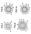
- Figures 6-9 illustrate the use of a restriction zone 48 formed by flats 50 on the outer surface of tube 301 to apply shear to the liquid raw material flowing in passage 202.
- the spaces 52 between the outer surface of tube 301 and the inner surface of tube 302 at the restriction zone can, for example, have a maximum thickness of 0.005 inches (0.13 millimeters). All other dimensions being held constant, the use of more or less flats will respectively decrease or increase this maximum thickness. Using routine experimentation, persons skilled in the art can readily determine a suitable number of flats for any particular application of the invention.
- the cross-sectional area of passage 202 decreases as the liquid raw material approaches the restriction zone and then increases after the raw material has passed through the restriction zone.
- these decreases and increases in cross-sectional area can be achieved by providing the outer surface of tube 301 and the inner surface of tube 302 with tapers which begin at different locations and have different taper angles.
- the outer surface of tube 301 can begin tapering closer to the face of the burner and can have a taper angle of, for example, 5° while the inner surface of tube 302 can begin tapering farther from the burner face and can have a taper angle of, for example, 31 ⁇ 2°. In this way, these surfaces converge before the restriction zone and diverge after that zone.
- Other taper configurations can, of course, be used in the practice of the invention.
- the outer surface of tube 301 can have a taper angle of 4° when used with the embodiment of Figure 11.
- Figures 6-9 also illustrate (1) the merger of passage 202 with passage 201 downstream of the restriction zone and (2) the use of a restriction rod 54 to reduce the cross-sectional area of passage 202 after the merger and to also reduce the cross-sectional area of passage 201 prior to the merger.
- the use of this restriction rod in combination with the merger of passage 201 with passage 202 further enhance the atomization of the liquid raw material.
- the merger and the restriction rod enhance atomization through the application of relatively high pressure O 2 to the droplets of liquid raw material created at the restriction zone.
- restriction zone 48 Other configurations for restriction zone 48 include the following:
- Figures 4 and 4A show the nozzle portion of burner 40 downstream of restriction zone 48.
- tube 305 includes flats 56.
- the spaces 58 between the outer surface of tube 305 and the inner surface of tube 306 formed by these flats can, for example, have a maximum thickness of 0.01 inches (0.25 millimeters).
- flats 50 the use of more or less flats will respectively decrease or increase this maximum thickness. Using routine experimentation, persons skilled in the art will readily be able to determine a suitable number of flats for any particular application of the invention.
- Figures 10 and 10A show a variation of Figures 4 and 4A wherein passage 203 has been omitted. Corresponding changes are made to the manifold portion of the burner (not shown).
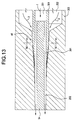
- Figure 11 shows a further variation in which passage 202 extends beyond the face of the burner and passages 203, 204, 205, and 206 are angled towards passage 202 to fully develop (streamline) the gas flows exiting the burner face and thus improve the burner's flame characteristics.
- the amount of extension of passage 202 beyond the face of the burner will depend upon the particular application of the invention. In general, this extension will be about 0.25 inches (6.4 millimeters).
- passage 204 narrows as it approaches the face of the burner, while passage 205 widens.
- the inclination of the inner and outer surfaces of tubes 302, 303, 304, 305, and 306 relative to the burners axis is set forth in Table 2. The values given in this table are for natural gas as the fuel and OMCTS as the silicon-containing raw material. Different angles may be required for other fuels and source materials. Based on the disclosure herein, the particular angles and dimensions to be used for any particular application of the invention can be readily determined by those skilled in the art using routine experimentation.
- Figure 11 also illustrates the use of drilled apertures 403, 404, 405, and 406 to form portions of passages 203, 204, 205, and 206, respectively. These apertures facilitate the manufacture of the various tubes making up the burner through a combination of drilling the apertures and machining the tube surfaces to achieve the desired part configurations.
- the atomization apparatus of Figures 6-9 or the variations thereof discussed above can be incorporated in this burner in the same manner as it is incorporated in the burners of Figures 4 and 10.
- the burner of Figure 11, as well as those of Figures 4 and 10 can be used without an internal atomizer.
- the soot producing material e.g., OMCTS
- entrance port 102 in vaporized form, optionally mixed with, for example, nitrogen, from which it passes to the face of the burner through passage 202. Entrance port 101 and tube 301 are then not included as part of the burner.
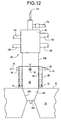
- Figure 12 illustrates the use of an external air cooled jacket 60 for providing additional cooling to the burner in cases where the internal flow of gases through the burner is not sufficient to keep the burner's internal operating temperature at a desired value.
- Air cooled jacket 60 has an air inlet 62 which is connected to an internal plenum 66. It also has a series of air outlets 64 which are connected to external plenum 68.
- the cross-sectional area of the external plenum is preferably greater than the cross-sectional area of the internal plenum to accommodate the increase in volume of the cooling air as it is heated by contact with the outer surface of tube 306.
- Figure 12 also illustrates the mating of the burner of Figure 11 with the furnace's crown. Since the front end of the nozzle of this burner is already slanted, a chamfer is not required to provide a suitable surface for sealing engagement with burner hole 26. It should be noted that the burner of Figures 11 and 12, as well as those of Figures 4 and 10, are self-aligning with respect to burner hole 26. This feature provides more efficient furnace assembly compared to the prior art burner of Figures 1 and 2 which had to be aligned with the burner hole. Also, impingement of the burner flame on the walls of the burner hole is less likely with the burners of the invention than with the previously used burners.
- the burner of Figures 11 and 12 was tested using the flow rates and source material temperatures set forth in Table 3.
- Room temperature air was supplied to air cooled jacket 60 at a rate of 15 cubic feet per hour.
- a thermocouple was mounted to the face of tube 306 and recorded temperatures in the range of 350-400°C during operation of the burner. These temperatures are well within the operating range of a burner constructed of, for example, stainless steel and are suitable for use with OMCTS as the liquid raw material.
- Tube 302 With tube 302 extending beyond the face of the burner and with O 2 flowing in passage 203, essentially no build up of soot on the face of the burner was observed. Soot build up, however, was observed when either of these preferred features of the burner was omitted.
- a glass boule was prepared using vaporized OMCTS in a nitrogen carrier and the apparatus of Figures 11 and 12.
- the flow rates used are shown in Table 4. The burner was found to work successfully in all respects and to produce high quality glass.
- manifold 42 can be constructed of aluminum
- tube 306 of Figures 4 and 10 can be made of a refractory material, e.g., alumina
- tube 306 of Figures 11 and 12 can be made of stainless steel
- all other tubes can likewise be made of stainless steel.
- Other materials can, of course, be used in the practice of the invention.
- Source Material Flow Arrow Entrance Port Passage Passage Cross-Sectional Area in inches 2 (cm 2 ) Tubes Which Define Passage O 2 1 101 201 0.0034 (0.02) Inner surface of 301.
- Liquid raw material e.g., OMCTS 2 102 202 0.0034 (0.02) Inner surface of 302 and outer surface of 301.
- O 2 or an inert gas e.g., argon 3 103 203 0.015 (0.09) Inner surface of 303 and outer surface of 302.
Landscapes
- Engineering & Computer Science (AREA)
- Chemical & Material Sciences (AREA)
- Combustion & Propulsion (AREA)
- Mechanical Engineering (AREA)
- General Engineering & Computer Science (AREA)
- Chemical Kinetics & Catalysis (AREA)
- Manufacturing & Machinery (AREA)
- Materials Engineering (AREA)
- Organic Chemistry (AREA)
- Glass Melting And Manufacturing (AREA)
- Gas Burners (AREA)
Abstract
Description
- 1-6
- flow arrows
- 7
- previously used soot producing burner
- 8
- front face of previously used soot producing burner
- 10
- fume tube of previously used soot producing burner
- 12
- inner shield of previously used soot producing burner
- 14
- premix ring of previously used soot producing burner
- 16
- premix ring of previously used soot producing burner
- 18
- outer shield of previously used soot producing burner
- 20
- furnace crown
- 22
- outer face of furnace crown
- 24
- gap between previously used soot producing burner and furnace crown
- 26
- burner hole
- 28
- feed line
- 30
- feed line
- 32
- feed line
- 34
- line for cooling water
- 36
- line for cooling water
- 38
- burner flame
- 40
- burner of present invention
- 42
- manifold portion of
burner 40 - 44
- nozzle portion of
burner 40 - 46
- chamfered surface of
nozzle 44 - 48
- restriction zone
- 50
- flats
- 52
- spaces formed by
flats 50 - 54
- restriction rod
- 56
- flats
- 58
- spaces formed by
flats 56 - 60
- air cooled jacket
- 62
- air inlet of air cooled jacket
- 64
- air outlet of air cooled jacket
- 66
- internal plenum of air cooled jacket
- 68
- external plenum of air cooled jacket
- 70
- air flow arrow
- 72
- annular ring for atomization
- 74
- burner axis
- 101-106
- entrance ports
- 201-206
- passages
- 301-306
- tubes
- 403-406
- drilled apertures
| Source Material | Flow Arrow | Entrance Port | Passage | Passage Cross-Sectional Area in inches2 (cm2) | Tubes Which Define Passage |
| O2 | 1 | 101 | 201 | 0.0034 (0.02) | Inner surface of 301. |
| Liquid raw material, e.g., | 2 | 102 | 202 | 0.0034 (0.02) | Inner surface of 302 and outer surface of 301. |
| O2 or an inert gas, e.g., | 3 | 103 | 203 | 0.015 (0.09) | Inner surface of 303 and outer surface of 302. |
| O2 | 4 | 104 | 204 | 0.037 (0.24) | Inner surface of 304 and outer surface of 303. |
| Fuel, e.g., natural gas, methane, or | 5 | 105 | 205 | 0.05 (0.32) | Inner surface of 305 and outer surface of 304. |
| | 6 | 106 | 206 | 0.098 (0.63) | Inner surface of 306 and outer surface of 305. |
| Surface | Inclination Angle α |
| Inner surface of | 3.5° to the right of the burner face; 0° to the left of the burner face. |
| Outer surface of | 4° |
| Inner surface of | 4° |
| Outer surface of | 6.5° |
| Inner surface of | 8° |
| Outer surface of | 10° |
| Inner surface of | 8° |
| Outer surface of | 10° |
| Inner surface of | 10° |
| Outer surface of | 15° |
| Source Material | Passage | Source Material Flow Rate | Source Material Temperature (°C) |
| | 201 | 7 slpm | 15 |
| OMCTS | 202 | 6.5 g/min | 15 |
| O2 | 203 | 10 slpm | 15 |
| O2 | 204 | 20 slpm | 15 |
| | 205 | 20 slpm | 15 |
| O2 | 206 | 20 slpm | 15 |
| Source Material | Passage | Source Material Flow Rate | Source Material Temperature (°C) |
| | 202 | 6.5 g/min | 175 |
| | 202 | 5 slpm | 175 |
| | 203 | 10 slpm | 15 |
| O2 | 204 | 20 slpm | 15 |
| | 205 | 20 slpm | 15 |
| O2 | 206 | 20 slpm | 15 |
Claims (34)
- A burner for producing silica soot from a plurality of source materials which comprise a silicon-containing source material, fuel, oxygen, and optionally an inert gas, said burner having a burner face and a tube-in-tube construction which defines a plurality of passages for carrying flows of source materials to the burner face, said burner comprising:(a) a first entrance port which provides one of oxygen and the silicon-containing source material to the burner, said first entrance port being connected to a first passage defined by a first tube, said first passage extending from the first entrance port towards the burner face;(b) a second entrance port which provides the other of oxygen and the silicon-containing source material to the burner, said second entrance port being connected to a second passage defined by the first tube and by a second tube, said second passage extending from the second entrance port towards the burner face;(c) a third entrance port which provides oxygen or an inert gas to the burner, said third entrance port being connected to a third passage defined by the second tube and by a third tube, said third passage extending from the third entrance port towards the burner face;(d) a fourth entrance port which provides oxygen to the burner, said fourth entrance port being connected to a fourth passage defined by the third tube and by a fourth tube, said fourth passage extending from the fourth entrance port towards the burner face;(e) a fifth entrance port which provides fuel to the burner, said fifth entrance port being connected to a fifth passage defined by the fourth tube and by a fifth tube, said fifth passage extending from the fifth entrance port towards the burner face; and(f) a sixth entrance port which provides oxygen to the burner, said sixth entrance port being connected to a sixth passage defined by the fifth tube and by a sixth tube, said sixth passage extending from the sixth entrance port towards the burner face;
wherein the sixth tube surrounds the fifth tube which surrounds the fourth tube which surrounds the third tube which surrounds the second tube which surrounds the first tube. - The burner of Claim 1 wherein at least one of the tubes comprises flats for reducing a transverse cross-sectional area of a passage.
- The burner of Claim 1 wherein the second entrance port provides the silicon-containing source material to the burner, the silicon-containing source material is a liquid, and the second passage comprises a restriction zone for atomizing the liquid, said restriction zone being located between the second entrance port and the burner face.
- The burner of Claim 3 wherein the restriction zone comprises flats formed on at least one of the first and second tubes.
- The burner of Claim 3 wherein the restriction zone comprises an annular ring of reduced cross-sectional area formed by a taper on at least one of the first and second tubes.
- The burner of Claim 3 wherein the second passage has a transverse cross-sectional area which increases both in a direction from the restriction zone towards the second entrance port and in a direction from the restriction zone towards the burner face.
- The burner of Claim 6 wherein at least one of the first and second tubes comprises a taper which produces said increases in transverse cross-sectional area.
- The burner of Claim 3 wherein the first and second passages merge at a location between the restriction zone and the burner face.
- The burner of Claim 8 further comprising a restriction rod which reduces at least one transverse cross-sectional area of the first passage and at least one transverse cross-sectional area of the merged first and second passages.
- The burner of Claim 1 wherein the second tube extends beyond the face of the burner.
- The burner of Claim 10 wherein the flows of source materials carried by the third, fourth, fifth, and sixth passages are angled towards the second tube at the burner face.
- The burner of Claim 1 wherein the sixth tube has an outer surface which comprises an angled portion for sealing engagement with a burner hole formed in a crown of a furnace.
- The burner of Claim 1 wherein the sixth tube has an outer surface and the burner further comprises an air cooled jacket which surrounds at least a portion of said outer surface.
- The burner of Claim 1 wherein the fifth passage is isolated from the fourth and sixth passages so that fuel and oxygen do not mix within the burner.
- A method for making a fused silica glass comprising:(a) providing a furnace crown having at least one burner hole;(b) providing a burner according to Claim 1;(c) sealing the burner to the at least one burner hole;(d) providing one of oxygen and a silicone-containing source material to the burner's first entrance port;(e) providing the other of oxygen and a silicon-containing source material to the burner's second entrance port;(f) providing oxygen or an inert gas to the burner's third entrance port;(g) providing oxygen to the burner's fourth entrance port;(h) providing fuel to the burner's fifth entrance port; and(i) providing oxygen to the burner's sixth entrance port.
- The method of Claim 15 wherein oxygen is provided to the burner's third entrance port in step (f).
- A burner for producing silica soot from a plurality of source materials which comprise a silicon-containing source material in vapor form, fuel, oxygen, and optionally an inert gas, said burner having a burner face and a tube-in-tube construction which defines a plurality of passages for carrying flows of source materials to the burner face, said burner comprising:(a) a first entrance port which provides the silicon-containing source material to the burner, said first entrance port being connected to a first passage defined by the first tube, said first passage extending from the first entrance port towards the burner face;(b) a second entrance port which provides oxygen or an inert gas to the burner, said second entrance port being connected to a second passage defined by the first tube and by a second tube, said second passage extending from the second entrance port towards the burner face;(c) a third entrance port which provides oxygen to the burner, said third entrance port being connected to a third passage defined by the second tube and by a third tube, said third passage extending from the third entrance port towards the burner face;(d) a fourth entrance port which provides fuel to the burner, said fourth entrance port being connected to a fourth passage defined by the third tube and by a fourth tube, said fourth passage extending from the fourth entrance port towards the burner face; and(e) a fifth entrance port which provides oxygen to the burner, said fifth entrance port being connected to a fifth passage defined by the fourth tube and by a fifth tube, said fifth passage extending from the fifth entrance port towards the burner face;
wherein the fifth tube surrounds the fourth tube which surrounds the third tube which surrounds the second tube which surrounds the first tube. - The burner of Claim 17 wherein at least one of the tubes comprises flats for reducing a transverse cross-sectional area of a passage.
- The burner of Claim 17 wherein the first tube extends beyond the face of the burner.
- The burner of Claim 19 wherein the flows of source materials carried by the second, third, fourth, and fifth passages are angled towards the first tube at the burner face.
- The burner of Claim 17 wherein the fifth tube has an outer surface which comprises an angled portion for sealing engagement with a burner hole formed in a crown of a furnace.
- The burner of Claim 17 wherein the fifth tube has an outer surface and the burner further comprises an air cooled jacket which surrounds at least a portion of said outer surface.
- The burner of Claim 17 wherein the fourth passage is isolated from the third and fifth passages so that fuel and oxygen do not mix within the burner.
- A method of making a fused silica glass comprising:(a) providing a furnace crown having at least one burner hole;(b) providing a burner according to Claim 17;(c) sealing the burner to the at least one burner hole;(d) providing a silicon-containing source material in vapor form to the burner's first entrance port;(e) providing oxygen or an inert gas to the burner's second entrance port;(f) providing oxygen to the burner's third entrance port;(g) providing fuel to the burner's fourth entrance port; and(h) providing oxygen to the burner's fifth entrance port.
- A burner comprising a plurality of concentric tubes, said tubes defining a plurality of passages, at least one of said tubes comprising flats for reducing a cross-sectional area of a passage.
- A burner comprising a plurality of concentric tubes, said tubes defining a plurality of passages, at least one of said passages comprising a restriction zone for atomizing a liquid source material flowing in said passage.
- The burner of Claim 26 wherein the restriction zone comprises flats on at least one of the tubes which defines said at least one passage.
- The burner of Claim 26 wherein the restriction zone comprises an annulus of reduced cross-sectional area produced by a taper on at least one of the tubes which defines said at least one passage.
- The burner of Claim 26 wherein said passage has a transverse cross-sectional area which increases both in a direction upstream from the restriction zone and in a direction downstream from the restriction zone.
- The burner of Claim 29 wherein at least one of said tubes comprises a taper which produces said increases in transverse cross-sectional area.
- The burner of Claim 26 wherein said at least one passage merges with another passage downstream of said restriction zone to form a merged passage.
- The burner of Claim 31 further comprising a restriction rod which reduces at least one transverse cross-sectional area of said at least one passage and at least one transverse cross-sectional area of said merged passage.
- A burner for producing silica soot, said burner having a burner face and comprising a plurality of concentric tubes, said tubes defining a plurality of passages, wherein one of the tubes extends beyond the face of the burner and at least some of the remaining tubes are angled towards said one tube at the burner face.
- A furnace for produced fused silica comprising a crown and a plurality of soot producing burners wherein the soot producing burners are sealed to the crown.
Applications Claiming Priority (2)
| Application Number | Priority Date | Filing Date | Title |
|---|---|---|---|
| US9574198P | 1998-08-07 | 1998-08-07 | |
| US95741P | 1998-08-07 |
Publications (2)
| Publication Number | Publication Date |
|---|---|
| EP0978487A2 true EP0978487A2 (en) | 2000-02-09 |
| EP0978487A3 EP0978487A3 (en) | 2001-02-21 |
Family
ID=22253385
Family Applications (1)
| Application Number | Title | Priority Date | Filing Date |
|---|---|---|---|
| EP99113418A Withdrawn EP0978487A3 (en) | 1998-08-07 | 1999-07-12 | Sealed, nozzle-mix burners for silica deposition |
Country Status (3)
| Country | Link |
|---|---|
| US (1) | US6588230B1 (en) |
| EP (1) | EP0978487A3 (en) |
| JP (1) | JP2000063127A (en) |
Cited By (5)
| Publication number | Priority date | Publication date | Assignee | Title |
|---|---|---|---|---|
| WO2000060286A1 (en) | 1999-04-06 | 2000-10-12 | Shin-Etsu Chemical Co., Ltd. | Burner and combustion furnace for combustion and flame hydrolysis and combustion method |
| EP1067096A3 (en) * | 1999-07-07 | 2001-10-17 | Shin-Etsu Chemical Co., Ltd. | Quartz glass members for excimer laser, and their method of manufacture |
| WO2002049978A1 (en) * | 2000-12-21 | 2002-06-27 | Corning Incorporated | Refractories for fused silica production furnaces |
| WO2004056714A1 (en) * | 2002-12-20 | 2004-07-08 | Pirelli & C. S.P.A. | Burner for chemical vapour deposition of glass |
| EP1296899A4 (en) * | 2000-05-31 | 2004-11-17 | Corning Inc | Fused silica with constant induced absorption |
Families Citing this family (20)
| Publication number | Priority date | Publication date | Assignee | Title |
|---|---|---|---|---|
| US20020005051A1 (en) * | 2000-04-28 | 2002-01-17 | Brown John T. | Substantially dry, silica-containing soot, fused silica and optical fiber soot preforms, apparatus, methods and burners for manufacturing same |
| DE10043601A1 (en) * | 2000-09-01 | 2002-03-14 | Aixtron Ag | Device and method for depositing, in particular, crystalline layers on, in particular, crystalline substrates |
| US20040216494A1 (en) * | 2000-09-19 | 2004-11-04 | Shinichi Kurotani | Burner for combustion or flame hydrolysis, and combustion furnace and process |
| JP3750728B2 (en) * | 2000-12-05 | 2006-03-01 | 信越化学工業株式会社 | Method for producing fine silica |
| US20050120752A1 (en) * | 2001-04-11 | 2005-06-09 | Brown John T. | Substantially dry, silica-containing soot, fused silica and optical fiber soot preforms, apparatus, methods and burners for manufacturing same |
| DE10231037C1 (en) * | 2002-07-09 | 2003-10-16 | Heraeus Tenevo Ag | Making synthetic quartz glass blank by plasma-assisted deposition, for optical fiber manufacture, employs burner to focus flow towards plasma zone |
| EP1471038A3 (en) * | 2003-04-26 | 2005-11-23 | Schott Ag | Process for producing glass articles of doped silica glass |
| US20060162382A1 (en) * | 2004-12-30 | 2006-07-27 | Hrdina Kenneth E | Method and apparatus for producing oxide particles via flame |
| US20070158466A1 (en) * | 2005-12-29 | 2007-07-12 | Harmon Michael P | Nozzle assembly |
| JP4750867B2 (en) * | 2009-02-24 | 2011-08-17 | 信越化学工業株式会社 | Burner for manufacturing porous glass base material and method for manufacturing porous glass base material |
| GB2478307A (en) | 2010-03-02 | 2011-09-07 | Heraeus Quartz Uk Ltd | Manufacture of silica glass |
| JP5653681B2 (en) * | 2010-08-19 | 2015-01-14 | コバレントマテリアル徳山株式会社 | Synthetic silica glass manufacturing apparatus and synthetic silica glass manufacturing method |
| JP5381946B2 (en) * | 2010-09-21 | 2014-01-08 | 住友電気工業株式会社 | Manufacturing method of glass base material |
| CA2851739C (en) * | 2011-10-18 | 2019-06-11 | Shell Internationale Research Maatschappij B.V. | Production of synthesis gas |
| JP5935882B2 (en) * | 2012-12-28 | 2016-06-15 | 住友電気工業株式会社 | Method for producing glass particulate deposit and method for producing glass base material |
| JP2015093816A (en) * | 2013-11-13 | 2015-05-18 | 住友電気工業株式会社 | Manufacturing method for glass fine particle deposit and manufacturing method for glass preform |
| JP6086168B2 (en) * | 2016-04-01 | 2017-03-01 | 住友電気工業株式会社 | Method for producing glass particulate deposit and method for producing glass base material |
| US10745804B2 (en) * | 2017-01-31 | 2020-08-18 | Ofs Fitel, Llc | Parallel slit torch for making optical fiber preform |
| CN107056042B (en) * | 2017-04-17 | 2023-05-09 | 江苏亨通光导新材料有限公司 | Blowtorch of optical fiber preform |
| JP6756759B2 (en) * | 2018-03-22 | 2020-09-16 | 信越化学工業株式会社 | Optical fiber base material manufacturing equipment |
Family Cites Families (28)
| Publication number | Priority date | Publication date | Assignee | Title |
|---|---|---|---|---|
| US1759769A (en) * | 1924-05-20 | 1930-05-20 | Vuillaume Cyprien | Blowpipe |
| JPS5927728B2 (en) * | 1977-08-11 | 1984-07-07 | 日本電信電話株式会社 | Manufacturing method of sooty glass rod |
| JPS582171A (en) * | 1981-06-22 | 1983-01-07 | フジテック株式会社 | Controller for speed of elevator |
| JPS60228812A (en) * | 1984-04-27 | 1985-11-14 | Furukawa Electric Co Ltd:The | Glass burner and manufacture thereof |
| JPH0624987B2 (en) * | 1984-07-13 | 1994-04-06 | 旭硝子株式会社 | Burner for synthesizing porous quartz glass base material |
| JPH0667764B2 (en) * | 1985-05-27 | 1994-08-31 | 古河電気工業株式会社 | Burner for producing fine glass particles |
| JPS62187135A (en) * | 1986-02-12 | 1987-08-15 | Furukawa Electric Co Ltd:The | Torch for synthesizing fine glass particle |
| JPS63139030A (en) * | 1986-11-28 | 1988-06-10 | Sumitomo Electric Ind Ltd | Manufacturing method of optical fiber base material |
| JPH085687B2 (en) * | 1987-05-07 | 1996-01-24 | 旭硝子株式会社 | Method for producing porous quartz glass base material |
| JPH01257147A (en) * | 1988-04-05 | 1989-10-13 | Japan Metals & Chem Co Ltd | Multitube burner for production of synthetic quartz ingot |
| JPH0669898B2 (en) * | 1989-08-08 | 1994-09-07 | 矢崎総業株式会社 | Torch for synthesizing porous base material for optical fiber |
| AU643451B2 (en) * | 1989-08-28 | 1993-11-18 | Sumitomo Electric Industries, Ltd. | Method for producing porous glass preform for optical fiber |
| US4986748A (en) | 1989-12-15 | 1991-01-22 | Corning Incorporated | Wide range oxy-fuel burner and furnace operation |
| US5110335A (en) | 1990-06-25 | 1992-05-05 | At&T Bell Laboratories | Method of glass soot deposition using ultrasonic nozzle |
| US5092760A (en) | 1990-08-01 | 1992-03-03 | Maxon Corporation | Oxygen-fuel burner assembly and operation |
| US5152819A (en) | 1990-08-16 | 1992-10-06 | Corning Incorporated | Method of making fused silica |
| US5043002A (en) | 1990-08-16 | 1991-08-27 | Corning Incorporated | Method of making fused silica by decomposing siloxanes |
| JPH04228440A (en) * | 1990-12-27 | 1992-08-18 | Sumitomo Electric Ind Ltd | Glass body manufacturing method |
| JPH0517164A (en) * | 1991-07-02 | 1993-01-26 | Furukawa Electric Co Ltd:The | Method for synthesizing glass particles |
| US5154744A (en) | 1991-08-26 | 1992-10-13 | Corning Incorporated | Method of making titania-doped fused silica |
| US5699183A (en) * | 1993-02-10 | 1997-12-16 | Nikon Corporation | Silica glass member for UV-lithography, method for silica glass production, and method for silica glass member production |
| JP3120647B2 (en) * | 1993-12-27 | 2000-12-25 | 株式会社ニコン | Method for producing quartz glass and quartz glass produced thereby |
| JP3007510B2 (en) * | 1993-04-27 | 2000-02-07 | 信越化学工業株式会社 | Manufacturing method of synthetic quartz glass member |
| US5405082A (en) | 1993-07-06 | 1995-04-11 | Corning Incorporated | Oxy/fuel burner with low volume fuel stream projection |
| JP3520541B2 (en) * | 1993-12-27 | 2004-04-19 | 株式会社ニコン | Quartz glass burner, quartz glass produced using the same, method for producing quartz glass using quartz glass burner |
| JPH08157235A (en) * | 1994-11-30 | 1996-06-18 | Fujikura Ltd | Method and apparatus for manufacturing porous glass body |
| KR100473827B1 (en) * | 1995-12-19 | 2005-07-18 | 코닝 인코포레이티드 | Method and apparatus for forming fused silica by combustion of liquid reactants |
| DE19725955C1 (en) * | 1997-06-19 | 1999-01-21 | Heraeus Quarzglas | Quartz glass preform production for optical fibre manufacture |
-
1999
- 1999-07-12 EP EP99113418A patent/EP0978487A3/en not_active Withdrawn
- 1999-07-30 US US09/364,149 patent/US6588230B1/en not_active Expired - Fee Related
- 1999-08-09 JP JP11225726A patent/JP2000063127A/en not_active Withdrawn
Cited By (10)
| Publication number | Priority date | Publication date | Assignee | Title |
|---|---|---|---|---|
| WO2000060286A1 (en) | 1999-04-06 | 2000-10-12 | Shin-Etsu Chemical Co., Ltd. | Burner and combustion furnace for combustion and flame hydrolysis and combustion method |
| EP1087177A4 (en) * | 1999-04-06 | 2002-08-21 | Shinetsu Chemical Co | Burner and combustion furnace for combustion and flame hydrolysis and combustion method |
| EP1067096A3 (en) * | 1999-07-07 | 2001-10-17 | Shin-Etsu Chemical Co., Ltd. | Quartz glass members for excimer laser, and their method of manufacture |
| US6541405B1 (en) | 1999-07-07 | 2003-04-01 | Shin-Etsu Chemical Co., Ltd. | Synthetic quartz glass member for excimer laser and method of making |
| EP1296899A4 (en) * | 2000-05-31 | 2004-11-17 | Corning Inc | Fused silica with constant induced absorption |
| WO2002049978A1 (en) * | 2000-12-21 | 2002-06-27 | Corning Incorporated | Refractories for fused silica production furnaces |
| US6923021B2 (en) | 2000-12-21 | 2005-08-02 | Corning Incorporated | Method and apparatus for fused silica production |
| WO2004056714A1 (en) * | 2002-12-20 | 2004-07-08 | Pirelli & C. S.P.A. | Burner for chemical vapour deposition of glass |
| CN1694849B (en) * | 2002-12-20 | 2010-04-28 | 普里斯曼电缆及系统能源有限公司 | Burners for chemical vapor deposition of glass |
| US8567218B2 (en) | 2002-12-20 | 2013-10-29 | Prysmian Cavi E Sistemi Energia S.R.L. | Burner for chemical vapour deposition of glass |
Also Published As
| Publication number | Publication date |
|---|---|
| US6588230B1 (en) | 2003-07-08 |
| JP2000063127A (en) | 2000-02-29 |
| EP0978487A3 (en) | 2001-02-21 |
Similar Documents
| Publication | Publication Date | Title |
|---|---|---|
| US6588230B1 (en) | Sealed, nozzle-mix burners for silica deposition | |
| KR101129628B1 (en) | Burner for production of inorganic sphericalized particle | |
| US6068468A (en) | Refractory block for use in a burner assembly | |
| US5490775A (en) | Forward injection oxy-fuel burner | |
| US5984667A (en) | Combustion process and apparatus therefore containing separate injection of fuel and oxidant streams | |
| EP0340424B1 (en) | Oxygen jet burner and combustion method | |
| JP4260948B2 (en) | Burners and combustion methods and methods for their use | |
| US5823769A (en) | In-line method of burner firing and NOx emission control for glass melting | |
| US5092760A (en) | Oxygen-fuel burner assembly and operation | |
| KR100197470B1 (en) | Quartz glass blank manufacturing method and apparatus used therein | |
| EP0563793A2 (en) | Adjustable momentum self-cooled oxy/fuel burner for heating in high-temperature environments | |
| JPH0135246B2 (en) | ||
| EP1203754B1 (en) | Process and vertical furnace for producing glass beads | |
| RU2391298C2 (en) | Plasma burner for making synthetic silicon dioxide | |
| JP5074094B2 (en) | Burner for producing inorganic spheroidized particles | |
| EP1572593B1 (en) | Burner for chemical vapour deposition of glass | |
| US6672106B1 (en) | Method and apparatus for forming soot for the manufacture of glass | |
| US5603456A (en) | Liquid fuel burner | |
| US6751987B1 (en) | Burners for producing boules of fused silica glass | |
| EP4035767A1 (en) | Burner for manufacturing inorganic spheroidized particles, inorganic spheroidized particle manufacturing device, and method for manufacturing inorganic spheroidized particles | |
| EP1140715A1 (en) | Burners for producing boules of fused silica glass | |
| US6339940B1 (en) | Synthetic quartz glass manufacturing process | |
| JP2013019557A (en) | Tubular flame burner and method for processing glass | |
| US6735981B2 (en) | High heat capacity burners for producing fused silica boules | |
| AU759821B2 (en) | Method and apparatus for forming soot for the manufacture of glass |
Legal Events
| Date | Code | Title | Description |
|---|---|---|---|
| PUAI | Public reference made under article 153(3) epc to a published international application that has entered the european phase |
Free format text: ORIGINAL CODE: 0009012 |
|
| AK | Designated contracting states |
Kind code of ref document: A2 Designated state(s): DE FR GB |
|
| AX | Request for extension of the european patent |
Free format text: AL;LT;LV;MK;RO;SI |
|
| PUAL | Search report despatched |
Free format text: ORIGINAL CODE: 0009013 |
|
| AK | Designated contracting states |
Kind code of ref document: A3 Designated state(s): AT BE CH CY DE DK ES FI FR GB GR IE IT LI LU MC NL PT SE |
|
| AX | Request for extension of the european patent |
Free format text: AL;LT;LV;MK;RO;SI |
|
| 17P | Request for examination filed |
Effective date: 20010328 |
|
| AKX | Designation fees paid |
Free format text: DE FR GB |
|
| 17Q | First examination report despatched |
Effective date: 20030203 |
|
| GRAP | Despatch of communication of intention to grant a patent |
Free format text: ORIGINAL CODE: EPIDOSNIGR1 |
|
| RTI1 | Title (correction) |
Free format text: METHOD OF MAKING FUSED SILICA GLASS |
|
| STAA | Information on the status of an ep patent application or granted ep patent |
Free format text: STATUS: THE APPLICATION IS DEEMED TO BE WITHDRAWN |
|
| 18D | Application deemed to be withdrawn |
Effective date: 20061006 |